Table of Contents
Advertisement
Quick Links
Advertisement
Table of Contents

Related Manuals for Abtus ABT4650 RouteScan


Summary of Contents for Abtus ABT4650 RouteScan
- Page 1 ABT4650 RouteScan Instruction Manual 4650-1 Issue 04...
- Page 2 1.0 Index Index Item List Specification Getting Started Overview Assembly Bluetooth Connection Single Point Measurement Recording Data Software Features Settings View Results File Types Transferring Recorded Data Files to a PC Target Pole Maintenance Before Each Use Every 3 Months Annual Measurement Characteristics Point Co-ordinates...
-
Page 3: Specification
2.0 Item List 1. RouteScan 2. Control Unit 3. Carry Case 4. Instruction Manual 5. RouteScan Charger 6. Control Unit Charger 7. Optical Cleaning Kit 8. Target Pole (if purchased separately) 3.0 Specification On track(RouteScan) 9.5kg Weight (Control Unit) 0.2kg In Box 25kg On Track(RouteScan) -
Page 4: Getting Started
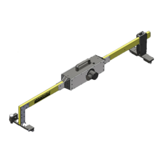
4.0 Getting Started Overview The RouteScan has been developed to provide quick, accurate structure clearance measurements relative to the Permanent Way. With the RouteScan in position on the track, the operator is able to control, from a position of safety, the measurement laser using the Control Unit via a Bluetooth connection. -
Page 5: Bluetooth Connection
Control Unit models may vary) – wait until the Windows operating system has fully loaded 2. Load the Abtus Gauge Interface software from the Start Menu (as shown in Figure 1) – the software launches directly to the ‘Connection’ screen... - Page 6 6. When the connection has been made, the ‘Options’ screen is displayed (Figure 3) The Abtus Gauge Interface software is common to all Abtus Bluetooth products and so it is possible to ‘Pair’ the Control Unit with a number of different gauges...
-
Page 7: Single Point Measurement
Figure 3 7. If the connection fails see Section 9.3 for help 8. Rotate the black lens cover to reveal the optical lens before attempting to take any readings (Figure 4) Figure 4 Single Point Measurement To make a single point measurement: 1. -
Page 8: Recording Data
ticking the ‘Absolute’ tick box • Tick the ‘Target Pole’ tick box to measure to a point using the target pole Figure 5 Note – it is not possible to send commands from the Control Unit when the Laser Housing is rotating. Ensure that the Laser Housing is stationary before clicking any buttons or closing a window. - Page 9 can be added by selecting ‘More’. Hide the keypad and select ‘Start Recording’ When ready, select ’Start’ to begin the scanning process. The Laser Housing unit will begin to rotate and after a short period measurement data will begin to appear on the display. The scan is automatically broken up into sections.
-
Page 10: Software Features
5.0 Software Features Settings Within the settings page (Figure 7) it is possible to create/edit any number of scan parameter sets. The parameters in each set define how a scan is performed: • Start Angle • End Angle • Increment (Resolution) •... -
Page 11: File Types
SD card) and insert it into the PC 2. Navigate to the above location on your PC using Windows Explorer and copy the Data Files as required Abtus Ltd can supply SD Card readers that connect to a USB port. 4650-1 Issue 04... - Page 12 Target Pole The target pole is an optional accessory for RouteScan. It allows the measurement of points that cannot be ‘seen’ directly by the laser, such as the gauge corner of the rail on an adjacent track. It is comprised of: •...
- Page 13 The Pointed Foot and Rounded Foot click into the bottom of the Target Pole and are interchangeable. When using the Target Pole on its own, it is advisable to use the Rounded Foot to minimise wear to the Pointed Foot (refer to Section 7.2). When using the Target Pole with the Rail Pole, the Pointed Foot must be fitted.
-
Page 14: Maintenance
An annual electrical insulation test should be carried out. The ABT4650 must be returned to Abtus Ltd annually for re-calibration to ensure measurements are within specification. The ABT4650 will also be tested for electrical insulation compliance at the same time. If using the Target Pole accessory, this should be re-calibrated at the same time. -
Page 15: Measurement Characteristics
8.0 Measurement Characteristics Point Co-ordinates Range 0.2-30m Accuracy ±3mm @ 4.0m ±6mm @ 8.0m Resolution Gauge Range -15/+25mm (on nominal) Accuracy ±0.5mm Resolution 0.1mm Super-Elevation Range ±200mm Accuracy ±1.2mm Resolution 0.1mm Super Elevation (SE) is measured across the running rails and is displayed as height differential between the high and low rail in millimetres - ive SE is the right rail lower than the left rail + ive SE is the right rail higher than the left rail... -
Page 16: Trouble Shooter
9.0 Trouble shooter Tips for Good Recording The ABT4650 is a very accurate piece of equipment – many of the parameters that it measures rely on extremely sensitive sensors. While every reasonable effort has been made to make it ‘railway proof’, users should treat it with extreme care.
Need help?
Do you have a question about the ABT4650 RouteScan and is the answer not in the manual?
Questions and answers