Table of Contents
Advertisement
Quick Links
Advertisement
Table of Contents

Related Manuals for Abtus ABT-7100


Summary of Contents for Abtus ABT-7100
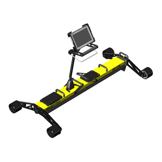
- Page 1 ABT-7100 Abtus Track Geometry Measurement Device Instruction Manual...
- Page 2 Index Index ............................2 Item List ............................3 Specification ..........................4 Getting Started ........................... 5 Overview ..........................5 Assembly ..........................6 Maintenance ..........................13 Every 3 Months ........................13 Annual ..........................13 Measurement Characteristics ....................13 Gauge ..........................13 Super-Elevation ........................13 Twist ...........................
- Page 3 2.0 Item List TGMD = R (Right Side – Sprung end) + L (Left Side – Fixed end) + H (Handle) (See assembly section of this manual) • (1) (Right Side) contains: Gauge Retraction Lever (A) • (2) (Left Side) contains: 2x Removable 12V Lithium Ion Batteries (B), On/Off Power Button (C) &...
-
Page 4: Specification
3.0 Specification - TGMD on Track 25 kg - Bag 1 & Bag 2 3 kg ea. (Total 6 kg) Weight - Panasonic Fz-G1 Tablet 1.1 kg - Chargers & Other 1 kg & 1 kg - TGMD in Bags 35 kg - TGMD on Track Length: 1610 mm to 1700 mm... -
Page 5: Getting Started
4.0 Getting Started Overview The Abtus ABT-7100 is a measuring device which records track geometry while being pushed by an operator at walking speed. The device can be assembled by one operator. Since the trolley weighs 25 kg, it should only be lifted in its entirety if the user feels feel fit to do so, otherwise the trolley should be disassembled and carried by two operators. - Page 6 Assembly • Place the wheel arm labelled ‘L’ and the fixed end of the track geometry trolley side by side as shown in Figure 1. Figure 1 Attaching wheel arm to trolley (Left side) • Push the locating pins at the end of the trolley body into the corresponding slots on the wheel arm.
- Page 7 • Position the locking lever towards the left as shown in Figure 3. Figure 3 - Initial Locking Position • Push the two halves together as shown in Figure 4 & Figure 5. Figure 4 - Joining of the Fixed & Rotating Halves Figure 5 - Two Halves Together ABT 7100 –...
- Page 8 • Lock the two halves together by pushing the locking lever towards the right until it firmly snaps into position. Figure 6 - Locked Position • Before attaching the handle, ensure that the locking levers are positioned towards the plunger on the back of the handle block as shown in Figure 7Figure 7. Handle Rotation Plunger...
- Page 9 • Attach the handle to the TGMD ensuring that the indication marks are aligned as shown in Figure 8. Figure 8 - Attaching the Handle Figure 9 - Handle Before Locked (levers towards green dot) ABT 7100 – Issue 02...
- Page 10 • To lock the handle into position, rotate the locking levers away from the indication mark (green dot) as shown in Figure 10. Figure 10 - Handle in its Locked Position • The TGMD comes with a tablet holder for the Panasonic FZ-G1 as shown in Figure 11, which is spring loaded for ease of insertion and removal.
- Page 11 • To attach the holder to the TGMD handle, simply insert the two 1” diameter rubber balls into the short double socket arm cups as shown in Figure 12Figure 12. Figure 12 - Short Double Socket Arm • The TGMD has been designed with the user in mind. The trolley has a rotating handle to prevent the user having to lift and rotate the trolley on track.
- Page 12 • The TGMD trolley has a retraction lever to allow the user on track to retract the gauge through switch and crossing. The trolley uses a spring to self-align in the running rails, the gauge is in its released position when the lever is towards the right as shown in Figure 14. Figure 14 - Fully Extended The gauge is in its retracted position when the lever is towards the left as shown in Figure 15.
-
Page 13: Maintenance
If the equipment becomes defective, or if it has an out of date calibration sticker, a warning notice should be placed on the device to prevent further use and should be returned to Abtus for repair, maintenance and re-calibration. -
Page 14: Transportation And Storage
The default sign convention is: Left rail up is positive Cant/SE. During geometry measurements the left and right side is determined by the direction of travel. The user is able to spin the handle around and whichever direction they are walking in, the left rail up is positive cant. -
Page 15: Software Introduction
Track Geometry faults. 8.2 Initial Setup No initial setup is required as Abtus will install the TGMD software and any necessary wireless drivers. If the Windows device does not connect to the TGMD, contact Abtus for support. - Page 16 The trolley is fitted with a dead man brake which can cause flat spots on the wheels if the brakes are engaged whilst pushing the trolley. Check all wheels for flats or grooves. If any are found, the trolley must be returned to Abtus as this can result in inaccuracies. •...
- Page 17 10.0 Step by Step Guide to Recording Geometry Measurements on Track Step 1 Setting New Geometry Profiles Open TGMD software on the windows tablet and click “Geometry Profiles” to set the tolerance parameters (Figure 17). Figure 17 Chaining Geometry Profile You can create a new profile by clicking on the “Create New Profile”, which will open the window shown...
- Page 18 Figure 19 Profile settings Figure 20 shows the newly Geometry Profile. Pressing the “Make profile active” button will make this profile the active profile used in the succeeding recordings. Figure 20 Activating the profile ABT 7100 – Issue 02...
- Page 19 STEP 2. Put the TGMD on the track The TGMD should be positioned on the track with the fixed side (marked L) on the left rail, facing the desired direction of travel. STEP 3. Connect the Windows device to the TGMD - Turn on the TGMD and the Windows device.
- Page 20 STEP 4: Start Geometry Recording Once the TGMD is in position press the “Set Zero Position” to reset the position reading to zero. Figure 22 Setting the zero position Press “Geometry Recording” to open the window shown in Figure 23. - Input the Operator name.
- Page 21 Figure 24 Geometry recording in progress Push the TGMD along the track and the red line of the screen which indicates the position of the TGMD will also move along the graph. The Gauge, SE and Twist are all measured and the instantaneous readings can be found above the graph along with the current position.
- Page 22 STEP 5: Start Geometry Recording Press “View a recording” to open the results screen which is shown in Figure 26. Figure 26 Viewing track gauge results with events This will show the Results screen. You can choose to plot Track gauge, Super elevation or Twist over 3 metres.
- Page 23 Figure 27 CSV Report 10.1 Tools - The Track gauge, Super elevation and their limits of the track can be shown. Figure 28 Track Gauge ABT 7100 – Issue 02...
- Page 24 Figure 29 Super Elevation (Cant) - The Twist can be shown along with whether it is within allowable limits (shown by dotted horizontal blue and red lines). Figure 30 Twist Over 3 Meters ABT 7100 – Issue 02...
-
Page 25: Troubleshooting
11.0 Troubleshooting Track Geometry Software not working Close the program, turn off the trolley, wait 3 seconds and try to turn the trolley on. Open The software does not work as expected, for the software and try to connect to the trolley. example graphs do not show or buttons in the user interface do not work. -
Page 26: Software Updates
12.0 Software Updates Abtus will alert users of software updates but you can check by connecting the tablet to the internet. Open up the TGMD software and click “Help” followed by “Check for updates”. If an update is available a popup message will alert the user and ask if they would like to proceed with the update. - Page 27 13.0 Directive and standards The equipment has been tested and found to comply with the relevant sections of the below referenced specifications. The unit complies with all relevant essential requirements of the following directives and the design has been made in accordance with the following standards. CE Marking In order to fulfil the requirements of CE marking the TGMD meets the following requirements: 2014/30/EU Conforms with the essential performance requirements of the Electromagnetic...
Need help?
Do you have a question about the ABT-7100 and is the answer not in the manual?
Questions and answers