Table of Contents
Advertisement
Installation and Operation Manual
X-CM-QmB-eng
Part Number: 541B029AAG
June, 2011
®
Brooks
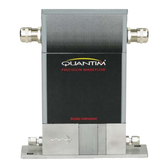
Quantim Low Flow Coriolis
Precision Mass Flow Measurement and Control
IP66XP
Explosion Proof
Configuration
NEMA1 / IP40
General Purpose
Configuration
"Quantim Coriolis mass flow controllers
enable precision measurement and control with
maximum flexibility and lowest overall cost of ownership."
QmB Series IP40, IP66, IP66XP
NEMA 4X / IP66
Weather Proof
Configuration
Advertisement
Table of Contents
Troubleshooting

Related Manuals for Brooks Quantim QmB Series


Summary of Contents for Brooks Quantim QmB Series
- Page 1 Installation and Operation Manual X-CM-QmB-eng Part Number: 541B029AAG QmB Series IP40, IP66, IP66XP June, 2011 ® Brooks Quantim Low Flow Coriolis Precision Mass Flow Measurement and Control NEMA1 / IP40 General Purpose Configuration NEMA 4X / IP66 Weather Proof Configuration...
- Page 2 Read before proceeding! Brooks Instrument designs, manufactures and tests its products to meet many national and international standards. These products must be properly installed, operated and maintained to ensure they continue to operate within their normal specifications. The following instructions must be adhered to and integrated into your safety program when installing, operating and maintaining Brooks Instrument products.
- Page 3 We appreciate this opportunity to service your flow measurement and control requirements with a Brooks Instrument device. Every day, flow customers all over the world turn to Brooks products for solutions to their gas and liquid low-flow applications. Brooks provides an array of flow measurement and control products for various industries from biopharmaceuticals, oil and gas, fuel cell research and chemicals, to medical devices, analytical instrumentation, semiconductor manufacturing, and more.
-
Page 4: Quick Start Instructions Ip40 - For Liquid Service
Installation and Operation Manual X-CM-QmB-eng Part Number: 541B029AAG QmB Series IP40, IP66, IP66XP June, 2011 Quick Start Instructions IP40 - For Liquid Service Horizontal Mounting Vertical Mounting QS-1... -
Page 5: Quick Start Instructions Ip40 - For Gas Service
Installation and Operation Manual X-CM-QmB-eng Part Number: 541B029AAG QmB Series IP40, IP66, IP66XP June, 2011 Quick Start Instructions IP40 - For Gas Service WARNING Operating Procedure: Do not operate this instrument outside the specifications listed in Section 1 of this manual. Before bringing the unit into operation, make sure all fluid connections have been correctly tightened and that all electrical connections have been made. -
Page 6: Quick Start Instructions Ip66
Installation and Operation Manual X-CM-QmB-eng Part Number: 541B029AAG QmB Series IP40, IP66, IP66XP June, 2011 Quick Start Instructions IP66 QS-3... -
Page 7: Quick Start Instructions Ip66Xp
Installation and Operation Manual X-CM-QmB-eng Part Number: 541B029AAG QmB Series IP40, IP66, IP66XP June, 2011 Quick Start Instructions IP66XP D-CONNECTOR PINOUTS FUNCTION Setpoint Common 0-5 Vdc Flow Signal Output Alarm Output * 4-20 mA Flow Signal Output +14 Vdc to _27 Vdc Power Supply Not Used * 4-20 mA Setpoint Input (+) 0-5 Vdc Setpoint Input (+) -
Page 8: Quick Start Instructions For Connecting Hart On 4-20 Mamp I/O
Quick Start Instructions for Connecting HART on 4-20 mAmp I/O Refer to the X-Qm-HART Installation and Operation Manuals for complete wiring of a Brooks Quantim for HART interface. HART Communications is provided on the Primary Output of the Brooks Quantim device. Connecting a HART Communicator, or any HART modem, requires a connection between pins 4 and 1 as shown below. - Page 9 Installation and Operation Manual X-CM-QmB-eng Part Number: 541B029AAG QmB Series IP40, IP66, IP66XP June, 2011 Proper wiring of a Brooks Quantim Explosion Proof NEMA 4X / IP66XP DB15 Connector 14-27 Quick Start Instructions for Connecting Alarm Output Alarm Output Option 1 - Relay...
- Page 10 Installation and Operation Manual X-CM-QmB-eng Part Number: 541B029AAG QmB Series IP40, IP66, IP66XP June, 2011 THIS PAGE WAS INTENTIONALLY LEFT BLANK QS-7...
-
Page 11: Table Of Contents
Installation and Operation Manual Contents X-CM-QmB-eng Part Number: 541B029AAG QmB Series IP40, IP66, IP66XP June, 2011 Section Page Number Number Quick Start Instructions Quick Start Instructions IP40 - For Liquid Service ................QS-1 Quick Start Instructions IP40 - For Gas Service ................QS-2 Quick Start Instructions IP66 ...................... - Page 12 2-3 Horizontal Right Side Up Installation ....................2-5 2-4 Vertical Flow Up Installation ........................ 2-6 2-5 Proper Wiring of a Brooks QmB IP66XP NEMA 4X ................2-8 2-6 Alarm Output Wiring Options ....................... 2-8 2-7 Wire Color Codes for 'D' Connector Assembly ................... 2-10 3-1 Location of LEDs ..........................
-
Page 13: Section 1 Introduction
Appendices Back Cover Warranty, Local Sales/Service Contact Information The Quality System at Brooks Instrument conforms to the quality standards set forth in ISO 9001. This instruction manual is intended to provide the user with all the information necessary to install, operate and maintain the Brooks Quantim Mass Flow Meters and Controllers. -
Page 14: Performance Specifications
Installation and Operation Manual Section 1 Introduction X-CM-QmB-eng Part Number: 541B029AAG QmB Series IP40, IP66, IP66XP June, 2011 1-3 Performance Specifications Performance Specifications: Flow: Liquid Flow Specifications, Metric Units Minimum Maximum Flow Nominal Flow Minimum Full Measurable Rate Rate Scale Flow Quantim Product... - Page 15 Installation and Operation Manual Section 1 Introduction X-CM-QmB-eng Part Number: 541B029AAG QmB Series IP40, IP66, IP66XP June, 2011 Gas Flow Limits Air, 70 F (21 C), 14.5 psi (1 bar) pressure drop 100,000 Size 4 Meter Size 4 Controller 10,000 Size 3 Meter Size 3 Controller Size 2 Meter...
- Page 16 Installation and Operation Manual Section 1 Introduction X-CM-QmB-eng Part Number: 541B029AAG QmB Series IP40, IP66, IP66XP June, 2011 Repeatability ± 0.05% or ± [0.5 x (zero stability/flowrate) x 100]% of rate whichever is greater Device Leak Integrity Elastomer Sealed Device: Outboard 1 x 10 atm.
- Page 17 ± 0.5°C or ± 1.0°F Notes QMBC - Brooks Quantim controller with integral control valve. QMBM - Brooks Quantim meter (no valve). The nominal flow rate is the flow rate at which water at reference conditions causes approximately 1 bar of pressure drop or the laminar to turbulent transition flow whichever is lower.
-
Page 18: Dimensions
Installation and Operation Manual Section 1 Introduction X-CM-QmB-eng Part Number: 541B029AAG QmB Series IP40, IP66, IP66XP June, 2011 Physical Specifications Materials of Construction: Process Wetted: 316L, 316L VAR, High Alloy Ferritic Stainless and 17-7PH Optional: Hastelloy sensor tube. Process Seals: ®... - Page 19 Additional Functions and Outputs Damping: Factory set time constant from 0 to 10 seconds. Alarms and Warnings: Alarms accessed via HART or the Brooks Service Tool can be configured (13) to monitor the following variables • Mass Flow • Density •...
- Page 20 Installation and Operation Manual Section 1 Introduction X-CM-QmB-eng Part Number: 541B029AAG QmB Series IP40, IP66, IP66XP June, 2011 Certifications and Approvals IP40 Series Non Incendive/ Non Sparking United States and Canada- UL Recognized E73889, Vol. 3, Sect. 3. Non Incendive , Class I, Division 2, Groups A, B, C and D; T4 Per UL 1604, UL 508 and CSA 22.2 No.
- Page 21 Do not open when an explosive atmosphere may be present. Environmental effects EMC effects: The Brooks Quantim series meets the requirements of the EMC directive 89/336EEC per EN 50081-2 and EN 61326-1. To meet these specifications, the Brooks Quantim device must be directly connected to a low impedance (less than 1 Ohm) earth ground.
- Page 22 Installation and Operation Manual Section 1 Introduction X-CM-QmB-eng Part Number: 541B029AAG QmB Series IP40, IP66, IP66XP June, 2011 1-4 Dimensions .594 15.10 3.060 77.72 .750 19.05 .003 .594 15.09 .003 .742 18.86 .594 15.10 .594 15.09 .003 .003 .003 .594 15.10 .594 15.09...
-
Page 23: D-Connector Electrical Pin Connections
Installation and Operation Manual Section 1 Introduction X-CM-QmB-eng Part Number: 541B029AAG QmB Series IP40, IP66, IP66XP June, 2011 Figure 1-2 Dimensional Drawing QmB IP40 Figure 1-3 D-Connector Electrical Pin Connections Figure 1-4 Lay-In Dimensions Integral and Remote Valves 1-11... -
Page 24: Dimensional Drawing Qmb Ip40 With Remote Valve
Installation and Operation Manual Section 1 Introduction X-CM-QmB-eng Part Number: 541B029AAG QmB Series IP40, IP66, IP66XP June, 2011 Figure 1-5 Dimensional Drawing QmB IP40 with Remote Valve Figure 1-6 Dimensional Drawing QmB IP66 1-12... -
Page 25: Dimensional Drawing Qmb Ip66Xp
Installation and Operation Manual Section 1 Introduction X-CM-QmB-eng Part Number: 541B029AAG QmB Series IP40, IP66, IP66XP June, 2011 Figure 1-7 Dimensional Drawing QmB IP66XP 1-13... - Page 26 Installation and Operation Manual Section 1 Introduction X-CM-QmB-eng Part Number: 541B029AAG QmB Series IP40, IP66, IP66XP June, 2011 THIS PAGE WAS INTENTIONALLY LEFT BLANK 1-14...
-
Page 27: Section 2 Installation
If the packing case is damaged, the local carrier should be notified at once regarding their liability. A report should be submitted to your nearest Product Service Department. Brooks Instrument 407 W. Vine Street P.O. Box 903 Hatfield, PA 19440 USA... -
Page 28: Return Shipment
This documentation is required before any Brooks personnel can begin processing the equipment. Copies of the forms can be obtained from any Brooks Instrument agent or on-line at www.brooksinstrument.com listed under the Support button. -
Page 29: Mechanical Installation
Installation and Operation Manual Section 2 Installation X-CM-QmB-eng Part Number: 541B029AAG QmB Series IP40, IP66, IP66XP June, 2011 WARNING Any rotation of the inlet or outlet fitting during installation of a metal seal device may result in a leak. Always use two (2) wrenches when attaching gas lines to prevent rotation. -
Page 30: Process Mounting
June, 2011 2-8 Process Mounting The Brooks Quantim will function in any orientation if the Coriolis sensor and the control valve remain filled with process fluid. Entrapped gas in a liquid application and entrapped liquid in a gas application should be prevented as it may disturb the Coriolis sensor and the control valve. -
Page 31: Horizontal Inverted Installation
June, 2011 Horizontal Mounting If installing the Brooks Quantim in a horizontal orientation, liquids should flow in the direction of the flow arrow. Situations of entrapped gas in the liquid process should be avoided. In liquid flow applications, it is... -
Page 32: Electrical Interfacing
June, 2011 Vertical Mounting If the Brooks Quantim is installed in a vertical orientation, for use in a liquid application liquid should flow upwards through the instrument to help minimize errors due to entrapped gas (See Figure 2-4). For gas flow vertical orientation, flow up or down is acceptable. - Page 33 Installation and Operation Manual Section 2 Installation X-CM-QmB-eng Part Number: 541B029AAG QmB Series IP40, IP66, IP66XP June, 2011 Power Supply (Pin 5 and Pin 9) Both Mass Flow Meter and Controller models are connected via Pins 5 (+14 to +27 Vdc) and 9 (power supply common) on the customer connector.
-
Page 34: Alarm Output Wiring Options
X-CM-QmB-eng Part Number: 541B029AAG QmB Series IP40, IP66, IP66XP June, 2011 Figure 2-5 Proper Wiring of a Brooks QmB IP66 NEMA 4X Alarm Output Option 1 - Relay Alarm Output Option 2 - TTL PIN 5 14 - 27 Vdc Power Source... -
Page 35: Interconnection With Peripheral Equipment
QmB Series IP40, IP66, IP66XP June, 2011 2-10 Interconnection with Peripheral Equipment Quantim Meter/Controller and Brooks Instrument Models 0152, 0154 or 0254 interconnection. The following cables are available for connection of the Quantim Mass Flow Meter/Controller to the Brooks Microprocessor Control & Read-out Unit: Models # 0152, 0154 or 0254 Length: 3ft (1m);... -
Page 36: Wire Color Codes For 'D' Connector Assembly
Installation and Operation Manual Section 2 Installation X-CM-QmB-eng Part Number: 541B029AAG QmB Series IP40, IP66, IP66XP June, 2011 Figure 2-7 Wire Color Codes for 'D' Connector Assembly 2-10... -
Page 37: Section 3 Operation
Quantim Helpdesk at Brooks Instrument. Customer Service The Brooks Helpdesk is available to assist with start-up if you experience issues you cannot solve on your own. You will be asked to provide the model code and serial number of your Brooks equipment, which will assist us in answering your questions. -
Page 38: Zero Adjustment
June, 2011 3-2 Zero Adjustment After the Brooks Quantim has been fully installed, you must perform the zeroing procedure. This procedure ensures that the instrument responds properly to zero flow condition and sets a baseline for flow. To perform the zeroing operation on the meter/controller, use the ZERO button, which is located on top right hand side (outlet side) of the instrument. - Page 39 Installation and Operation Manual Section 3 Operation X-CM-QmB-eng Part Number: 541B029AAG QmB Series IP40, IP66, IP66XP June, 2011 Zero Procedure 1. Prepare the instrument for zeroing: a. Install the instrument according to the instructions in this manual. b. Power-up sequence. Isolate device from flow pressure when applying power.
-
Page 40: Calibration Procedure
3-3 Calibration Procedure The Quantim calibration is not described in this manual. If your Quantim requires calibration, please contact one of the Brooks Instrument locations for technical assistance (See Back Cover for Contact Information). Or visit our website: www.BrooksInstrument.com/Service & Support. -
Page 41: Section 4 Maintenance
Installation and Operation Manual Section 4 Maintenance X-CM-QmB-eng Part Number: 541B029AAG QmB Series IP40, IP66, IP66XP June, 2011 4-1 General There are no routine maintenance procedures required to keep the Quantim device in good operating condition. It is however, very important to keep the fluid entering the Quantim clean, and as a result periodic replacement of the inlet guard filter is recommended at a frequency determined by the cleanliness of the fluid. -
Page 42: Troubleshooting
Installation and Operation Manual Section 4 Maintenance X-CM-QmB-eng Part Number: 541B029AAG QmB Series IP40, IP66, IP66XP June, 2011 4-2 Troubleshooting System Checks WARNING Internal seals and component alignments are extremely critical within this device. Improper servicing of your Quantim can cause malfunction of the device and/or personal injury. - Page 43 Pressure drop or inlet pressure Adjust pressure to original deviates form calibrated values. specifications. Valve out of adjustment. Contact Brooks Instrument. Unstable inlet pressure. Check external pressure regulator. Defective PC board. Contact Brooks Instrument. Valves are tuned digitally and Operate Quantim at specified mechanically for a particular ΔP.
- Page 44 Chemical deposits. Institute regular PM back flushing. Poor filtration of process fluid. Install proper filtration. Valve out of adjustment Contact Brooks Instrument. (applicable to Controller). Valve out of adjustment Valve guide spring failure Contact Brooks Instrument. (applicable to Controller).
- Page 45 (nitrogen or clean dry air) at a pressure near the process operating pressure. d. If the output signal does not zero properly, please contact Brooks Instrument for technical asistance. 3. For a MFC connect a 0-5 Vdc source to Pin 8 and return to Pin 1 or connect 0-20 mA source to Pin 7 and return to Pin 1.
-
Page 46: Bench Troubleshooting Circuit
6. If the Quantim is functioning correctly, the problem may lie elsewhere in the flow system. Re-verify the installation as well as the upstream/downstream fluid system configuration. 7. Please contact Brooks Instrument for further assistance in troubleshooting. Refer to the back cover of this manual for contact information. -
Page 47: External Valve Service
Installation and Operation Manual Section 4 Maintenance X-CM-QmB-eng Part Number: 541B029AAG QmB Series IP40, IP66, IP66XP June, 2011 4-3 External Valve Service Valve Disassembly The numbers in () refer to the parts in the exploded view diagram Figure 4-2. 1. Remove valve nut, item (9). 2. -
Page 48: Parts List
10. Install the vavle nut, item(10) hand tight (snug). 11. Pressure and leak test to local standards. Note: Standard Brooks Instrument pressure test is 1.5 times the design pressure marked on the valve and a helium leak test at 1 x10 bar .cc/s... -
Page 49: Exploded Diagram Of Valve Assembly
Installation and Operation Manual Section 4 Maintenance X-CM-QmB-eng Part Number: 541B029AAG QmB Series IP40, IP66, IP66XP June, 2011 Figure 4-3 Exploded Diagram of Valve Assembly Figure 4-4 Valve Torque Pattern... - Page 50 Installation and Operation Manual Section 4 Maintenance X-CM-QmB-eng Part Number: 541B029AAG QmB Series IP40, IP66, IP66XP June, 2011 THIS PAGE WAS INTENTIONALLY LEFT BLANK 4-10...
- Page 51 Part Number: 541B029AAG QmB Series IP40, IP66, IP66XP June, 2011 TRADEMARKS Brooks ..............Brooks Instrument, LLC Brooks Service Tool ..........Brooks Instrument, LLC Quantim ..............Brooks Instrument, LLC HART ..........HART Communications Foundation Hastelloy ..............Haynes International Kalrez ............ DuPont Performance Elastomers Viton ............
- Page 52 BROOKS SERVICE AND SUPPORT Brooks is committed to assuring all of our customers receive the ideal flow solution for their application, along with outstanding service and support to back it up. We operate first class repair facilities located around the world to provide rapid response and support.
Need help?
Do you have a question about the Quantim QmB Series and is the answer not in the manual?
Questions and answers