Advertisement
Quick Links
Quick Start Guide
Before operating the unit, please read this manual thoroughly and
keep it for future reference.
Please access our website and download necessary IPAdminTool first:
http://www.rivatech.de/en/downloads/software
NC36262IR11-2015-A
About the manuals
This manual provides the instructions for the quick installation
and the basic configuration of your IP device. For more detailed
information about the configuration, refer to the device's
installation guide and the web page manual.
Part names and functions
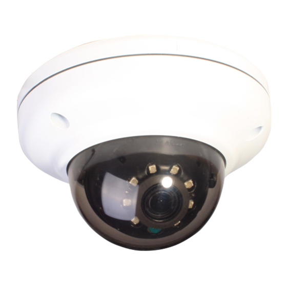
Please check the name and the position of each part by
referring to the following image.
*Installing a ferrite
core is highly
recommended to
reduce high frequency
noise level.
F/D Button
LAN Cable Connector
DC 12V Power Connector
Ambient Light Sensor: Used to detect the level or the intensity
of light for day/night transition. Thus, the sensor should not be blocked
by any object.
F/D Button: This factory default button restarts the device or
resets it to the factory default settings. For restart, press the
button only for 2 seconds while the device is powered on, and
for factory default, press the button for 10 seconds while the
device is powered on. Then, wait for the system to reboot.
mircoSD/SDHC Card Slot: a card up to 32GB supported. Class 4
or the above is recommended for HD recording.
LAN Cable Connector: Connect an RJ-45 LAN cable for 10/100
Base-T Ethernet (PoE supported)
DC 12V Power Connector: Connect the provided DC 12V
adaptor for power supply unless it is PoE powered.
Installation
There is only one type of mounting explained in this manual. Refer
to the device's installation guide for more various mounting types.
SD BOOT
Micro SD
SD BOOT
Ambient
Light Sensor
micro SD/SDHC
Card Slot
Gasket
O-ring
M4x30 screw
1) Place the installation template included in the package on a
desired installation surface.
2) Drill two holes for the plastic anchors based on the template
paper, a bigger hole for the cable lines, and insert the plastic
anchors into the two drilled holes.
3) Attach the provided gasket to the bottom of the camera body
for the prevention of water permeation.
4) Detach the dome cover from the camera body by loosening
the three screws with the provided L wrench (2.5mm).
5) Insert the two provided O-rings to the screws (M4x30) by
referring to the image at the bottom of the left side.
6) Take the camera to the installation surface, and connect the
LAN cable and the power cable dropped from the ceiling to the
corresponding connectors on the camera.
7) Align the screw holes on both sides of the camera body with
the plastic anchors on the installation surface, insert the screws
prepared at step 5 into the screw holes on the camera body,
and tighten them into the plastic anchors with a screw driver.
8) Adjust the angle of the camera. Refer to the section,
Adjusting angle of camera for more details.
9) Reattach the dome cover to the camera body by aligning the
alignment marks on both the dome cover and the camera body.
10) Once the two are properly aligned, tighten the screws on
the dome cover into the camera body with the provided L
wrench for the firm attachment. Then, remove the protection
film from the dome cover.
CAUTION
Do not forcefully pull or shake the dome cover as it is linked to the
camera body with a safety wire.
CAUTION
To prevent from damage, place the camera on a stable and non-
vibrating surface.
Adjusting angle of camera
Gimbal Bracket
Gimbal
Tilt Stopper
Inner
Liner
CAUTION
The ambient light sensor shall be uncovered for its normal
operation. Thus, be careful not to make the ambient light sensor
hidden by the dome cover when adjusting the camera angle.
NOTE
Tighten the tilt stopper after the angle is completely adjusted.
A. To pan, rotate the panning part of
the gimbal bracket horizontally by
holding the inner liner of the
camera.
(The panning range is limited to 358 degrees.)
B. To tilt, tilt the gimbal by referring
to the image on the left.
C. For the horizontal rotation of the
lens, rotate the inner liner clockwise
or counter-clockwise.
(The rotating range is limited to 358 degrees.)
Advertisement

Summary of Contents for Riva RC362HD
- Page 1 1) Place the installation template included in the package on a Quick Start Guide desired installation surface. 2) Drill two holes for the plastic anchors based on the template paper, a bigger hole for the cable lines, and insert the plastic Before operating the unit, please read this manual thoroughly and anchors into the two drilled holes.
- Page 2 Setting up network environment SETUP Page The default IP address of the device is 192.168.XXX.XXX. Users can To setup the device configuraiton: identify the IP address of the device by converting the MAC 1) Click the Setup button on the upper left corner of the web page. address’s hexadecimal numbers.


Need help?
Do you have a question about the RC362HD and is the answer not in the manual?
Questions and answers