Table of Contents
Advertisement
Quick Links
Advertisement
Table of Contents

Related Manuals for Riva RC3502HD-5311


Summary of Contents for Riva RC3502HD-5311
-
Page 1: Installation Guide
RC3502HD-5311 Installation Guide www.rivatech.de... -
Page 2: Information To User
INFORMATION TO USER CAUTION RISK OF ELECTRIC SHOCK, DO NOT OPEN CAUTION: TO REDUCE THE RISK OF ELECTRIC SHOCK, DO NOT REMOVE COVER (OR BACK). NO USER SERVICEABLE PARTS INSIDE. REFER SERVICING TO QUALIFIED SEERIVCE PERSONEL. This symbol is intended to alert the user to the presence of un- insulated “dangerous voltage”... -
Page 3: Table Of Contents
Table of Contents 1. FEATURES ................5 2. PACKAGE CONTENTS ..............7 3. PART NAMES ................8 4. INSTALLATION ................ 10 4.1. Installation Template ..............11 4.2. Setting the Lens Position .............. 12 4.3. Setting the Image Attribute ............12 5. - Page 4 APPENDIX (D): HEXADECIMAL-DECIMAL CONVERSION TABLE ..... 27 REVISION HISTORY ............... 28 www.rivatech.de...
-
Page 5: Features
01A.08 1.FEATURES Camera Full HD outdoor dome IP camera (Vandal proof) High quality compression in real time streaming 1/2.7” High Quality CMOS Image Sensor True Day / Night (ICR) Improvement of color rolling suppression Remote Zoom/Focus Control(One Click AF) Streaming ... - Page 6 01A.08 Additional Features Micro SD card supported PoE supported (Camera and Fan) Built-in Video Content Analysis IP66 certified SDK (Software Development Kit) provided Fan/Heater unit (heater function only with external power supply) * When VCA is activated, frame rate is limit to max15fps@1080p. Limitations are based on V.1.5.0 firmware release and could be changed without notice.
-
Page 7: Package Contents
01A.08 2. PACKAGE CONTENTS Unpack carefully and handle the equipment with care. The packaging contains: Camera DC power adaptor DC Jack Cable 9-pin and 2-pin terminal block Video out cable Screws and anchors Hex wrench driver Installation template Quick installation guide Silicon waterproof band Clamping core To prevent electromagnetic interference... -
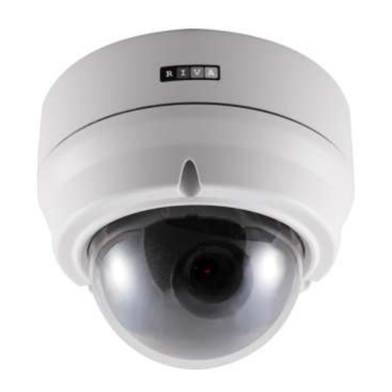
Page 8: Part Names
01A.08 3. PART NAMES * Models herein and their appearance are subject to change without any prior notice. 1. Fan The fan and heater (underneath the black panel) are implemented for controlling temperature and moisture of the internal device. - Page 9 01A.08 4. Video output, audio and IO terminal connector A 9-pin terminal block is included in the device package. Connect this terminal block into this connector for cable connection of video output, audio input/output and digital input/output. Refer to 5.1. Connector for more details.
-
Page 10: Installation
01A.08 4. INSTALLATION Place the installation template that is provided in the package on the desired position of installation. Attach the waterproof silicon band on the bottom plate of the device. Drill three holes template and insert anchor blocks into the holes. Fasten the camera with screws. -
Page 11: Installation Template
01A.08 The camera may fall off the ceiling even after the proper installation and mounting. To prevent any accident, make sure the ceiling is firm and stable enough to support the camera. If any reinforcement Caution is needed, consult with your safety personnel and proceed with the installation. -
Page 12: Setting The Lens Position
01A.08 4.2. Setting the Lens Position Set the lens position and adjust the zoom and focus by performing procedures as below. 1) Remove the dome cover. 2) Adjust the lens to the desired position by manually moving its body in the following directions. -
Page 13: Connections
Reset 01A.08 5.CONNECTIONS N / A N / A N / A N / A VIDEO AUDIO DC12V ETHERNET MICRO SD N / A N / A 1 Audio input/output The camera has a mono audio input and a mono audio output. Since the output power N / A N / A for the audio is low, an amplifier speaker is needed for a clearer sound (Do not use a... - Page 14 01A.08 Do not exceed the maximum input voltage or relay rate. Caution Internal Internal Output of Output of Sensor Sensor Relay Type Voltage Type 3 Alarm (DO) connection Only the relay type is supported. Relay Rating: Max 24VDC 50mA Do not exceed the maximum relay rating. Caution Internal Device...
- Page 15 01A.08 4 Video input/output The camera provides 1 video out. Please note that the analog video signal is only 3 minutes present after pushing the PAL/NTSC button and go back automatically to none video output mode (only installation process). Video Black 5 LAN connection This is a RJ45 LAN connector for 10/100 Base-T Ethernet.
-
Page 16: Configuration
01A.08 6.CONFIGURATION 6.1.Set up network environment The default IP address of the device is 192.168.XXX.XXX. Users can identify the IP address of the device from converting the MAC address’s hexadecimal numbers, which is attached to the device. Be sure that the device and PC are on a same area network before running the installation. -
Page 17: Custom Ip Environment
01A.08 2. Start the Microsoft® Internet Explorer web browser and enter the address of the device. 3. Web streaming and device configurations are supported through ActiveX program. When the ActiveX installation window appears, authorize and install the ActiveX. 6.1.2. Custom IP Environment IPAdminTool and the manual are provided on USB stick or can download from homepage. -
Page 18: View Video On Web Page
01A.08 Give new unique IP address in PC environment Info last two sets and mirror other information in other boxes 3. In the IP Setup’s window, information under ‘Local Network information’ displays the user/PC’s network area information. Those information need to be incorporated to the IP Address, Subnet Mask, Gateway, and DNS boxes, except the last 2 sets of IP Address, which are to be the unique numbers for the device. - Page 19 01A.08 2. Setup.exe installation link or pop-up window appears, depends on Microsoft® Internet Explorer version. Proceed with rest of setup installation. 3. Follow the instructions of the dialog boxes and complete the installation. Once the installation is complete, start the web browser again and check if video stream is displayed in the main view frame.
-
Page 20: View Video Using Ipadmin Tool
01A.08 6.2.1. View video using IPAdmin Tool IPAdminTool automatically searches all activated network encoders and IP cameras and shows the product name, IP address, MAC address and etc. IPAdminTool is provided on USB stick or can download from homepage. www.rivatech.de 1. -
Page 21: Reset
01A.08 6.3. Reset 1. Push the Reset button and hold for 1~2 seconds. 2. Wait for the system to reboot. 6.4. Factory Default If you reset your device to the factory default setting, all parameters including the IP address will be initialized. For the Factory Default reset: 1. -
Page 22: Appendix (A): Specifications
01A.08 APPENDIX (A): SPECIFICATIONS Summary Camera Module Image Sensor 1/2.7” 1080p CMOS Effective 1920x1080 CMOS Pixels Scanning Progressive scanning system Resolution 1920 x 1080 ELECTRIC Min. Color: 0.5 lux, F1.2 Illumination BW: 0.001 lux, F1.2 AGC Control Auto 3.0~9.0mm Vari-Focal F1.2 Lens Remote Zoom / Focus Control (One-click AF) Day &... -
Page 23: Electrical Characteristics
01A.08 * When VCA is activated, only one camera stream will be available and frame rate is limited to 15fps@1080p. Limitations are based on V.1.3.0 firmware release and could be changed without notice. Electrical Characteristics Power Source DC 12V / PoE IEEE802.3af (Class 0) 0.7A @ DC12V / 8.4W (Heater Off) Power Consumption 1.5A @ DC12V / 18W (Heater On) -
Page 24: Appendix (B): Power Over Ethernet
01A.08 APPENDIX (B): POWER OVER ETHERNET The Power over Ethernet (PoE) is designed to extract power from a conventional twisted pair Category 5 Ethernet cable, conforming to the IEEE 802.3af Power-over- Ethernet (PoE) standard. IEEE 802.3af allows for two power options for Category 5 cables. The PoE module signature and control circuit provides the PoE compatibility signature and power classification required by the Power Sourcing Equipment (PSE) before applying up to 15W power to the port. -
Page 25: Power Classification
01A.08 Power classification The PoE Power Class supported by the IP device is Class 0. Class Usage Minimum Power Levels Maximum Power Levels at Output at the PSE the Powered Device Default 15.4W 0.44 to 12.95W Unlike the other way, disconnecting PSE or PoE doesn’t reboot the device as long as a power adaptor is connected. -
Page 26: Appendix (C): Dimensions
01A.08 APPENDIX (C): DIMENSIONS (Unit: mm) www.rivatech.de... - Page 27 01A.08 APPENDIX (D): HEXADECIMAL- DECIMAL CONVERSION TABLE Refer to the following table when you convert the MAC address of your device to IP address. Hex Dec Hex Dec Hex Dec Hex Dec Hex Dec Hex Dec Hex Dec 94 148 25 37 4A 74 6F 111...
-
Page 28: Revision History
01A.08 REVISION HISTORY MAN# DATE(M/D/Y) Comments 01A.01 03/05/2012 Created 01A.02 03/13/2012 Modified PoE Compatibility, with power adaptor 01A.03 05/02/2012 Modified power, reset, and factory default 01A.04 06/01/2012 Power consumption, illumination variable update 01A.05 06/12/2012 Setup, Video, PAL/NTSC function update 01A.06 06/25/2012 DI/DO specification corrected 01A.07...
Need help?
Do you have a question about the RC3502HD-5311 and is the answer not in the manual?
Questions and answers