
Related Manuals for Reed Instruments R5020


Summary of Contents for Reed Instruments R5020
- Page 1 R5020 AC Clamp Meter Instruction Manual 1.800.561.8187 information@itm.com www. .com...
-
Page 2: Table Of Contents
Table of Contents Introduction ....................3 Product Quality ................... 3 Safety ......................3-4 Features ...................... 4 Included ...................... 4 Specifications ..................5-6 Instrument Description ................7 Display Description ..................8 Operating Instructions ................9-12 Connecting the Test Leads ..............9 AC Current Measurements ..............9 AC/DC Voltage Measurements .............. -
Page 3: Introduction
Introduction Thank you for purchasing your REED R5020 AC Clamp Meter. Please read the following instructions carefully before using your instrument. By following the steps outlined in this manual your meter will provide years of reliable service. Product Quality This product has been manufactured in an ISO9001 facility and has been calibrated during the manufacturing process to meet stated product specifications. -
Page 4: Features
• Remove the battery if the meter is to be stored for a long period of time. • Always discharge capacitors and remove power from the device under test before performing diode, resistance, or continuity tests. • Voltage checks on electrical outlets can be difficult and misleading because of the uncertainty of connection to the recessed electrical contacts. -
Page 5: Specifications
Specifications AC Current Range: 40, 400A Accuracy: AC: ±(2.5% rdg. + 8 dgt.) Resolution: 0.01, 0.1A AC/DC Voltage Range: AC: 4, 40, 400, 600V DC: 400mV, 4, 40, 400, 600V Accuracy: AC: ±(1.8% rdg. + 8 dgt.) DC: ±(1.5% rdg. + 2 dgt.) Resolution: AC: 0.001, 0.01, 0.1, 1V DC: 0.1mV, 0.001, 0.01, 0.1, 1V... - Page 6 General Specifications Range Selection: Autoranging/Manual Display: 4.000 count LCD display Display Hold: Relative Mode: Diode Test: Continuity Check: Audible signal if resistance <150Ω Duty Cycle: Non-Contact Voltage Detector: Autoshut off: Yes (after 15 minutes) Power Supply: 2 x AAA Batteries Low Battery Indicator: Jaw Opening: 1.2"...
-
Page 7: Instrument Description
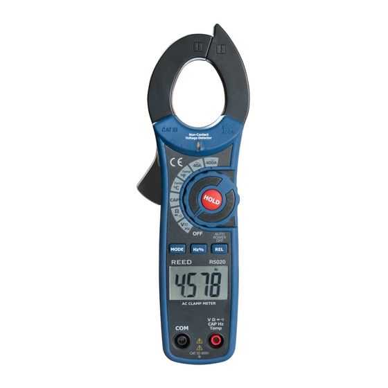
Instrument Description R5020 7. COM Input Jack 1. Current Clamp 2. Non-contact AC Voltage 8. Battery Cover Indicator Light 9. Data Hold Button 3. Clamp Trigger 10. Rotary Switch 4. MODE Selection Button 11. Relative Button 5. Frequency/Duty Cycle 12. VΩ CAP TEMP Hz Input Jack Selection Button 6. -
Page 8: Display Description
Display Description REL kM °C °F 1. AC/DC Indicator 2. Negative Reading Indicator 3. 4000 Count Main Display 4. Temperature Units 5. Low Battery Indicator 6. Units of Measurement 7. Relative Mode Indicator 8. Data Hold Indicator 9. Audible Continuity Indicator 10. -
Page 9: Operating Instructions
Operating Instructions Connecting the Test Leads Connect the red test lead to the VΩ Input Jack and the black test lead to the COM Input Jack. AC Current Measurements Warning: Disconnect the test leads before making clamp measurements. Set the rotary switch to the 400 or 40A range. -
Page 10: Resistance Measurements
Resistance Measurements Set the rotary switch to the Ω position. Connect the test leads to the meter (see Connecting the Test Leads section for details). Touch the test probe tips across the circuit or component under test as shown. Note: It is best to disconnect one side of the device under test so the rest of the circuit will not interfere with the reading. -
Page 11: Capacitance Measurements
Capacitance Measurements To avoid electric shock, disconnect power to the unit under test and discharge all capacitors before taking any capacitance measurements. Remove the batteries and unplug the line cords. Set the rotary function switch to the CAP position. Connect the test leads to the meter (see Connecting the Test Leads section for details). -
Page 12: Non-Contact Ac Voltage Measurements
Non-Contact AC Voltage Measurements Set the rotary function switch any measurement position. Place the tip of the meter to the hot conductor under test or the hot side of the electrical outlet. If AC voltage is present, the detector will light up. Note: The conductors in electrical cord sets are often twisted. -
Page 13: Battery Replacement
Battery Replacement Remove the 2x Phillips head screws that secure the battery cover. Remove the battery cover. Replace the 2 x AAA batteries. Properly secure the cover and tighten the screws. Applications Industrial maintenance teams performing scheduled and preventative maintenance on electro-mechanical equipment and systems. Facilities, building maintenance and electricians looking to troubleshoot electrical equipment installation problems. -
Page 14: Product Care
REED Instruments guarantees this instrument to be free of defects in material or workmanship for a period of one (1) year from date of shipment. During the warranty period, REED Instruments will repair or replace, at no charge, products or parts of a product that proves to be defective because of improper material or workmanship, under normal use and maintenance. -
Page 15: Product Support
Product Support If you have any questions on your product, please contact your authorized REED distributor or REED Instruments Customer Service by phone at 1-877-849-2127 or by email at info@reedinstruments.com. Please visit www.REEDINSTRUMENTS.com for the most up-to-date manuals, datasheets, product guides and software. - Page 16 TEST & MEASURE WITH CONFIDENCE CHECK OUT OUR LATEST PRODUCTS! 1.800.561.8187 information@itm.com www. .com...
Need help?
Do you have a question about the R5020 and is the answer not in the manual?
Questions and answers