
Related Manuals for Reed Instruments R5001


Summary of Contents for Reed Instruments R5001
- Page 1 R5001 LCR Meter Instruction Manual www.REEDINSTRUMENTS.com REED-Direct.ca info@REED-Direct.ca 1.800.561.8187...
-
Page 2: Table Of Contents
Table of Contents Introduction ....................3 Product Quality ................... 3 Safety ......................4 Features ...................... 4 Included ...................... 5 Specifications ..................5-10 Accuracy ...................6-10 Instrument Description ................11 Operating Instructions .................12-19 Power ON/OFF ..................12 Auto Power Off ..................12 Beep Function ..................12 Backlight .................... -
Page 3: Introduction
Product Support ..................22 Introduction Thank you for purchasing your REED R5001 LCR Meter. Please read the following instructions carefully before using your instrument. By following the steps outlined in this manual your meter will provide years of reliable service. -
Page 4: Safety
Safety This manual should be read and well understood before the instrument is used. • Never attempt to repair or modify your instrument. Dismantling your product, other than for the purpose of replacing batteries, may cause damage that will not be covered under the manufacturer's warranty. Servicing should only be provided by an authorized service center. • Do not operate in an explosive atmosphere. -
Page 5: Included
Included • Test Leads and Probes • Tweezers • Alligator Clips • Batteries Specifications Test Frequencies: 100/120/1k/10k/100kHz Test AC Signal Level: 0.6mVRMS typical Test Range (F=1kHz): L: 200µH to 2000H C: 2000pF to 2mF R: 20Ω to 200MΩ Primary Parameters Display: DCR: DC resistance Ls: Serial inductance Lp: Parallel inductance Cs: Serial capacitance Cp: Parallel capacitance Rs: Serial resistance Rp: Parallel resistance... -
Page 6: Accuracy
Accuracy Notes: • Measurement performed at the test socket. • Measurements performed after correct open and short calibration. • DUT and test leads must be properly shielded. • Q value is the reciprocal of DF. • Accuracies based within 10% to 100% of full scale of range; values outside of range should be used as reference only. • "---" means parallel or series measurement mode. Inductance @ Ta = 18 to 28°C (De) Frequency = 100 Hz/120 Hz Range Resolution Lx Accuracy DF Accuracy Measurement Mode 20.000mH 1µH 1.5% ±10d 1.5% ±50d Series 200.00mH 0.01mH 1.4% ±15d 1.4% ±50d Series... - Page 7 Frequency = 10kHz Range Resolution Lx Accuracy DF Accuracy Measurement Mode 200.00µH 0.01µH 1.8% ±10d 1.8% ±50d Series 2000.0uH 0.1µH 1.5% ±10d 1.5% ±50d Series 20.000mH 1µH 1.2% ±10d 1.2% ±50d Series 200.00mH 0.01mH 1.5% ±15d 1.5% ±50d 2000.0mH 0.1mH 2.0% ±10d 2.0% ±50d Parallel 20.000H 2.5% ±15d 2.5% ±50d Parallel Frequency = 100kHz Range Resolution Lx Accuracy DF Accuracy Measurement Mode 20.000µH...
- Page 8 Frequency = 1kHz Range Resolution Cx Accuracy DF Accuracy Measurement Mode 2000.0pF 0.1pF 3.5% ±15d 3.5% ±50d Parallel 20.000nF 1.0% ±10d 1.0% ±50d 200.00nF 0.01nF 0.9% ±10d 0.9% ±50d 2000.0nF 0.1nF 1.0% ±10d 1.0% ±50d Series 20.000µF 1.2% ±15d 1.2% ±50d Series 200.00µF 0.01µF 2.5% ±10d 2.5% ±50d Series 2000µF 1µF 4% ±20d 4% ±50d Series Frequency = 10kHz Range Resolution...
- Page 9 Resistance @ Ta = 18 to 28°C (De) Frequency = 100Hz/120Hz Range Resolution Rx Accuracy Measurement Mode 200.00Ω 0.01Ω 1.2% ±10d 2.0000kΩ 0.1Ω 0.8% ±5d 20.000kΩ 1Ω 0.9% ±5d 200.00kΩ 0.01kΩ 0.7% ±3d 2.0000MΩ 0.1kΩ 1.0% ±5d 20.000MΩ 1kΩ 2.2% ±10d 200.0MΩ 0.1MΩ 2.5% ±10d Frequency = 1kHz Range Resolution Rx Accuracy Measurement Mode 20.000Ω 1mΩ 1.2% ±10d 200.00Ω 0.01Ω...
- Page 10 Frequency = 100kHz Range Resolution Rx Accuracy Measurement Mode 20.000Ω 1mΩ 2.3% ±10d 200.00Ω 0.01Ω 1.5% ±5d 2.0000kΩ 0.1Ω 0.8% ±20d 20.000kΩ 1Ω 0.8% ±20d 200.00kΩ 0.01kΩ 1.5% ±10d 2.000MΩ 1kΩ 2.5% ±30d DC Resistance @ Ta = 18 to 28°C (De) Frequency = 100Hz/120Hz/1kHz/10kHz/100KHz Range Resolution Rx Accuracy Measurement Mode 200.00Ω 0.01Ω 1.8% ±10d 2.0000kΩ 0.1Ω 0.6% ±20d 20.000kΩ 1Ω...
-
Page 11: Instrument Description
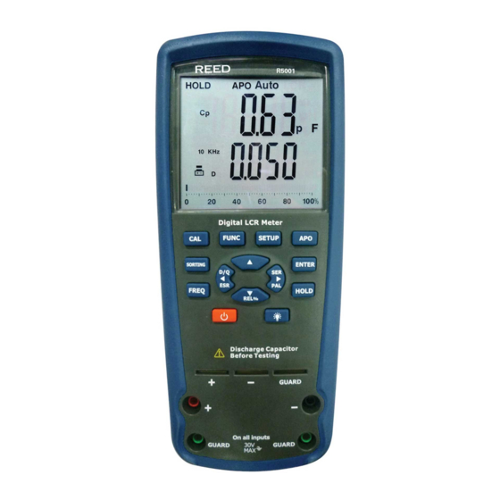
Instrument Description R5001 1. LCD Display 10. Setup Button 2. Function Button 11. Auto Power Off Button 3. Calibration Button 12. Up Button 4. Sorting Button 13. Enter Button 5. Frequency Button 14. Hold Button 6. Secondary Display/ 15. Parallel/Series/Right Button Left Button 16. Backlight Button 7. Power Button 8. Relative/Down Button... -
Page 12: Operating Instructions
Operating Instructions Power ON/OFF To turn the meter on or off, press the power button. By default, the meter is set to Auto LCR Smart mode with a test frequency of 1kHz. Auto Power Off To preserve battery life, the meter is programmed to turn off after 5 minutes of inactivity and 3 warning beeps. If a button is pushed during the three beeps, the meter will continue measuring. -
Page 13: Test Frequency Functions
Test Frequency Functions Test frequency can greatly affect the results of measurement readings, especially when measuring inductors and capacitors. This section provides some recommendations and suggestions to consider. Capacitance When measuring capacitance, selecting the right frequency is important in obtaining the most accurate results. Generally a 1kHz test frequency is used to measure capacitors that are 0.01μF or smaller. For capacitors that are 10μF or larger, a lower frequency of 120Hz is used. Following this trend, high-test frequencies are best for testing very low capacitance components. -
Page 14: Primary Impedance With Secondary Parameter Test
Primary Impedance with Secondary Parameter Test The default test mode for this meter is Auto-LCR Mode, which checks the type of impedance and automatically enters L/C/R Mode. The secondary parameter will follow the L/C/R measurement, meaning that (L+Q), (C+D)*, (R+θ)** are combined in one group respectively. Press the FUNC button to switch from Auto-LCR Mode to Auto-Lp Mode, Auto-Cp Mode, Auto-Rp Mode, and DCR Mode. Note: When Auto-Lp or Auto-Cp Mode is selected, the impedance measurement is auto ranging. -
Page 15: Capacitance
Capacitance Most capacitance measurements will obtain best results with parallel mode selected. The majority of capacitors have a very low dissipation factor (high internal resistance) compared to the impedance of the capacitance. In these cases, the paralleled internal resistance has negligible impact on the measurement. There will be some cases where series mode would be used for a capacitance measurement, or the readings will appear inaccurate. -
Page 16: Relative Mode
Relative Mode To reserve the current DUT readings (DCUR) on the primary display as a reference value (DREF), press the button. The ∆ symbol will then appear on the LCD screen indicating this function is now active. The secondary display will show the percentage of the relative value (REL%). Press the button again to show the reference value (DREF) on the primary display; the ∆ symbol will start to blink. REL% = (DCUR – DREF) / DREF x 100% Note: The percentage range is -99.9% to 99.9%. When the relative value is larger than double the reference value (DREF), the "OL%" symbol will appear on the secondary display. Press and hold down the button for approximately 3 seconds to exit relative mode and resume normal operation. -
Page 17: Resistance
Resistance When measuring resistance of devices, it is important to know that there are two types or ways of measurement. One type is DC resistance measurement. Another type is AC resistance measurement. The LCR meter provides both types of measurement. Before using the meter to measure resistance, please verify whether the DUT (device under test) requires DC or AC resistance measurement method. -
Page 18: Sorting Mode
Press the CAL button again and a 30 second countdown will appear on the screen. After the countdown is complete, a "PASS" or "FAIL" will show on the display. Press the CAL button a third time, and "SRT" will appear on the LCD screen, indicating to the user to put the shorting bar across the "+" and "-" input terminals. Press the CAL button a fourth time, and a 30 second countdown will appear on the screen. After the calibration procedure is finished a "PASS" or "FAIL" will appear on the LCD screen. Press the CAL button a fifth time and the calibration data will be saved if "PASS" was displayed for both the Open & Short calibrations. -
Page 19: Battery Replacement
Press the SETUP button and the "Range" symbol will fl ash on the display. Adjust the range setting by pressing the buttons Press the ENTER button save the range setting and proceed to the value setting. Press the buttons to select the fl ashing digit required for adjustment. Press the button to adjust the value of the digit. Press the ENTER button to save the value setting and proceed to the Tolerance setting. -
Page 20: Accessories And Replacement Parts
Accessories and Replacement Parts • FC-A23 Alligator Clip Set • FC-300 Fused Test Lead Set • R8888 Deluxe Hard Carrying Case • CA-05A Soft Carrying Case Don't see your part listed here? For a complete list of all accessories and replacement parts visit your product page on www.reedinstruments.com. Product Care To keep your instrument in good working order we recommend the following: • Store your product in a clean, dry place. -
Page 21: Product Warranty
REED Instruments guarantees this instrument to be free of defects in material or workmanship for a period of one (1) year from date of shipment. During the warranty period, REED Instruments will repair or replace, at no charge, products or parts of a product that proves to be defective because of improper material or workmanship, under normal use and maintenance. -
Page 22: Product Support
Product Support If you have any questions on your product, please contact your authorized REED distributor or REED Instruments Customer Service by phone at 1-877-849-2127 or by email at info@reedinstruments.com. Please visit www.REEDINSTRUMENTS.com for the most up-to-date manuals, datasheets, product guides and software. Product specifications subject to change without notice. - Page 23 TEST & MEASURE WITH CONFIDENCE CHECK OUT OUR LATEST PRODUCTS! www.REEDINSTRUMENTS.com REED-Direct.ca info@REED-Direct.ca 1.800.561.8187...
- Page 24 www.REEDINSTRUMENTS.com REED-Direct.ca info@REED-Direct.ca 1.800.561.8187...
Need help?
Do you have a question about the R5001 and is the answer not in the manual?
Questions and answers