
Related Manuals for Reed Instruments R5055


Summary of Contents for Reed Instruments R5055
- Page 1 R5055 1000A True RMS Digital Clamp Meter Instruction Manual 1.800.544.2843 www.calcert.com sales@calcert.com...
-
Page 2: Table Of Contents
Table of Contents Intoduction ....................3 Product Quality ................... 4 Safety ......................4 Electrical Symbols ..................5 Features ...................... 6 Included ...................... 6 Specifications ..................7-9 Instrument Description ................10 Display Description .................. 11 Operating Instructions .................12-19 AC/DC Current Measurements............12 Current Frequency Measurement ............ -
Page 3: Intoduction
Product Disposal and Recycling .............. 23 Product Support ..................24 Introduction Thank you for purchasing your REED R5055 1000A True RMS Digital Clamp Meter. Please read the following instructions carefully before using your instrument. By following the steps outlined in this manual your meter will provide years of reliable service. -
Page 4: Product Quality
Product Quality This product has been manufactured in an ISO9001 facility and has been calibrated during the manufacturing process to meet stated product specifications. If a certificate of calibration is required please contact the nearest authorized REED distributor or authorized Service Center. Please note an additional fee for this service will apply. -
Page 5: Electrical Symbols
Electrical Symbols Symbol Description Equipment protected throughout by double insulation or reinforced insulation Earth (ground) Warming or Caution Alternating current Direct current Continuity buzzer Diode Capacitance Alternating current or direct current Caution, possibility of electric shock Application around and removal from uninsulated hazardous live conductors is permitted Complies with European Union Standards Conforms to UL STD 61010-1, 61010-2-032, 61010-2-033,... -
Page 6: Features
Features • Measures AC/DC current/voltage, resistance, capacitance, frequency, duty cycle, and contact temperature • 6,000-count backlit LCD display and analog bargraph • Flexible current probe can expand AC current measurements up to 3000A (with R5065, sold separately) • Ergonomic design fits in your hand and can be used while wearing protective gloves •... -
Page 7: Specifications
Specifications AC/DC Current Range: 60, 600, 1000A Accuracy: AC/DC: ±(2% rdg. +5 dgt.) Resolution: 0.01, 0.1, 1A AC/DC Voltage Range: AC: 6, 60, 600, 1000V DC: 600mV, 6, 60, 600, 1000V Accuracy: AC: ±(1.0% rdg. +8 dgt.) DC: ±(0.5% rdg. +5 dgt.) Resolution: 0.1mV, 0.001V, 0.01V, 0.1V, 1V Resistance... - Page 8 Low Impedance (LoZ) AC Voltage Range: 600, 1000V Accuracy: ±(2% rdg. +5 dgt.) Resolution: 0.1, 1V Temperature Range: -40 to 1832°F (-40 to 1000°C) Accuracy: ±(1.0% rdg. + 4°F) ±(1.0% rdg. + 2°C) Resolution: 1°F, 1°C General Specifications Range Selection: Autoranging/Manual Low Impedance (LoZ): Low Pass Filter (LPF):...
- Page 9 Autoshut Off: Yes (after 15 mins) Flexible Current Probe (optional): Yes (R5065, Extends to 3000A) Power Supply: 3 x AAA batteries Low Battery Indicator: Jaw Opening: 1.7" (42mm), up to 1500 MCM Overvoltage Category: CAT. III 1000V, CAT. IV 600V Product Certifications: CE, ETL Operating Temperature:...
-
Page 10: Instrument Description
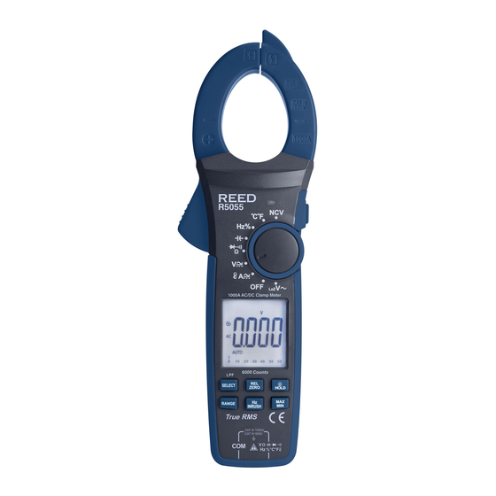
Instrument Description R5055 1000A AC/DC Clamp Meter 1. Current Clamp 7. Flashlight Button 2. Clamp Trigger 8. Rotary Function Switch 3. LCD Display 9. Flashlight LED Light 4. Function Buttons 10. Battery Cover 5. Non-Contact Voltage Sensor 11. Input Jacks 6. -
Page 11: Display Description
Display Description 10 11 12 13 14 15 1. Low Battery Indicator 13. Non-Contact Voltage Indicator 2. Inrush Current Measurement Indicator 14. Low Impedance Measurement Indicator 3. High Voltage Indicator 15. Units of Measurement 4. Auto Power Off Indicator 16. Flexible Current Probe Range 5. -
Page 12: Operating Instructions
When stable, push the Zero button to ensure accurate readings. Zeroing the meter removes DC R5055 offset from the measurement reading. Note: The Zero function works only when the dial is set to the DC current measurement position. -
Page 13: Ac/Dc Voltage Measurements
Press and hold the Hz/INRUSH button for 2 seconds to enter the Inrush current measurement mode. Turn on the device under test. The LCD will display the reading. NOTE: Inrush current is the highest AC current (True RMS) within 100ms of start time, as shown below. -
Page 14: Low Pass Filter (Lpf) Acv Measurement
Low Pass Filter (LPF) ACV Measurement While in AC voltage measurement mode, press and hold the SELECT button to enter the LPF ACV measurement mode. NOTE: Low Pass Filter can measure combined sine wave signals produced by inverters and variable frequency drives, as shown below. 2. -
Page 15: Resistance Measurement
Resistance Measurement NOTE: Remove power before making resistance measurements. Insert the black test lead into the negative COM terminal and the red test lead into the positive V terminal. Set the rotary function to the position. Press the SELECT button to switch to resistance measurement mode (Ω). -
Page 16: Capacitance Measurement
The LCD will display the reading. Forward voltage will indicate 0.5V to 0.8V. Reverse voltage will be indicated by "OL". Shorted devices will indicate near 0mV and an open device will be indicated by "OL" in both polarities. Black Black Probe Probe Probe... -
Page 17: Contact Temperature Measurement
Contact Temperature Measurement To avoid electric shock, before taking a contact temperature measurement disconnect both test probes from any source of voltage. Set the rotary function to the °C/°F position. Insert the included Temperature Probe into the negative COM and the positive V terminals, making sure to observe the correct polarity. -
Page 18: Auto And Manual Range
Auto and Manual Range When the meter is first turned on, it automatically goes into Auto Ranging mode. This automatically selects the best range for the measurement being made and is generally the best mode for most applications. For applications that require a manual range to be set, perform the following: Press the RANGE button. -
Page 19: Max/Min Measurement
MAX/MIN Measurement Press the MAX/MIN button to select the maximum reading as indicated by the "MAX" symbol. The Max value is updated when a new maximum data value has been attained. Press the MAX/MIN button again to select the minimum reading as indicated by the "MIN"... -
Page 20: Accessories And Replacement Parts
Accessories and Replacement Parts • R5400 Line Splitter • R2990 Thermocouple Adapter • R2920 Surface Thermocouple Probe • R2930 Right Angle Thermocouple Surface Probe • R2940 Air/Gas Thermocouple Probe • R2950 Immersion Thermocouple Probe • R2960 Needle Tip Thermocouple Probe •... -
Page 21: Ac Current Frequency Measurement With Flexible Probe
Turn on the flexible probe by setting the required current range. NOTE: When measuring current, center the conductor in the flexible current Probe. If possible, avoid taking R5055 measurements close to other R5065 Flex Clamp Current Probe current-carrying conductors. 1000A AC/DC Clamp Meter Set the rotary function switch to position. -
Page 22: Inrush Ac Current Measurement
Inrush AC Current Measurement Insert the flexible current probe into the negative COM terminal and the red test lead into the positive V terminal. Connect the probe's flexible tubing around the conductor under test. If you are opening the end of the flexible probe to make the connection, be sure to close and lock it back into place. -
Page 23: Product Care
REED Instruments guarantees this instrument to be free of defects in material or workmanship for a period of one (1) year from date of shipment. During the warranty period, REED Instruments will repair or replace, at no charge, products or parts of a product that proves to be defective because of improper material or workmanship, under normal use and maintenance. -
Page 24: Product Support
Product Support If you have any questions on your product, please contact your authorized REED distributor or REED Instruments Customer Service by phone at 1-877-849-2127 or by email at info@reedinstruments.com. Please visit www.REEDInstruments.com for the most up-to-date manuals, datasheets, product guides and software. - Page 25 TEST & MEASURE WITH CONFIDENCE CHECK OUT OUR LATEST PRODUCTS! 1.800.544.2843 www.calcert.com sales@calcert.com...
- Page 26 1.800.544.2843 www.calcert.com sales@calcert.com...
Need help?
Do you have a question about the R5055 and is the answer not in the manual?
Questions and answers