Table of Contents
Advertisement
Quick Links
Advertisement
Table of Contents

Related Manuals for Yetter Nutrient Pro 4000 Series


Summary of Contents for Yetter Nutrient Pro 4000 Series
- Page 1 4000 SERIES NUTRIENT PRO FERTILIZER COULTER OPERATOR’S / INSTALLATION INSTRUCTION MANUAL W/ PARTS IDENTIFICATION 2565-952 REV A 12/2020 YETTER MANUFACTURING CO. FOUNDED 1930 Colchester, IL 62326-0358 Toll free: 800/447-5777 309/776-3222 (Fax) Website: www.yetterco.com E-mail: info@yetterco.com...
-
Page 2: Foreword
WARRANTY POLICY Yetter Manufacturing warrants all products manufactured and sold by it against defects in material. This warranty being expressly limited to replacement at the factory of such parts or products as will appear to be defective after inspection. -
Page 3: Safety
SAFETY A brief description of signal words that may be used in this manual: CAUTION: Used as a general reminder of good safety practices or to direct attention to unsafe practices. WARNING: Denotes a specific potential hazard. DANGER: Denotes the most serious specific potential hazard. SAFETY PRECAUTIONS You can make your farm a safer place to live and work if you observe the safety precautions given. -
Page 4: Table Of Contents
TABLE OF CONTENTS FOREWORD…………………………………………………………….2 SAFETY……………………………………………………………….…3 TABLE OF CONTENTS/BOLT TORQUE..…………………………..4 GENERAL INFORMATION............5 – 6 ASSEMBLY INSTRUCTIONS…………………………………..7 – 11 OPERATION…………………………………………………….12 – 13 MAINTENANCE………………………………………………...14 – 16 PARTS IDENTIFICATION……………………………………..17 – 33 TROUBLESHOOTING……………………………………………..34 NOTES...................35 BOLT TORQUE READ THESE INSTRUCTIONS FIRST: 1. Improperly tightened bolts will result in damage, breakage, expense, and down time. 2. - Page 5 GENERAL INFORMATION PART NUMBERS AND DESCRIPTIONS – COULTER ASSEMBLIES PART NUMBER DESCRIPTION 18” RH NUTRIENT PRO COULTER WITH DRY KNIFE 4000-001 18” LH NUTRIENT PRO COULTER WITH DRY KNIFE 4000-002 18” RH NUTRIENT PRO COULTER WITH LIQUID KNIFE 4000-003 18” LH NUTRIENT PRO COULTER WITH LIQUID KNIFE 4000-004 20”...
-
Page 6: General Information
GENERAL INFORMATION Examine all equipment carefully for shipping damage or shortages. NOTE: Right & left hand designations are based on sitting in the tractor & facing forward. When you are behind the coulter looking forward, the right hand coulter is assembled with the blade & gauge wheel to the right hand of the arm assembly. The left hand coulter is assembled with the blade &... - Page 7 ASSEMBLY INSTRUCTIONS FOR CNH 1250/1255 PLANTERS (12 & 16 ROW) WARNING: NEVER WORK UNDER THE EQUIPMENT WHILE IN A RAISED POSITION WITHOUT USING SAFETY LOCK UPS. FAILURE TO DO SO MAY LEAD TO PERSONAL INJURY OR DEATH. STEP 1: Start by placing 2 U-bolts at each row, threads toward the ground, between the U-bolts used to mount that seed unit to the toolbar (see picture below labeled shim installation).
- Page 8 1 – 8, the 4000-260 RH MOUNT will be used on rows 9 – 16, & the shim will be used on rows 6 – 11. ASSEMBLY INSTRUCTIONS FOR CNH 1250/1255 PLANTERS 12 & 16 ROW CONT’D STEP 5: Install the LH CNH mount on row 2 & the RH CNH mount on row 11 (12 row planter) or row 15 (16 row planter). Install the LH coulter to the LH mount &...
-
Page 9: Assembly Instructions
ASSEMBLY INSTRUCTIONS (Toolbar Application) Step 1: Assemble the U-bolts, mounting plate, and hardware to the toolbar. Leave the hardware loose until the coulter is set to the correct spacing. Tighten the U-bolts first, then tighten the 5/8 horizontal bolt. 4000-040 Mount Kit 4000-041 Mount Kit 4000-042 Mount Kit 4000-043 Mount Kit... - Page 10 ASSEMBLY INSTRUCTIONS (Toolbar Application) 4000-046 Mount Kit 4000-047 Mount Kit 4000-048 Mount Kit 4000-101 -2 Degree Angle Shim Installation (Optional)
- Page 11 ASSEMBLY INSTRUCTIONS (ToolBar Application) Step 2: Assemble the coulter to the shank using the 2) ¾ X 2” bolts. Step 3: Attach the fertilizer hose to the tube on the fertilizer knife. When routing the hose use your best judgement to prevent excessive wear, pinching, or pulling.
-
Page 12: Operation
OPERATION The 4000 Nutrient Pro single disc fertilizer is designed for use in most planting and side dress conditions. Placement of fertilizer with the single disc fertilizer opener is recommended at 2”-4” from the row. The opener is designed to hold the blade at a set angle so the knife & fertilizer tube operate in the shadow of the blade. NEVER locate the opener to place fertilizer closer than 2”. - Page 13 OPERATION STEP 2: SETTING THE DEPTH Planter mounted 4000 Nutrient Pro assemblies are only adjustable by the depth control pin. If 4000 Nutrient Pro assemblies are to be used for side dressing or pre-plant, raise or lower the coulter assembly/shank at the toolbar as needed to achieve the desired depth.
-
Page 14: Maintenance
Alternative Lubricants Conditions in certain geographical areas may require special lubricants & lubrication practices which do not appear in the operator's manual. If there are any questions, consult Yetter Manufacturing Co. to obtain latest information and recommendation. Storing Lubricants Your machine can operate at top efficiency only if clean lubricants are used. - Page 15 MAINTENANCE BEARING REPLACEMENT INSTALLATION When assembling the closing wheels, bearing assembly and hubcap, be sure to align the grease transfer hole in the spoke wheel with the groove in the hubcap and hole in the hub to allow grease passage. Install/assemble the wheels, hubs and caps.
- Page 16 Clean machine thoroughly to remove all dirt, debris, fertilizer spatter, and crop residue, which would hold moisture and cause rusting. Inspect machine for worn or broken parts. See your Yetter Farm Equipment dealer during the off-season so that parts or service can be acquired when machine is not needed in the field.
-
Page 17: Parts Identification
4000-001 PARTS IDENTIFICATION ITEM PART NUMBER DESCRIPTION QUANTITY 2505-262 3/8-16 x 1 ½ CAR BOLT ZP 3/8 – 16 LOCK HEX NUT ZP 2520-255 18” COULTER, LESS KNIFE, RH 4000-140 4000-230 DRY FERTILIZER SPOUT W.A., RH 4000-370 RUBBER SHIM 4000-002 PARTS IDENTIFICATION ITEM PART NUMBER DESCRIPTION... - Page 18 4000-003 PARTS IDENTIFICATION ITEM PART NUMBER DESCRIPTION QUANTITY 2505-262 3/8-16 x 1 ½ CAR BOLT ZP 3/8 – 16 LOCK HEX NUT ZP 2520-255 18” COULTER, LESS KNIFE, RH 4000-140 4000-232 LIQUID FERTILIZER SPOUT W.A., RH 4000-370 RUBBER SHIM 4000-004 PARTS IDENTIFICATION ITEM PART NUMBER DESCRIPTION...
- Page 19 4000-005 PARTS IDENTIFICATION ITEM PART NUMBER DESCRIPTION QUANTITY 2505-262 3/8-16 x 1 ½ CAR BOLT ZP 3/8 – 16 LOCK HEX NUT ZP 2520-255 20” COULTER, LESS KNIFE, RH 4000-142 4000-230 DRY FERTILIZER SPOUT W.A., RH 4000-370 RUBBER SHIM 4000-006 PARTS IDENTIFICATION ITEM PART NUMBER DESCRIPTION...
- Page 20 4000-007 PARTS IDENTIFICATION ITEM PART NUMBER DESCRIPTION QUANTITY 2505-262 3/8-16 x 1 ½ CAR BOLT ZP 3/8 – 16 LOCK HEX NUT ZP 2520-255 20” COULTER, LESS KNIFE, RH 4000-142 4000-232 LIQUID FERTILIZER SPOUT W.A., RH 4000-370 RUBBER SHIM 4000-008 PARTS IDENTIFICATION ITEM PART NUMBER DESCRIPTION...
- Page 21 4000-040 PARTS IDENTIFICATION ITEM PART NUMBER DESCRIPTION QUANTITY 5/8 – 11 X 2 HHCS GR 5 ZP 2502-391 5/8 – 11 HEXNUT ZP, GR 8 2520-452 2525-451 5/8 MEDIUM LOCKWASHER ZP 5/8 – 11 X 3 X 3 DIAMOND U-BOLT ZP 2570-132 21”...
- Page 22 4000-042 PARTS IDENTIFICATION ITEM PART NUMBER DESCRIPTION QUANTITY 5/8 – 11 X 2 HHCS GR 5 ZP 2502-391 5/8 – 11 HEXNUT ZP, GR 8 2520-452 2525-451 5/8 MEDIUM LOCKWASHER ZP 5/8 – 11 X 4 X 8 – ½ U-BOLT ZP 2570-592 21”...
- Page 23 4000-044 PARTS IDENTIFICATION ITEM PART NUMBER DESCRIPTION QUANTITY 5/8 – 11 X 2 HHCS GR 5 ZP 2502-391 5/8 – 11 HEXNUT ZP, GR 8 2520-452 2525-451 5/8 MEDIUM LOCKWASHER ZP 5/8 X 6 X 5 – ½ U-BOLT ZP 2570-765 21”...
- Page 24 4000-046 PARTS IDENTIFICATION ITEM PART NUMBER DESCRIPTION QUANTITY 5/8 – 11 X 2 – 1/2 HHCS GR 5 ZP 2502-393 5/8 – 11 HEXNUT ZP, GR 8 2520-452 2525-451 5/8 MEDIUM LOCKWASHER ZP 5/8 – 11 X 7 X 7 – 1/2 U-BOLT ZP 2570-780 21”...
- Page 25 4000-048 PARTS IDENTIFICATION ITEM PART NUMBER DESCRIPTION QUANTITY 5/8 – 11 X 2 HHCS GR 5 ZP 2502-391 5/8 – 11 HEXNUT ZP, GR 8 2520-452 2525-451 5/8 MEDIUM LOCKWASHER ZP 5/8 – 11 X 6 X 6 U-BOLT ZP 2570-782 21”...
- Page 26 4000-070 & 4000-071 PARTS IDENTIFICATION *ITEM 17 CLOSING WHEEL OPTION NOT INCLUDED IN 4000-070 OR 4000-071* ITEM PART NUMBER DESCRIPTION QUANTITY ½ – 13 X 2 – ½ HHCS GR 5 ZP 2502-296 5/8 – 11 X 3 HHCS GR 5 ZP 2502-325 2502-351 ½...
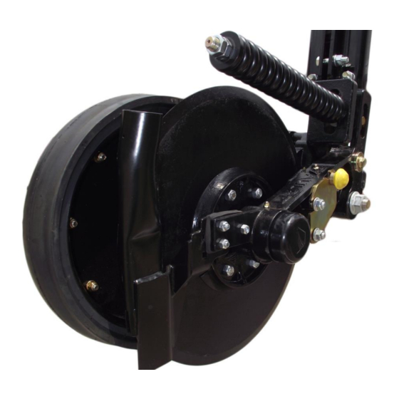
- Page 27 4000-140 & 4000-142 PARTS IDENTIFICATION 4000-140 – 18” COULTER, LESS KNIFE, RH (SHOWN) 4000-142 – 20” COULTER, LESS KNIFE, RH...
- Page 28 4000-140 & 4000-142 PARTS IDENTIFICATION ITEM PART NUMBER DESCRIPTION QUANTITY 2502-155 ¼-20 X 3 ½ HHCS GR 5 ZP 2502-262 3/8-16 X 1 SQ. HCPSS, GR5 ZP 2502-336 5/8-11 X 4 HHCS GR 5 ZP 2505-348 ½-13 X 3 ½ CAR BOLT GR 5 ZP 2506-308 ½-13 X 1 ¼...
- Page 29 4000-141 & 4000-143 PARTS IDENTIFICATION 4000-141 – 18” COULTER, LESS KNIFE, LH (SHOWN) 4000-143 – 20” COULTER, LESS KNIFE, LH...
- Page 30 4000-141 & 4000-143 PARTS IDENTIFICATION ITEM PART NUMBER DESCRIPTION QUANTITY 2502-155 ¼-20 X 3 ½ HHCS GR 5 ZP 2502-262 3/8-16 X 1 SQ. HCPSS, GR5 ZP 2502-336 5/8-11 X 4 HHCS GR 5 ZP 2505-348 ½-13 X 3 ½ CAR BOLT GR 5 ZP 2506-308 ½-13 X 1 ¼...
- Page 31 4000-152 & 4000-153 PARTS IDENTIFICATION ITEM PART NUMBER DESCRIPTION QUANTITY 2502-292 ½ - 13 X 1 HHCS GR 5 YD 2502-503 ¾ - 10 X 2 HHCS GR 5 ZP 1.625” ID X 2.438” OD OIL SEAL 2515-845 1/8 – 27 ZERK 2533-100 2550-027 CONE, LM67048, KOYO...
- Page 32 4000-154 & 4000-155 PARTS IDENTIFICATION ITEM PART NUMBER DESCRIPTION QUANTITY 3/8 – 16 X 1 SERRATED GR 5 ZP 2502-261 1/2 – 13 X 1.5 HHF8 GR 5 ZP 2502-315 2515-842 PROTECTOR CAP HEX SLOTTED NUT 7/8 – 14 UNF 2520-545 2527-569 WASHER...
- Page 33 4000-157 PARTS IDENTIFICATION ITEM PART NUMBER DESCRIPTION QUANTITY 2502-228 M8 X 1.25 X 30 HHFS, CLASS 8.8 2520-207 M8 X 1.25 NYLON FLANGED LOCKNUT, CL 8 TRI-SPOKE 3” X 16” GAUGE WHEEL 2570-786 2965-128 PARTS IDENTIFICATION ITEM PART NUMBER DESCRIPTION QUANTITY 2550-069 SEAL, TRIPLE LIP, NTI # 1812-5...
- Page 34 2966-116-ST & 2966-117-ST ITEM PART NUMBER DESCRIPTION QUANTITY 5/16 – 18 X 1 ¼ CARRIAGE BOLT GR 5 ZP 2505-207 13” WHEEL COVER, BLACK 2515-262 5/16 – 18 FLANGE LOCK NUT 2520-206 D-BOLT, FLANGED, 5/8 – 11 x 2.562 GR 8 2570-766 2965-128 HUB AND BEARING ASSEMBLY, 4 BOLT...
-
Page 35: Troubleshooting
TROUBLESHOOTING Problem Cause Solution Setting coulter Planter not set correctly Ensure that in operation the planter frame is at correct height (20”-22”) and level the toolbar. See page 12 Trash plugging Excessive knife-blade clearance Check and adjust knife-blade clearance. See page 13 Blade not penetrating Insufficient coulter spring pressure Change the rod position or tighten spring. - Page 36 Canada. We’re even getting orders from as far away as Australia and Africa. So, when you buy Yetter products . . .you’re buying a name that’s recognized. A name that’s known and respected. A name that’s become a part of American agriculture and has become synonymous with quality and satisfaction in the field of conservation tillage.
Need help?
Do you have a question about the Nutrient Pro 4000 Series and is the answer not in the manual?
Questions and answers