Advertisement
2967-029B / 2967-029B-PP SHORT U.N.T.
2967-097B SHORT U.N.T.
YETTER MANUFACTURING CO.
Founded 1930
Colchester, IL 62326
Toll Free: (800)447-5777
Fax: (309)776-3222
Website: yetterco.com
E-mail: info@yetterco.com
TM
TITAN
RESIDUE MANAGER
Owner's Manual
Part Identification
2565-696_Rev_O-1 08/2024
SERIES
TM
TM
CNH
Advertisement
Table of Contents

Related Manuals for Yetter TITAN 2967-029B


Summary of Contents for Yetter TITAN 2967-029B
- Page 1 TITAN SERIES 2967-029B / 2967-029B-PP SHORT U.N.T. 2967-097B SHORT U.N.T. RESIDUE MANAGER Owner’s Manual Part Identification 2565-696_Rev_O-1 08/2024 YETTER MANUFACTURING CO. Founded 1930 Colchester, IL 62326 Toll Free: (800)447-5777 Fax: (309)776-3222 Website: yetterco.com E-mail: info@yetterco.com...
-
Page 2: Foreword
It is the user’s responsibility to deliver his machine to the Yetter dealer who sold him the product for service or replacement of defective parts, which are covered by the warranty policy. - Page 3 SAFETY PRECAUTIONS A brief description of signal words that may be used in this manual: DANGER: Indicates an imminently hazardous situation which, if not avoided “will” result in death or serious injury. This signal word is to be limited to the most extreme situations. WARNING: Indicates a potentially hazardous situation which, if not avoided, “could”...
-
Page 4: Table Of Contents
Table of Contents Foreword ............................3 Warranty ............................3 Safety ..............................4 Bolt Torque ............................5 Operation ............................6 Planter Adjustment ......................... 7-8 Installation Instructions ........................ 9-11 Part Identification ........................12-19 Warning: Never work around the toolbar/implement while in a raised position without using safety lockups. -
Page 5: Bolt Torque
BOLT TORQUE NOTICE: Over-tightening hardware can cause just as much damage as under-tightening. Tightening hardware beyond the recommended range can reduce its shock load capacity. All hardware on the Titan Residue Manager is Grade 5 or Grade 8, unless otherwise noted. Grade 5 cap screws are marked with three radial lines on the head. -
Page 6: Operation
OPERATION NOTICE: Where rocks are present, the residue manager should be set to float. The system can be damaged if a rigid setting is used. Adjust the residue manager to move crop residue aside and not to move soil. Adjustments to the residue manager may have to be made with changing field conditions and the type and/or amount of residue. - Page 7 NOTICE: failure to properly set the planter frame height and levelness can result in less than successful operation of the planter and the Yetter product and may result in damaged equipment. All operators should read and thoroughly understand the instructions given prior to using the Yetter product.
-
Page 8: Planter Adjustment
PLANTER ADJUSTMENT... -
Page 9: Installation Instructions
INSTALLATION INSTRUCTIONS Step 1: Attach the 2966-290 mount bracket to the planter unit using (3) ½” bolts and lock nuts. INSERT 1/2” X 1” BOLT THROUGH THE LOWER RIGHT HOLE IN ROW UNIT FROM REAR AND THREAD INTO THE MOUNT BRACKET INSERT 1/2”... - Page 10 INSTALLATION INSTRUCTIONS Step 2: Choose the hole in which to attach the RM wheel assemblies. Attach the RM wheel/hub assemblies to the combo arm using 5/8” lock washers and hex nuts. If applicable, adjust the bearing shield to top dead center then, rotate slightly forward.
-
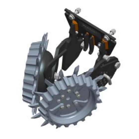
Page 11: Part Identification
PART IDENTIFICATION 2967-029B ITEM PART NO. DESCRIPTION 2502-292 ½-13 X 1 HHCS GRADE 5 2502-294 ½-13 X 1-1/2 HHCS GRADE 5 2502-351 ½-13 X 2 HHCS GRADE 5 2520-357 ½-13 LOCK NUT GRADE A 2520-465 5/8-11 FLANGE NUT GRADE 8 2525-352 ½... - Page 12 2502-391 5/8-11 X 2 HHCS GRADE 5 2520-357 ½-13 LOCK NUT GRADE A 2520-459 5/8-11 LOCK NUT GRADE B 2526-453 5/8 SAE FLAT WASHER 2565-162 YETTER DECAL 2570-448 BOW TIE COTTER PIN 2966-290 MOUNT BRACKET 2966-292 2967-622 9/16 SPACER 2967-639...
- Page 13 PARTS IDENTIFICATION 2967-029B-BW-PP ITEM PART NO. DESCRIPTION 2502-292 ½-13 X 1 HHCS GRADE 5 2502-294 ½-13 X 1-1/2 HHCS GRADE 5 2502-351 ½-13 X 2 HHCS GRADE 5 2520-357 ½-13 LOCK NUT GRADE A 2520-465 5/8-11 FLANGE NUT GRADE 8 2525-352 ½...
- Page 14 5/8-11 X 2 HHCS GRADE 5 2520-357 ½-13 LOCK NUT GRADE A 2520-459 5/8-11 LOCK NUT GRADE B 2526-453 5/8 SAE FLAT WASHER 2565-162 YETTER DECAL 2570-448 BOW TIE COTTER PIN 2966-2002 MOUNT BRACKET PP 2966-292 2967-622 9/16 SPACER 2967-639...
- Page 15 PARTS IDENTIFICATION 2967-097B-ST ITEM PART NO. DESCRIPTION 2502-244 3/8-16 X 1-1/4 HHCS GRADE 5 2502-293 ½-13 X 1-1/4 HHCS GRADE 5 2502-316 ½-13 X 3-1/2 HHCS GRADE 5 2505-339 ½-13 x 1-1/2 CARRIAGE BOLT GRADE 5 2520-255 3/8-16 LOCK NUT GRADE A 2520-357 ½-13 LOCK NUT GRADE A 2520-361...
- Page 16 PARTS IDENTIFICATION 2965-135 UP-STOP KIT ITEM PART # DESCRIPTION 2502-244 3/8-16 x 1-1/4 HHCS GR 5 2960-223 UP-STOP 2520-255 3/8-16 HEX LOCK NUT 2526-253 3/8 SAE FLATWASHER...
- Page 17 PARTS IDENTIFICATION 2966-140-ST-FW 2966-140-ST-PFW RIGHT HAND SHARK TOOTH WHEEL ASSEMBLY 2966-140-BW-FW RIGHT HAND BEVEL WHEEL ASSEMBLY...
- Page 18 PARTS IDENTIFICATION 2966-140-STF-PFW RIGHT HAND SHARKTOOTH FINGER WHEEL ASSEMBLY...
- Page 19 ITEM PART NO DESCRIPTION 2505-207 5/16-18 X 1-1/4 CARRIAGE HEAD BOLT GRADE 5 2520-206 5/16-18 FLANGE LOCK NUT 2570-740 D-BOLT FLANGE HEAD 5/8-11 X 2.812 GRADE 8 2965-128 HUB/BEARING ASSEMBLY 2550-069 SEAL 2570-594 BEARING 2570-715 INSERT 2965-351 2533-110 GREASE FITTING 2965-352 HUB CAP 2967-602...
- Page 20 2565-696_REV_O-1 06/2024...
Need help?
Do you have a question about the TITAN 2967-029B and is the answer not in the manual?
Questions and answers