Table of Contents
Advertisement
Quick Links
Advertisement
Table of Contents

Subscribe to Our Youtube Channel
Related Manuals for Yetter MAVERICK HR PLUS 2984 Series


Summary of Contents for Yetter MAVERICK HR PLUS 2984 Series
- Page 1 2984 Series MAVERICK™ ™ ™ ™ HR PLUS OPERATOR & PARTS MANUAL 2565-762_REV_L • 12/2018 YETTER MANUFACTURING CO. FOUNDED 1930 COLCHESTER, IL 62326-0358 TOLL FREE: 800/447-5777 309/776-3222 (FAX) WEBSITE: WWW.YETTERCO.COM E-MAIL: INFO@YETTERCO.COM...
-
Page 2: Table Of Contents
TABLE OF CONTENTS FOREWORD…………………………………………………………3 WARRANTY………………………………………………………….3 SAFETY………………………………………………………………4 BOLT TORQUE……………………………………………………..5 ASSEMBLY INSTRUCTIONS………………………………….6-17 OPERATION……………………………………………………18-22 MAINTENANCE………………………………………………..23-30 PARTS IDENTIFICATION…………………………………….31-56 TROUBLESHOOTING………………………………………...58-59... -
Page 3: Foreword
Important will WARRANTY Yetter Manufacturing warrants all products manufactured and sold by it against defects in material. This warranty being expressly limited to replacement at the factory of such parts or products as shall appear to be defective after inspection. -
Page 4: Safety
SAFETY A brief description of signal words that may be used in this manual: CAUTION: Used as a general reminder of good safety practices or to direct attention to unsafe practices. WARNING: Denotes a specific potential hazard DANGER: Denotes the most serious specific potential hazard. SAFETY PRECAUTIONS You can make your farm a safer place to live and work if you observe the safety precautions given. -
Page 5: Bolt Torque
BOLT TORQUE Note: Right hand and left hand designations are based on sitting in the tractor and facing forward. READ THESE INSTRUCTIONS FIRST: 1. Improperly tightened bolts will result in damage, breakage, expense, and down time. 2. Always replace bolts with the specified grade and type. 3. -
Page 6: Assembly Instructions
ASSEMBLY INSTRUCTIONS 2984 MAVERICK OPENER ™ STEP 1. Mark the location of the center of each row on the toolbar. Then measure from row 4” and place a mark on the rear side of toolbar. This mark will give a reference point to where the edge of the clamp bracket (3000-409) should be located so that the fertilizer knife will be centered directly on the row. - Page 7 ASSEMBLY INSTRUCTIONS STEP 3. Attach the fertilizer knife to the 2984 knife mount using 2) ½” x 2” GRADE. 8 bolts and lock nuts. (Rock Trip model use 3) ½” x 2” GRADE 8) STEP 4. Tighten all bolts to recommended torques from the table of this manual, unless the torque is otherwise specified.
- Page 8 ASSEMBLY INSTRUCTIONS 2984-028-ST - RESIDUE MANAGER 2984-029-ND - RESIDUE MANAGER STEP 1. Install the wheel stem assembly Initial Adjustment for the residue manager needs to be set at soil surface. For example: fertilizer is to be placed 6” deep, the residue manager should be adjusted 6” above the tip of the knife. Field adjustment: In field adjustments to the residue manager will need to be done for best performance of residue manager.
- Page 9 ASSEMBLY INSTRUCTIONS 2984-030-N – NOTCHED DISC SEALER KIT 2984-030-S – SMOOTH DISC SEALER KIT STEP 1.
- Page 10 ASSEMBLY INSTRUCTIONS 2984-030-N – NOTCHED DISC SEALER KIT 2984-030-S – SMOOTH DISC SEALER KIT STEP 2:...
- Page 11 ASSEMBLY INSTRUCTIONS 2984-030-N – NOTCHED DISC SEALER KIT 2984-030-S – SMOOTH DISC SEALER KIT STEP 3. Attach the blade/hub assembly to the 2920-329 L-bracket using the D-bolt through a 5/8” lock washer and 5/8” hex nut. Torque 150 ft.lbs.
- Page 12 ASSEMBLY INSTRUCTIONS 2984-030-N – NOTCHED DISC SEALER KIT 2984-030-S – SMOOTH DISC SEALER KIT STEP 4. Adjust the angle of the disc blades so that the blades are approximately 8” apart and 4” from the center of the knife. TRAVEL STEP 5.
- Page 13 ASSEMBLY INSTRUCTIONS ROLLING BASKET ATTACHMENT STEP 1. Attach Rolling Basket mount bracket to the Maverick ™ Opener using the 5/8” X 6 ½” hex bolts, secure with 5/8” lock hex nuts.
- Page 14 ASSEMBLY INSTRUCTIONS ROLLING BASKET ATTACHMENT STEP 2. Attach the pivot bracket and bushing (apply “never seize” lubrication to the bushing before installing) to the mount bracket using the 5/8” x 6 ½” hex bolt and 5/8” lock hex nut.
- Page 15 ASSEMBLY INSTRUCTIONS ROLLING BASKET ATTACHMENT STEP 3. Install the basket with flange mount bearings to the basket mount bracket using (4) 7/16” x 1 ½” hex bolt and 7/16” lock hex nut.
- Page 16 ASSEMBLY INSTRUCTIONS ROLLING BASKET ATTACHMENT STEP 4. Center the basket in the basket mount bracket and “triple tighten” the set screws.
- Page 17 ASSEMBLY INSTRUCTIONS ROLLING BASKET ATTACHMENT STEP 5. Attach the basket mount bracket to the pivot bracket using the 5/8” x 4 ½” hex bolt and 5/8” lock hex nut. Also, install the adjustment pin and 1/8” hairpin cotter.
-
Page 18: Operation
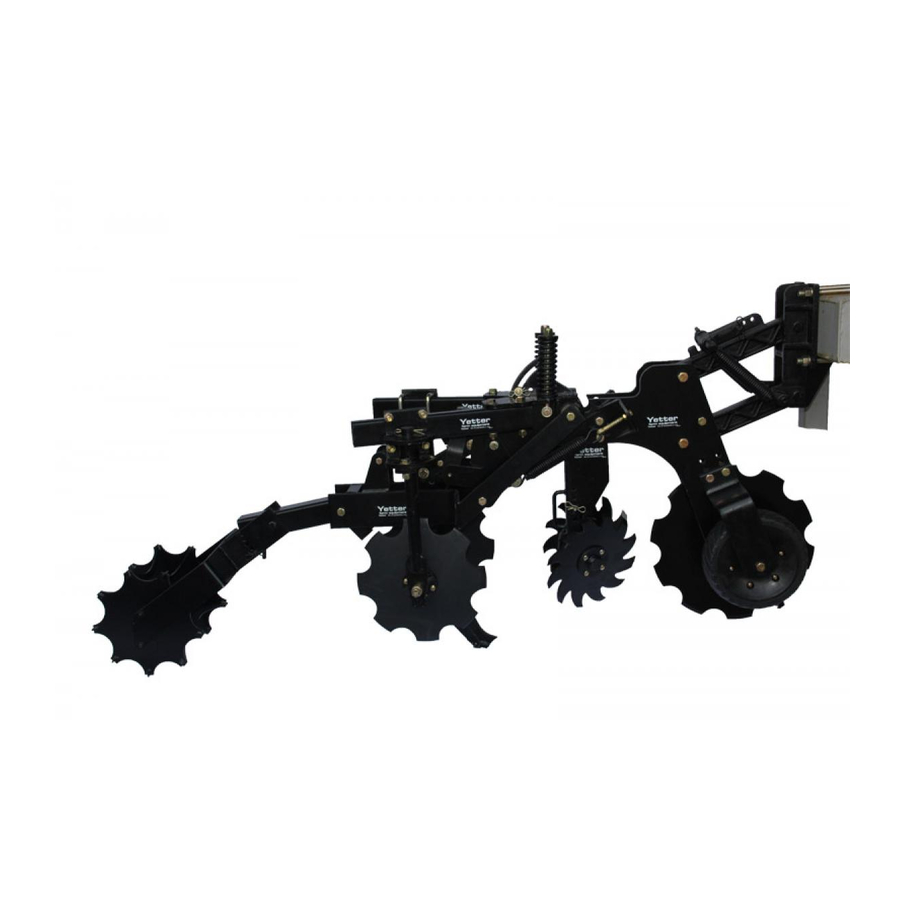
OPERATION YETTER model 2984 MAVERICK OPENER is a multi-functional tool designed for use in a fertilizer management system. It is capable of residue management, precision fertilizer placement, soil tilth, and soil berm/mound building all in one pass. Thus creating a seedbed that will increase your Return On Investment. - Page 19 OPERATION WARNING Never clean, lubricate or adjust a machine that is in motion. Always lower or block the implement before performing service. If machine must be serviced in the raised position, jack or block it up to prevent it from accidentally falling and injuring someone.
- Page 20 OPERATION STEP 1. Disengage Rolling Basket Attachment – Lift basket and insert pin. See diagram.
- Page 21 OPERATION STEP 2. Set the coulter depth based on soil conditions, (i.e. tilth, stones or crop residue). For proper operation of the MAVERICK OPENER , the coulter must cut through crop residues including roots. For best performance 3”-4” depth is recommended. Raising the blade helps to cut residue rather than pushing it ahead and not cutting.
- Page 22 OPERATION – ADJUSTMENT...
-
Page 23: Maintenance
MAINTENANCE LUBRICATION: USE #2 MULTI-PURPOSE POLYUREA GREASE To ensure longevity and reliability of the MAVERICK OPENER HR Plus, the recommended lubrication schedule should be followed using multi-purpose grease at intervals as indicated. BEARING ADJUSTMENT: 1. Raise the toolbar until the blade is clear of the ground. Place a safety stand under the toolbar. Remove the cotter pin, slotted nut, washer and bolt from the hub assembly. - Page 24 MAINTENANCE BEARING ASSEMBLY AND LUBRICATION Practice Safety Understand and practice safe service procedures before doing work. Follow ALL the operating, maintenance and safety information in the equipment operator manual. Clear the area of bystanders, especially small children, when performing any maintenance or adjustments.
- Page 25 MAINTENANCE NOTE: Be certain to align the grease fitting with the slot in the wheel and the hubcap so that the grease can flow freely.
- Page 26 MAINTENANCE Grease must fill this Hubcap cavity.
- Page 27 Alternative Lubricants Conditions in certain geographical areas may require special lubricants and lubrication practices which do not appear in the operator's manual. If there are any questions, consult Yetter Manufacturing Co. to obtain latest information and recommendation. DESCRIPTION OUNCES OF GREASE...
- Page 28 MAINTENANCE Lubrication Symbols Lubricate with grease at hourly interval indicated on symbol. Lubrication Intervals LUBRICATION: Use Polyurea NLGI grade #2 IMPORTANT: The recommended service intervals are based on normal conditions; severe or unusual conditions may require more frequent lubrication. Perform each lubrication and service procedure at the beginning and end of each season. Clean grease fittings before using grease gun, to avoid injecting dirt and grit into the bearing.
- Page 29 MAINTENANCE • Always lubricate the implement thoroughly before taking it to the field. • Always lower the implement until all shank points rest on the ground. • Lubricate fittings and bushings as indicated in the diagram below. • Be sure grease fittings are free from dirt and paint so the lubricant is certain to enter the proper areas.
- Page 30 • Clean machine thoroughly to remove all dirt, debris and crop residue, which would hold moisture and cause rusting. • Inspect machine for worn or broken parts. See your Yetter Farm Equipment dealer during the off-season so that parts or service can be acquired when machine is not needed in the field.
-
Page 31: Parts Identification
PARTS IDENTIFICATION 3000-131 PLATE ASSEMBLY... - Page 32 PARTS IDENTIFICATION...
- Page 33 PARTS IDENTIFICATION 2984-029-ND-R (SHOWN) 2984-029-ND-L...
- Page 34 PARTS IDENTIFICATION...
- Page 35 PARTS IDENTIFICATION 2984-028-ST...
- Page 36 PARTS IDENTIFICATION 2984-030-N...
- Page 37 PARTS IDENTIFICATION...
- Page 38 PARTS IDENTIFICATION 2984-030-S...
- Page 39 PARTS IDENTIFICATION...
- Page 40 PARTS IDENTIFICATION MANUFACTURED 01/2011 – 07/2017...
- Page 41 PARTS IDENTIFICATION MANUFACTURED 01/2011 – 07/2017...
- Page 42 PARTS IDENTIFICATION 2984-123-N-RT STRIP TILL ASSY, NOTCHED BLADE, ROCK TRIP MANUFACTURED 01/2011 – 07/2017...
- Page 43 PARTS IDENTIFICATION 2984-123-N-RT MANUFACTURED 01/2011 – 07/2017...
- Page 44 PARTS IDENTIFICATION MANUFACTURED 08/2017 – PRESENT...
- Page 45 PARTS IDENTIFICATION MANUFACTURED 08/2017 – PRESENT...
- Page 46 PARTS IDENTIFICATION MANUFACTURED 08/2017 – PRESENT...
- Page 47 PARTS IDENTIFICATION MANUFACTURED 08/2017 – PRESENT...
- Page 48 PARTS IDENTIFICATION 2984-140 MANUFACTURED 08/2017 – PRESENT...
- Page 49 PARTS IDENTIFICATION 2984-152 MANUFACTURED 08/2017 – PRESENT...
- Page 50 PARTS IDENTIFICATION...
- Page 51 PARTS IDENTIFICATION...
- Page 52 PARTS IDENTIFICATION...
- Page 53 PARTS IDENTIFICATION 2984-141...
- Page 54 PARTS IDENTIFICATION...
- Page 55 PARTS IDENTIFICATION 2984-107...
- Page 56 PARTS IDENTIFICATION...
- Page 57 NOTES:...
-
Page 58: Troubleshooting
TROUBLESHOOTING PROBLEM CAUSE SOLUTION Poor overall performance Toolbar not adjusted correctly Adjust the toolbar so that during operation it is level and at a height of 24” from the bottom of the toolbar to the soil surface. Unit is not set correctly See Operations section for proper adjustments Toolbar height too high... - Page 59 TROUBLESHOOTING PROBLEM POSSIBLE CAUSE SOLUTION Berm size or shape Disc sealer blades not at Adjust blades to Is not uniform equal angle exact same angle Insufficient spring pressure Change spring On rolling basket attachment to increase Down pressure (See adjustments) Large clods or chunks Insufficient sprint pressure Change spring...
- Page 60 East, the South, the West and now north into Canada. We’re even getting orders from as far away as Australia and Africa. So, when you buy Yetter products . . .you’re buying a name that’s recognized. A name that’s known and respected. A name that’s become a part of American agriculture and has become synonymous with quality and satisfaction in the field of conservation tillage.
Need help?
Do you have a question about the MAVERICK HR PLUS 2984 Series and is the answer not in the manual?
Questions and answers