Table of Contents
Advertisement
Advertisement
Chapters
Table of Contents

Related Manuals for Tektronix 2245A


Summary of Contents for Tektronix 2245A
- Page 1 O P E R A TO R S 0 7 0 -6 5 5 8 -0 1 M A N U A L Product Group 46 2245A PORTABLE OSCILLOSCOPE OPERATORS Please Check for CHANGE INFORMATION at the Rear of This Manual...
- Page 2 Copyright © 1987,1889 Tektronix, Inc. All rights reserved. Contents of this publication may not be reproduced in any form without the written permis sion of Tektronix, Inc. Products of Tektronix, Inc. and its subsidiaries are covered by U.S. and foreign patents and/or pending patents. TEKTRONIX, TEK, SCOPE-MOBILE and are registered trademarks of Tektronix, Inc.
- Page 3 Certificate of the Manufacturer/lmporter We hereby certify that th e ________________________________________ _________ 2245A OSCILLOSCOPE AND ALL INSTALLED OPTIONS_________ complies with the RF Interference Suppression requirements of Amtsbl.-Vfg 1046/1984. The German Postal Service was notified that the equipment is being marketed.
- Page 4 NOTICE to the user/operator: The German Postal Service requires that Systems assembled by the operator/user of this instrument must also comply with Postal Regulation, Vfg. 1046/1984, Par. 2, Sect. 1. HINWEIS fur den Benutzer/Betreiber: Die vom Betreiber zusammengestellte Anlage, innerhalb derer dies Gerat eingesetzt wird, mu/3 ebenfalls den Voraussetzungen nach Par.
-
Page 5: Table Of Contents
Crt, Power, and Display ................2-1 Vertical ...................... 2-3 Horizontal ....................2-7 T rig g e r...................... 2-11 A Trigger Modes ................2-13 B Trigger Modes ................2-14 Rear Panel....................2-17 Measurements and Auto Setup Controls ..........2-18 2245A Operators... - Page 6 Initial Setup ....................4-1 Auto Setup Function ................4-2 Trace Rotation Adjustm ent.................4-3 Probe Low-Frequency Compensation............. 4-3 Vertical Deflection Check ................4-5 Timing Checks ..................4-6 SECTION 5—BASIC APPLICATIONS Introduction....................5-1 Voltage Measurement Cursors ............... 5-1 Voltage Difference ................5-1 2245A Operators...
- Page 7 CH 1 to CH 4 Signal Delay M a tch ............ 7-19 CH 3 to CH 4 Signal Delay M a tch ............ 7-20 Ch 1 and CH 2 Vertical Bandwidth ..........7-21 CH 3 and CH 4 Vertical Bandwidth........... 7-22 2245A Operators...
- Page 8 AUTO SETUP FUNCTIONS ..............7-48 Check External Z-Axis Input ............7-48 PROBE ADJUST O u tp u t..............7-49 AUTO SETUP Functional Check ............7-49 OPTION 15 ....................7-50 Signal Output ..................7-50 A GATE O u tp u t.................. 7-51 2245A Operators...
- Page 9 Standard A ccessories................8-1 Optional Accessories................8-2 Instrument Enhancements ..............8-2 Transportation A id s ................8-2 C am eras....................8-2 Probes....................8-3 Viewing Hoods ..................8-3 APPENDIX A - AUTO-SETUP/MIN SETUP Control Settings APPENDIX B - FACTORY SETTINGS CHANGE INFORMATION 2245A Operators...
-
Page 10: List Of Illustrations
LIST OF ILLUSTRATIONS Figure Page The 2245A O scilloscope............... 1-1 2 Optional power cords ..............1-5 1 CRT, power, and display controls ..........2-2 CH 1 and CH 2 vertical controls and connectors...... 2-4 Vertical connectors and CH 3 and CH 4 controls and Indicators.............. - Page 11 1 Test Equipment Required............. 7-3 Slgnal-to-Graticule Accuracy ........... 7-16 Settings for Timing Accuracy Checks ........7-40 Delay Time Accuracy ..............7-43 AUTO-SETUP Control S ettings............. A-1 MIN SETUP Control S e ttin g s............A-4 Factory Settings ................B-1 2245A Operators...
-
Page 12: Operators Safety Summary
Symbols in this Manual This symbol Indicates where applicable cautionary or other information is to be found. For maximum input voltage see Table 6-1. Symbols as Marked on Equipment DANGER—High voltage. Protective ground (earth) terminal. ATTENTION—Refer to manual. 2245A Operators vili... - Page 13 To avoid fire hazard, use only a fuse of the correct type, voltage rating and current rating as specified on the back of your product and in Table 6-1. Do Not Operate in an Explosive Atmosphere To avoid explosion, do not operate this product in an explosive atmosphere. 2245A Operators...
- Page 14 Do Not Remove Covers or Panels To avoid personal injury, do not remove the product covers or panels. Do not operate the product without the covers and panels properly installed. 2245A Operators...
- Page 15 Q service This D o cu m e n t is a co m p lete scan fro m the O rig in al T e ktro n ix M anual Q service...
- Page 16 This Document is a complete Scan from the original Tektronix manual For enquiries about our complete High quality line of technical Manuals in PDF mailto : Qservice@otenet.gr OTHER --------------------------------- ' > SIDE...
-
Page 17: Section 1-Introduction
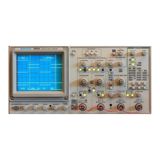
Introduction PRODUCT OVERVIEW Description The 2245A is a 100 MHz, four-channel, dual-sweep, portable oscilloscope for general-purpose use (Figure 1-1), A microprocessor-based operating system controls most of the functions in the instrument, Including a voltage and time cursor measurement system and a single-button automatic front-panel setup feature. - Page 18 ALT and B Horizontal Modes. By pressing a single button (AUTO SETUP), the front-panel controls can be set up to produce a usable waveform display based on the voltage and time characteristics of the input signals. 2245A Operators...
-
Page 19: Standard Accessories
Introduction Standard Accessories The following items are standard accessories shipped with the 2245A instrument: 2 Probes, 10X, 1.5 meter, with accessories 1 Power cord 1 Power cord clamp 1 Operators manual 1 Reference guide 1 Crt filter, blue plastic (installed) -
Page 20: Preparation For Use
Install the proper fuse and reinstall the fuse-holder cap. Line Voltage and Power Cord The 2245A operates on line voltages from 90 to 250 V with line frequencies ranging from 48 to 440 Hz. No line voltage selecting is necessary. Instru... - Page 21 CEE — International Com mission on Rules for the Approval of Electrical Equipm ent IEC — International Electrotechnical Commission N E M A — National Electrical M anufacturer's Association S E V — Schw eizevischer Elektrotechischer Verein 2931 6558-02 Figure 1-2. Optional power cords. 2245A Operators...
-
Page 22: Instrument Cooling
VERTICAL MODE buttons (CH 1 and CHOP/ALT). Press the ADD button (down-arrow) to underline SELF CAL MEASUREMENTS. Press the CH 2 button (RUN) to start the routine, then CH 4 (CUIT) or CLEAR MEAS'MT button to return to the normal oscilloscope mode. 1 -6 2245A Operators... -
Page 23: Repackaging For Shipment
Seal the shipping carton with an industrial stapler or strapping tape. Mark the address of the Tektronix Service Center and your own return address on the shipping carton. 2245A Operators... - Page 24 This Document is a complete Scan from the original Tektronix manual For enquiries about our complete High quality line of technical Manuals in PDF mailto : Qservice@otenet.gr OTHER --------------------------------- ' > SIDE...
- Page 25 Q service This D o cu m en t is a co m p lete scan fro m the O rig in al T e ktro n ix M anual Q service > < 0 rv>...
- Page 26 This Document is a complete Scan from the original Tektronix manual For enquiries about our complete High quality line of technical Manuals in PDF mailto : Qservice@otenet.gr OTHER --------------------------------- ' > SIDE...
-
Page 27: Section 2-Controls, Connectors, And Indicators
( © BEAM FIND B u tto n —Locates off-screen and overscanned displays when the button is held in. Limits the vertical and horizontal deflection within the display area and unblanks the crt. 2245A Operators... - Page 28 Internal graticule lines provide parallax-free viewing of trace and graticule lines. 0%, 10%, 90% and 100% points marked at the left edge of the graticule aid in making rise- and fall-time measurements. 2 -2 2245A Operators...
-
Page 29: Vertical
In ADD mode when AUTO LEVEL TRIGGER MODE or CHOP VERTICAL MODE is selected, the algebraic sum of Channel 1 and Channel 2 display provides the internal signal source for the trigger system when the trigger source is VERT. 2245A Opetators... - Page 30 5 V per division in a 1-2-5 sequence of 11 steps. The switches are detented, continuous-rotation controls with no end stops. The VOLTS/DIV readouts reflect attenuation factors of coded attenuator probes connected to the vertical inputs. 2245A Operators...
- Page 31 1 Hz or less using a compensated 10X probe. With AC Coupling selected, an AC symbol ( A; ) Is displayed to the right of the associated VOLTS/DIV readout. An ac symbol is also displayed after the value readout of a CURSOR VOLTS measurement. 2245A Operators...
- Page 32 (at about 1 kHz into a 1 M fl load) for compensating voltage probes and checking the vertical deflection accuracy. Figure 2-3. V e rtical connectors and CH 3 and CH 4 co ntrols and ind icato rs. 2245A Operators...
-
Page 33: Horizontal
No action occurs in X-Y mode. When X10 MAG is on, a X10 symbol is displayed next to the SEC/DIV readouts. The readouts reflect correct display sweep speeds for the X I0 MAG displays and the unmagnified displays. 2245A Operators... -
Page 34: Behavior For Horizontal Mode Changes
Controls, Connectors, and Indicators Figure 2-4. Horizontal controls and indicators. MODE Buttons (Up-Arrow and Down-Arrow) and Indica tors—Select the operating mode of the horizontal deflection system. Pressing the Up-/Down-Arrow buttons selects the horizontal deflec tion mode as shown by the MODE lights. Not all Measurement modes are compatible with all horizontal deflection modes. - Page 35 Calibrated sweep speeds are obtained with the A and B SEC/DIV VAR control in the detent (fully clockwise) position. The A SEC/DIV switch setting is set only from the A Horizontal MODE and the B SEC/DIV switch is set only from the ALT or B Horizontal MODE. 2245A Operators...
- Page 36 11th vertical graticule lines. k- OR DELAY—This control has the following functions: 1. Positions the reference and delta cursors together in the CURSOR VOLTS, 1/TIME, or TIME measurement mode when the Horizontal MODE is A (also X-Y for CURSOR VOLTS). 2-10 2245A Operators...
-
Page 37: Trigger
B to X-Y Horizontal MODE. ) SLOPE B u tto n —Selects the slope (positive- or negative-going) of the trigger source signal that triggers either the A sweep or the B sweep. (Button lit = positive-going; button not lit = negative-going.) 2-11 2245A Operators... - Page 38 A or B sweep is triggered. Adjusting the LEVEL control to either end of its range, in the AUTO LEVEL trigger mode, resets the limits of the Trigger LEVEL control range to the peak-to-peak amplitude of the trigger source signal. 2-12 2245A Operators...
-
Page 39: A Trigger Modes
TRIGGER LEVEL control is adjusted to a new level setting. NORM —Triggers the A sweep when the A Trigger LEVEL control is set within the peak-to-peak limits of an adequate trigger signal. When the A sweep is not triggered, no baseline trace is displayed. 2245A Operators 2-13... -
Page 40: B Trigger Modes
10 Hz. Switch to NORM triggering if the repetition rate is too slow for auto leveling. The A Sweep must be running (free-running or triggered) for B Sweep to trigger. 2-14 2245A Operators... - Page 41 CH 2—The signal applied to the CH 2 input connector is the source of the trigger signal. CH 3—The signal applied to the CH 3 input connector is the source of the trigger signal. 2-15 2245A Operators...
-
Page 42: Vert Trigger Source
NOISE REJ (Noise R eject)—Couples all frequency components of the input signal to the trigger circuitry but increases the peak-to-peak signal amplitude required to produce a trigger event. 2-16 2245A Operators... -
Page 43: Rear Panel
1.8 V. Z-Axis voltage above the threshold voltage decreases the intensity, and 3.8 V or more produces noticeable modulation. The Z-Axis signals must be time-related to the displayed signal to obtain a fixed intensity-modulated crt display. ) Fuse H older—Contains the primary power fuse. 2-17 2245A Operators... -
Page 44: Measurements And Auto Setup Controls
Measurements and Auto Setup Controls Refer to Figure 2-7 for location of items 42 through 46. (42) CLEAR M E A S ’ MT—Clears displayed service menus and cursor measurements functions. 2-18 2245A Operators... - Page 45 (45) TIME —Turns on the delta-time measurement mode and displays two positionable vertical cursors in A MODE. ALT and B MODE displays have two B sweeps, and in ALT MODE the A sweep has two intensi- 2-19 2245A Operators...
- Page 46 Setups are based on the characteristics of the applied signals. The voltage and frequency characteristics of the input signal must be within the limits of the 2245A specifications. Auto-setup action for each front-panel control is shown in Appendix A. NOTE MIN SETUP as described below is only available on instru...
- Page 47 Q service This D o cu m e n t is a co m p lete scan fro m the O rig in al T e ktro n ix M anual Q service > > > > — i...
- Page 48 This Document is a complete Scan from the original Tektronix manual For enquiries about our complete High quality line of technical Manuals in PDF mailto : Qservice@otenet.gr OTHER --------------------------------- ' > SIDE...
-
Page 49: Section 3-Operators Familiarization
0.2 division minor graticule markings on the center graticule lines. Also position one of the measurement points of the waveform as pre cisely as possible on one of the major graticule marks to be used as a measurement reference point. 2245A Operators... - Page 50 * — X10 C O U PLIN G -1 '-COUPLING “ -S E C /D IV UNCAL VOLTS/DIV— 1 INPUT COUPLING SYMBOLS A C = ~ DC = • - GND = 6558-10 Figure 3-1. Readout display locations. 2245A Operators...
-
Page 51: Connecting Input Signals
Connecting Input Signals G ro u n d in g The most reliable signal measurements are made when the 2245A and the unit under test are connected by a common reference (ground lead) in addition to the single lead or probe. The ground lead of the probe provides the best grounding method for signal interconnection and ensures the maxi... -
Page 52: Probes
Use suitable impedance-matching devices. E xternal T rig g e rin g Any of the four vertical channels in the 2245A can be used as a source of A and B trigger signals. When you need a trigger signal source different from the one derived from displayed signals, you can use any free vertical input channel. -
Page 53: Auto Setup
The waveform is horizontally centered and vertically positioned within the crt display. The voltage and frequency characteristics of the input sig nal must be within the limits of the 2245A specifications given in Section 6. Auto-setup action for each front-panel control is shown in Appendix A. -
Page 54: Time Measurements
Horizontal MODE or the B delayed waveforms in either ALT or B Horizontal MODE. The |<- OR DELAY control positions both cursors or delay times (reference and delta) together, and the -»( control positions the independ ent delta cursor or delay when TIME or 1/TIME measurements are se lected. 2245A Operators... -
Page 55: Behavior For Horizontal Mode Changes
See Table 3-1 for compatible and Incompatible modes. Table 3-1 Behavior for Horizontal MODE Changes Measurement Compatible Incompatible Mode Horizontal Horizontal Modes Modes CURSOR VOLTS A, X-Y ALT, B TIME and 1/TIME A, ALT, B 2245A Operators... -
Page 56: Measurement Compatibility And Error Messages
Configure Menu in the “ SERVICE MENU FEATURES" part of this section.) The displayed readout is the value of the measurement at the instant it is displayed. B Trigger AUTO LEVEL acquisitions do not occur when the A Trigger MODE is SGL SEQ. 2245A Operators... -
Page 57: Service Menu Features
Select Quit (CH 4 button) to exit the SERVICE MENU and return to the normal oscilloscope operation. SERVICE MENU/ DIAGNOSE T MENU (CH 1) CONFIGURE (ADD) SELF CAL MEASUREMENTS INTERNAL SETTINGS MENU/ EXERCISER MENU/ QUIT (CH 4) 6558-12 Figure 3-3. Service Menu. 2245A Operators... -
Page 58: Configure Menu
Selecting YES will cause the trigger slopes to preset to “ +” when TV trig mode is selected, and the configure menu is exited. If NO is selected, the scope will not use a preset slope when a TV trig mode is selected. 3-10 2245A Operators... -
Page 59: Self Cal Measurements
The SELF CAL MEASUREMENTS routine stores calibration constants that set the accuracy of the internal measurement system. NOTE SELF CAL MEASUREMENTS can be performed anytime af ter a 20-minute warmup time to ensure the accuracy stated in Section 6. 2245A Operators 3-11... -
Page 60: Internal Settings Menu
INTERNAL SETTINGS MENU/ MAKE FACTORY SETTINGS T MENU- (CH 1) ADJUST VERTICAL OUTPUT (ADD) QUIT- (CH 4) 6558-14 Figure 3-5. Internal Settings Menu. MAKE FACTORY SETTINGS. Sets the front-panel controls and menu con figurations as described in Appendix B. 3-12 2245A Operators... - Page 61 Q service This D o cu m e n t is a co m p lete scan fro m the O rig in al T e ktro n ix M anual Q service >...
- Page 62 This Document is a complete Scan from the original Tektronix manual For enquiries about our complete High quality line of technical Manuals in PDF mailto : Qservice@otenet.gr OTHER --------------------------------- ' > SIDE...
-
Page 63: Section 4-Operator Checks And Adjustments
1. Press in the POWER switch button (ON) and let the instrument warm up (20 minutes is recommended for maximum accuracy). 2. Set the Instrument front-panel controls to obtain a baseline trace: Vertical Controls VERTICAL MODE CH 1 POSITION Center the trace VOLTS/DIV VOLTS/DIV VAR Calibrated detent Channel 1 COUPLING 2245A Operators... -
Page 64: Auto Setup Function
1. Connect signal(s) displayed appropriate input connector(s). For triggering to be set up properly when the AUTO SETUP button is pressed, connect the trigger-source signal to the lowest numbered channel that will be turned on. 2245A Operators... -
Page 65: Trace Rotation Adjustment
The attenuator probes are equipped with compensation adjustments. To ensure the best measurement accuracy, always check probe compen sation before making measurements. 1. Connect the two supplied 10X probes to the CH 1 and CH 2 BNC input connectors. 2245A Operators... - Page 66 PROBE ADJUST square-wave signal. 9. Repeat Step 6 for the second probe on the CH 2 BNC input connector. NOTE Refer to the instruction manual supplied with the probe for more detailed information about the probes and adjustment procedure. 2245A Operators...
-
Page 67: Vertical Deflection Check
2. Connect both probe hook tips to the PROBE ADJUST connector. 3. Set: VERTICAL MODE CH 1 Horizontal MODE 4. Press AUTO SETUP button. 5. Set CH 1 and CH 2 VOLTS/DIV switches to 0.1 V for the attached 10X probes. 2245A Operators... -
Page 68: Timing Checks
|<- OR DELAY control (both cursors are positioned together). 4. Adjust the -H control for a reading of 800.0 p.s 5. Check that the cursors are eight divisions apart. 6. Press the CLEAR MEAS’ MT button to remove the cursors from the display. 2245A Operators... - Page 69 Q service This D o cu m e n t is a co m p lete scan fro m the O rig in al T e ktro n ix M anual Q service > "O "O El 03 > > C />...
- Page 70 This Document is a complete Scan from the original Tektronix manual For enquiries about our complete High quality line of technical Manuals in PDF mailto : Qservice@otenet.gr OTHER --------------------------------- ' > SIDE...
-
Page 71: Section 5-Basic Applications
Basic Applications Introduction The TEKTRONIX 2245A Oscilloscope has a cursor measurement system for making accurate, direct-readout voltage, time, and frequency measurements. The measurements given in this section are examples of typical applications using this measurement system. After becoming familiar with the controls, indicators, and capabilities of the instrument, you can develop convenient methods for making special measurements for your own applications. - Page 72 Noise and other signals riding on the sig nal to be measured will cause a slight displacement of the cursors from the displayed waveform peaks, and above 50 MHz the bandwidth rolloff of the trigger circuit will affect the initial cursor positions on the waveform. 2245A Operators...
-
Page 73: Time Measurement Cursors
|«- OR DELAY control positions both cursors together, and the -H control positions the independent (delta-time) cursor. 1. Apply the signal to the input connector(s). NOTE Make sure that the signal used as the trigger source is con nected to the lowest numbered channel that will be turned 2245A Operators... -
Page 74: Period M Easurem Ent
This is a time-difference measurement. Position the TIME cursors to define a full period (1 cycle) of the input waveform. Its value is displayed. Use the setup for making time-difference measurements as a guideline for making period measurements (see Figure 5-2). 2245A Operators... -
Page 75: Frequency Measurement
Basic Applications Frequ en cy M ea su re m en t A frequency measurement is made using the same method as a period measurement; the difference is that the 1/TIME measurement mode is selected instead of TIME. The measurement value is displayed in frequency units. -
Page 76: Rise-Time Measurements
Use the following steps as a guideline In making rise-time measurements. 1. Apply the signal to the CH 1 input connector. 2. Set: Vertical MODE CH 1 Horizontal MODE A Trigger SLOPE 2245A Operators... - Page 77 10% reference graticule line. Then use the -») control to align the second cursor to the point where the rising edge crosses the 90% graticule line and read the rise time displayed in the top line of the crt readout (see Figure 5-4). 2245A Operators...
-
Page 78: Phase Measurements
For phase measurements, external loading of a circuit and different delays in the signal connection paths will produce incorrect results. 2245A Operators... - Page 79 9. Note the time readout at the top of the graticule. This is the 360° reference tim e. 10. Apply the phase-shifted, sine-wave signal to be measured to the CH 2 input connector using a 10X probe, and turn CH 2 Vertical MODE on to display the signal. 2245A Operators...
- Page 80 Basic Applications : H - S 1EC 3 3 6 O n e ¥ • <V - 5 0 1 H - i : 3 1 . ( n j s > 2 0 » = K - J iE C i s I 7 n s : >...
-
Page 81: Time Delay Measurement
A direct readout of the delay difference between the two zones is displayed in the top line of crt readout. Use the following procedure steps as a guideline for making delta-time delay-time measurements. 5-11 2245A Operators... - Page 82 Both Intensified zones must be displayed on the same channel for making period, pulse width, or rise-time and fall-time measurements. If only a single channel is selected for dis play, both delays will default to that channel. 5-12 2245A Operators...
- Page 83 -»| control. Additional resolution may be obtained by advancing the B SEC/DIV switch setting to further expand the B Sweep traces. Figure 5-6. Time difference between two delays. 5-13 2245A Operators...
-
Page 84: Add Mode
4 V. c. Use CH 1 and CH 2 POSITION control settings which most nearly position the signal on each channel to mid-screen when viewed sepa rately. This ensures the greatest dynamic range for ADD mode signal displays. 5-14 2245A Operators... - Page 85 The SEC/DIV setting may be set to a faster sweep speed to expand the waveform and the display amplitude may be increased by advancing both VOLTS/DIV switches and readjusting the VOLTS/DIV VAR con trols as necessary to maintain cancellation of the undesired signal component. 5-15 2245A Operators...
- Page 86 2 ' . 2 i CANCELED (B) RESULTANT SIGNAL. 6 5 5 8 - 2 2 F ig u re 5 -7 . E lim in atin g c o m m o n -m o d e sig nals. 5-16 2245A Operators...
- Page 87 Q service This D o cu m e n t is a co m p lete scan fro m the O rig in al T e ktro n ix M anual Q service " D </> C />...
- Page 88 This Document is a complete Scan from the original Tektronix manual For enquiries about our complete High quality line of technical Manuals in PDF mailto : Qservice@otenet.gr OTHER --------------------------------- ' > SIDE...
-
Page 89: Section 6-Performance Characteristics
Performance Characteristics Introduction Electrical characteristics in Table 6-1 apply when the 2245A has been cali brated at an ambient temperature between +20°C and +30°C, has warmed up at least 20 minutes, and is operating in an ambient temperature between -10°C and +55°C (unless otherwise noted). - Page 90 -1 0 °C to 35°C 5 mV to 5 V/div 3.5 ns or less (calculated).3 3.9 ns or less (calculated) 3 2 mV 35 °C to 55°C 3.9 ns or less (calculated) 3 Performance Requirement not checked in manual. 2245A Operators...
- Page 91 Capacitance Match Between Any Two ± 0.5 pF. VOLTS/DIV Settings Maximum Input 400 V (dc + peak a c ); 800 V p-p at 10 kHz or less.3 (See Figure 6-1.) Volts A Performance Requirement not checked in manual. 2245A Operators...
- Page 92 Input Characteristics n ±1.0% .3 Resistance Capacitance 20 pF ±1 pF.a Maximum Input 400 V (dc + peak a c ); 800 V p-p at 10 kHz or less.3 (See Figure 6-1.) Volts Performance Requirement not checked in manual, 2245A Operators...
- Page 93 35 °C to 55°C Sweep Accuracy applies over the center eight divisions. Excludes the first 1/4 division or 25 ns from the start of the magnified sweep and anything beyond the 100th magnified division. Performance Requirement not checked in manual, 2245A Operators...
- Page 94 Delta Time Delta Control Range 0 to greater than 9.9 divisions to the right of setting of DELAY control, but maximum value does not exceed end of the A Sweep. Performance Requirement not checked in manual 2245A Operators...
- Page 95 Performance Characteristics Table 6-1 (cont) CHARACTERISTICS PERFORMANCE REQUIREMENTS A AND B TRIGGER Sensitivity—CH 1 through CH 4: AUTO LEVEL, NORM AND SINGLE SEQUENCE Trigger sensitivity is defined as the minimum peak-to-peak sine-wave trigger signal amplitude required to show the test signal with horizontal jitter of less than 3.0% of one period (p-p viewed over two seconds), with Trigger LEVEL control set at mid...
- Page 96 ±(0.5% of reading + 2% of the SEC/DIV setting). 1/TIME (manually positioned cursors) Accuracy Readout calculated from TIME cursor positions. CURSOR VOLTS (man ually positioned cursors) ±(1.0% of reading + 2% of one vertical Accuracy division + high-frequency display errors). 2245A Operators...
- Page 97 Maximum Input Voltage 30 V (dc + peak a c ); 30 V p-p ac at 1 kHz or less.3 Input Loading Represents less than one LSTTL load.3 Performance Requirement not checked in manual, 2245A Operators...
- Page 98 POWER SOURCE Line Voltage Range 90 Vac to 250 Vac.a Line Frequency 48 Hz to 445 Hz.a Line Fuse 2 A, 250 V, slow blow.3 Maximum Power 100 Watts (155 VA).a Consumption Performance Requirement not checked in manual, 6-10 2245A Operator;...
- Page 99 3.5 V to 5.25 V positive-going pulse starting Output Voltage at 0 V to 0.7 V. Output Drive Will supply 4 mA during Hi state, will sink 20 mA during LO state (not tested in Per formance Check). Performance Requirement not checked in manual. 6-11 2245A Operators...
- Page 100 Performance Characteristics Figure 6-1. Maximum input voltage vs frequency derating curve for the CH 1, CH 2, CH 3, CH 4 input connectors. 6-12 2245A Operators...
-
Page 101: Environmental Characteristics
+2% relative humidity. Operating at +30° C and +55° C for all modes of operation. Non-operating at +30° C to +60° C. Radiated and conducted Meets Category B. Emission required per VDE 0871 Performance not checked in manual, 6-13 2245A Operators... - Page 102 Withstands discharge of up to 20kV. Test performed with probe containing a 500 pF capacitor with 1 k fl resistance charged to the test voltage. Conforms to Tektronix Standard 062-2862-00. Vibration (operating) 15 minutes along each of 3 major axes at a total displacement of 0.25 inch p-p (4 g at...
-
Page 103: Mechanical Characteristics
With Front Cover on 445.3 mm (17.53 in). With Handle 518.9 mm (20.43 in). Extended Cooling Forced air circulation; no air filter. Finish Tek Blue, pebble-grain finish painted on aluminum cabinet. Construction Aluminum alloy chassis. Plastic-laminate front panel. 6-15 2245A Operators... - Page 104 102 mm (4.0 in). panel mounting holes Width 483 mm (19.0 in). Overall Between mounting 464 mm (18.3 in). hole centers Between outer 427 mm (16.8 in). edges of mounting rails Between handle 450 mm (17.7 in). centers 6-16 2245A Operators...
- Page 105 > 508 mm (20 in ). Depth Cooling Forced air circulation; no air filter. Tek Blue, pebble-grain finish painted on Finish aluminum cabinet. Aluminum alloy chassis, front-panel frame, Construction and rear support. Plastic-laminate front panel. Glass-laminate circuit boards. 6-17 2245A Operators...
- Page 106 Performance Characteristics Figure 6-2. Dimensional drawing, standard cabinet. 6-18 2245A Operators...
- Page 107 Performance Characteristics 6 5 5 8 -2 5 Figure 6-3. Dimensional drawing, rackmount cabinet (2240F1R). 6-19 2245A Operators...
- Page 108 This Document is a complete Scan from the original Tektronix manual For enquiries about our complete High quality line of technical Manuals in PDF mailto : Qservice@otenet.gr OTHER --------------------------------- ' > SIDE...
- Page 109 Q service This D o cu m e n t is a co m p lete scan fro m the O rig in al T e ktro n ix M anual Q service c 7s ■ N...
- Page 110 This Document is a complete Scan from the original Tektronix manual For enquiries about our complete High quality line of technical Manuals in PDF mailto : Qservice@otenet.gr OTHER --------------------------------- ' > SIDE...
-
Page 111: Section 7-Performance Check Procedure
These checks may also be used as an acceptance test or as a preliminary troubleshooting aid. You do not have to remove the wrap-around cabinet from the 2245A to do this procedure. All checks can be made with controls and connectors ac... - Page 112 MENTS by pressing the ADD button. Press RUN (CH 2 button) to start the routine, then QUIT (CH 4 button) to return to the normal oscilloscope mode. NOTE Performance accuracies are ensured only when the SELF CAL MEASUREMENTS is done AFTER the 20-minute warmup. 2245A Operators...
-
Page 113: Test Equipment Required
Test Equipm ent Required Item and M inim um Example of D escription Test Equipment S pecification Leveled Frequency: 250 Vertical, hori TEKTRONIX Sine-Wave kHz to above 150 zontal, trigger SG 503 Leveled Generator MHz. Output am ing, measure Sine-Wave Generator.3... - Page 114 Number BNC male. 067-0525-02 T-Connector Connectors, BNC. Signal inter Tektronix Part connection. Number 103-0030-00. Precision Input Resistance: Input Capaci Tektronix Part Normalizer 1 M £1; Input tance adjust Number Capacitance: ments. 067-0538-00. 22 pF. REV JUN 1989 2245A Operators...
- Page 115 Sync Signals. Test Signal Generator. Digital Do Volts Range: Power supply TEKTRONIX Multimeter 0 to 140 V. Dc voltage checks DM501A (DMM) Voltage accuracy: and adjustments. Digital + 0.15%. 4 1/2 Multimeter.3 digit display. Requires a TM500-series power module. 2245A Operators...
-
Page 116: Index To Performance Check Procedure
4. 150 MHz Trigger Sensitivity............ 7-31 5. Single Sweep Mode ..............7-32 6. Trigger LEVEL Control Range ..........7-33 7. TV Field Trigger Sensitivity............ 7-34 8. TV Line Trigger Sensitivity ............ 7-34 9. Line Trigger Functional Check ..........7-35 2245A Operators... - Page 117 EXTERNAL Z-A XIS, PROBE ADJUST, AND AUTO SETUP FUNC TIONS Check External Z-Axis In p u t..........7-48 2. PROBE ADJUST Output ............7-49 3. AUTO SETUP Functional C heck..........7-49 OPTION 15 Signal Output .................7-50 A GATE Output ..............7-51 7 -7 2245A Operators...
-
Page 118: Display
For best defined display FOCUS Position trace vertically to the center graticule line. CHECK—trace rotation control range is adequate to align trace with center graticule line using a small straight-bladed alignment tool. ADJUST—trace parallel to center horizontal graticule line. 2245A Operators... -
Page 119: Geometry
Position trace slowly from the bottom graticule line to the top graticule line while making the following check. CHECK—bowing or tilt of baseline trace doesn't exceed 0.1 division (half a minor division) within the eight vertical divisions. Disconnect test signal from the 2245A. 2245A Operators... -
Page 120: Vertical
Press to remove measurement cursors Set Vertical MODE to CH 1 (CH 2 off). Connect Function Generator (FG 502) sine-wave output to the CH 1 input via a 50 f l BNC coaxial cable and a 50 O BNC termination. 7-10 2245A Operators... -
Page 121: 1 And Ch 2 Volts/Div Trace Shift
Move the test signal to the CH 2 input. Set CH 2 VERTICAL MODE to on (CH 1 off). Repeat the procedure for CH 2. Disconnect the test signal from the 2245A. 2. CH 1 and CH 2 VOLTS/DIV Trace Shift a. Set:... -
Page 122: 3 And Ch 4 Volts/Div Trace Shift
CH 2 (CH 1 off) CH 2 VOLTS/DIV 2 mV Position trace to center graticule line. Set CH 2 VAR VOLTS/DIV fully CCW. CHECK—trace shift does not exceed one division. Set CH 2 VAR VOLTS/DIV to detent (calibrated) position. 7-12 2245A Operators... -
Page 123: 1 And Ch 2 Input Coupling Trace Shift
CH 2 INVERT CH 2 Input COUPLING 7. CH 1 and CH 2 VAR VOLTS/DIV Range Set VERTICAL MODE to CH 1 (CH 2 off). Position CH 1 and CH 2 traces to the center horizontal graticule line. 7-13 2245A Operators... -
Page 124: Low-Frequency Linearity
Move the test signal to the CH 1 input. Position the top of the signal to top graticule line. CHECK—the signal amplitude is between 1.9 and 2.1 divisions. Set bottom of the signal to bottom graticule line. 2245A Operators 7-14... -
Page 125: 1 And Ch 2 Vertical Deflection Accuracy
Set calibration generator to Std Ampl output, 10 mV. Move the test signal to the CH 1 input. Set: VERTICAL MODE CH 1 (CH 2 off) CH 1 VOLTS/DIV 2 mV Same as c. above. Repeat CHECK procedure for CH 1. 7-15 2245A Operators... -
Page 126: 3 And Ch 4 Vertical Deflection A C C U Ra C Y
Set calibration generator to Std Ampl output, 0.5 V. CHECK—the signal amplitude is between 4.90 and 5.10 divisions. Move the test signal to the CH 4 input. Set: VERTICAL MODE CH 4 (CH 3 off) CH 4 VOLTS/DIV 0 . 1 V 7-16 2245A Operators... -
Page 127: Add Mode And Ch 2 Invert Deflection Accuracy
CH 3 VOLTS/DIV 0.5 V Move the test signal to the CH 3 input. Repeat CHECK procedure for CH 3. Disconnect the test setup from the 2245A. ADD Mode and CH 2 INVERT Deflection Accuracy Set: VERTICAL MODE ADD (all others off) CH 1 and CH 2 VOLTS/DIV 0.1 V... -
Page 128: Vertical Position Range (All Channels)
Performance Check Procedure Vertical POSITION Range (all channels) Set: 0.1 ms A SEC/DIV CH 1 (ADD off) VERTICAL MODE CH 1 VOLTS/DIV CH 2 INVERT SCOPE BW CH 1 and CH 2 Input COUPLING Connect leveled sine-wave generator (SG 503) output to the CH 1 and CH 2 inputs via a 50 f l BNC coaxial cable, a 50 H BNC termination, and a BNC dual-input coupler. -
Page 129: 1 To Ch 2 Signal Delay Match
VERTICAL MODE CH 4 (CH 3 off) Repeat the procedure for CH 4. Set CH 4 POSITION to 12 o'clock. Disconnect the test setup from the 2245A. CH 1 to CH 2 Signal Delay Match Set: VERTICAL MODE CH 1 and CH 2 (CH 4 off) -
Page 130: 1 To Ch 4 Signal Delay Match
15. CH 3 to CH 4 Signal Delay Match Set: VERTICAL MODE CH 3 and CH 4 (CH 1 off) TRIGGER SOURCE CH 2 Move the CH 3 signal to the CH 2 input and the CH 1 trigger signal to the CH 3 input. 7-20 2245A Operators... -
Page 131: Ch 1 And Ch 2 Vertical Bandwidth
50 mV through 0.5 V. Move the test signal to the CH 2 input. Set: VERTICAL MODE CH 2 (CH 1 off) CH 2 VOLTS/DIV 5 mV Repeat the complete Bandwidth check procedure for Channel 2. 7-21 2245A Operators... -
Page 132: 3 And Ch 4 Vertical Bandwidth
Set leveled sine-wave generator (SG 503) output for a six-division sig nal amplitude at 50 kHz. Increase the leveled sine-wave generator output frequency, using the Frequency Range and Frequency Variable controls until a signal display amplitude of 4.2 divisions is obtained. 7-22 2245A Operators... -
Page 133: Common-Mode Rejection Ratio
Set the VERTICAL MODE to CH 1 (ADD off). Set the leveled sine-wave output amplitude for an eight-division dis play. Set the VERTICAL MODE to ADD (CH 1 off). CHECK—the signal is less than 0.8 division in amplitude. Disconnect the test setup. 7-23 2245A Operators... -
Page 134: Channel Isolation
CH 1, CH 2, and CH 4 VERTICAL MODE On (CH 3 off) TRIGGER SOURCE CH 3 CHECK—display amplitude is 0.1 division or less, excluding trace width, on the CH 1, CH 2, and CH 4 traces. 7-24 2245A Operators... -
Page 135: Ac-Coupled Lower -3 Db Point
10 Hz (with no dc offset). Set CH 1 Input COUPLING to AC. CHECK—display amplitude is 4.2 divisions or more. Set VERTICAL MODE to CH 2 (CH 1 off). Repeat the procedure for CH 2. Disconnect the test equipment from the 2245A. 7-25 2245A Operators... -
Page 136: Vertical Alt And Chop Modes
CHECK—the signal is visible and compressed fully within the graticule area as the horizontal and vertical position controls are rotated through their ranges. Release the BEAM FIND button. Set all Vertical and Horizontal POSITION controls at the 12 o'clock po sition. 7-26 2245A Operators... -
Page 137: A And B Trace Separation
Set TRACE SEP fully CCW. Position the CH 1 trace above the center horizontal graticule line to display the separated B trace. CHECK—for at least four divisions downward trace separation of the B trace from the A trace. 7-27 2245A Operators... -
Page 138: Triggering
BNC termination. Set function generator (FG 502) output to produce a 7.0 division sine- wave display at 500 Hz. Add a 10X and a 2X BNC attenuator before the 50 BNC termination (for a 0.35 division display). 7-28 2245A Operators... -
Page 139: 500 Khz Trigger Sensitivity
SCOPE BW Horizontal MODE A/B SELECT A Trigger A SEC/DIV 2 p.S Connect leveled sine-wave generator (SG 503) output to the CH 1 In put via a 50 XI BNC coaxial cable and a 50 XI BNC termination. 7-29 2245A Operators... -
Page 140: 25 Mhz Trigger Sensitivity
CHECK—that the display Is stably triggered In DC, LF REJ, and AC Trigger CPLG; the display is not triggered in NOISE REJ and HF REJ Trigger CPLG settings. Set: TRIGGER CPLG Horizontal MODE A/B SELECT B Trigger B SEC/DIV 20 ns 7-30 2245A Operators... -
Page 141: 150 Mhz Trigger Sensitivity
CHECK—that, using the Trigger LEVEL control, the display can be stably triggered in DC, LF REJ, and AC Trigger CPLG. Set: Horizontal MODE VERTICAL MODE CH 2 (CH 1 off) CH 2, CH 3, and CH 4 VOLTS/DIV 0.1 V A/B SELECT A Trigger 7-31 2245A Operators... -
Page 142: Single Sweep Mode
CHECK—that the display is not triggered in NOISE REJ Trigger CPLG. Set: TRIGGER CPLG Horizontal MODE A/B SELECT B Trigger Repeat 100 MHz NOISE REJ Trigger CPLG procedure for the B Trigger. Single Sweep Mode Set: Horizontal MODE A SEC/DIV 10 (is A/B SELECT A Trigger 7-32 2245A Operators... -
Page 143: Trigger Level Control Range
Reduce leveled sine-wave generator output level until a stably triggered display is just obtainable. Set TRIGGER LEVEL fully CW. Set leveled sine-wave generator output for a stable display (if neces sary) . Set CH 1 VOLTS/DIV to 1 V. 7-33 2245A Operators... -
Page 144: Tv Field Trigger Sensitivity
Performance Check Procedure CHECK—that the CH 1 signal display amplitude Is four divisions or more (peak-to-peak). Note that the signal is not triggered. Disconnect the test setup from the 2245A. TV Field Trigger Sensitivity Set: CH 2 (CH 1 off) -
Page 145: Line Trigger Functional Check
Performance Check Procedure CH 2 VAR VOLTS/DIV DETENT (calibrated) TRIGGER SLOPE “ V_ (negative-going) Disconnect the TV signal generator from the 2245A. Line Trigger Functional Check Set: CH 2 VOLTS/DIV 0.1 V (without a 10X probe attached) CH 2 Input COUPLING... -
Page 146: Horizontal
FOCUS For best defined display Connect time mark generator (TG 501) to the CH 1 Input via a 50 D, BNC coaxial cable and a 50 Cl BNC termination. Set generator for 2 ms time marks. 7-36 2245A Operators... -
Page 147: Horizontal Position Range
Horizontal POSITION Fully CW CHECK—that the start of trace positions past the center vertical graticule line. Set Horizontal POSITION fully CCW. CHECK—that the 11th time marker is positioned to the left of the cen ter vertical graticule line. 7-37 2245A Operators... -
Page 148: Var Sec/Div Range
Position rising edge of a time marker to the center vertical graticule line. Set X10 MAG off. CHECK—for less than 0.5 division horizontal trace shift. 5. A and B Timing Accuracy and Linearity Set A SEC/DIV to 20 ns. Set time-mark generator for 20 ns time marks. 7-38 2245A Operators... -
Page 149: Settings For Timing Accuracy Checks
Table 7-3, Settings for Timing Accuracy Checks. Set SEC/DIV to 20 ns. Set time-mark generator for 20 ns time marks. Set: Horizontal MODE B INTEN For a viewable display Repeat the CHECK procedure for all the B SEC/DIV settings. 7-39 2245A Operators... - Page 150 2 ms 20 ms 2 ms 50 ms 5 ms 50 ms 5 ms 0.1 s 10 ms 0.1 s 10 ms 0.2 s 20 ms 0.2 s 20 ms 0.5 s 50 ms 0.5 s 50 ms 7-40 2245A Operators...
-
Page 151: A And B Magnified Timing Accuracy And Linearity
(left or right) of the tenth graticule line. Repeat the timing and linearity checks for all SEC/DIV settings between 10 ns and 0.5 ms. Use the SEC/DV and Time Mark Generator X10 MAG settings given in Table 7-3. 7-41 2245A Operators... -
Page 152: Delay Time J Itte R
It may be necessary to reduce the A intensity level to observe the intensified dot. Set: Horizontal MODE B INTEN Fully CW (maximum intensity) CHECK—that the jitter on the leading edge does not exceed one divi sion over a two-second interval. Disregard slow drift. 7-42 2245A Operators... -
Page 153: Delay Time Accuracy
1.940 ms to 2.060 ms 2.935 ms to 3.065 ms 3.930 ms to 4.070 ms 4.925 ms to 5.075 ms 5.920 ms to 6.080 ms 6.915 ms to 7.085 ms 7.910 ms to 8.090 ms 10th 8.905 ms to 9.095 ms 7-43 2245A Operators... -
Page 154: Delay Time Position Range
CHECK—that the Intensified dot Is positioned at or after the 99th time marker (located at a Delay Time of 9.9 m s). Disconnect the time mark generator from the 2245A. X -A x is G ain A c c u ra c y... -
Page 155: X-Axis Bandwidth
Set leveled sine-wave generator output for six divisions of horizontal display amplitude at 50 kHz. Set leveled sine-wave output to 3 MHz. CHECK—X-Axis display is 4.2 horizontal divisions or more. Disconnect the test equipment from the 2245A. 7-45 2245A Operators... -
Page 156: Measurement Cursors
Position first time marker horizontally to the first vertical graticule line (left-most edge of the graticule). Press TIME MEASUREMENTS button to display the H- SEC -»l cursors. Position the reference cursor to the second time marker and the delta cursor to the tenth time marker. 2245A Operators 7-46... -
Page 157: K- Volts -H Cursor Accuracy
Position the reference cursor to the bottom of the signal and the delta cursor to the top of the signal (both cursors move with the k- DE LAY control). CHECK—that the readout is between 0.493 V to 0.507 V. Disconnect calibration generator. 7-47 2245A Operators... -
Page 158: External Z-A Xis, Probe Adjust, And Auto Setup Func Tions
BNC coaxial cables. Set generator to Std Ampl output, 5 V. Set A INTEN to maximum intensity. CHECK—waveform display intensity starts decreasing at 1.8 V or less and the waveform Is extremely modulated out at 3.8 V. 7-48 2245A Operators... -
Page 159: Probe Adjust O U Tp U T
0.2 ms Connect a 10X probe to the CH 1 input connector and connect the probe tip to the 2245A PROBE ADJUST output. (When using Tektronix coded probes, the readout changes to .1 V.) CHECK—For a 5-division vertical display of PROBE ADJUST square- wave signal (square-wave period is typically 1 ms, within 25%). -
Page 160: Option 15
Set CH 1 Input Coupling to DC. CHECK—Display amplitude to 4.5 to 5.5 divisions (neglect trace width). Connect a 1 kHz, 10 mV standard-amplitude signal from the Calibra tion Generator to the CH 2 Input Connector via a 50 f l BNC cable. 7-50 2245A Operators... -
Page 161: A Gate Output
2 V and 5.25 V and a low level between 0 V and 0.7 V. CHECK—Duration of the high level is greater than or equal to 0.2 ms. Set HOLDOFF Control to maximum (CW). CHECK—Duration of the high level is greater than or equal to 2 ms. Disconnect the test setup. 7-51 2245A Operators... - Page 162 This Document is a complete Scan from the original Tektronix manual For enquiries about our complete High quality line of technical Manuals in PDF mailto : Qservice@otenet.gr OTHER --------------------------------- ' > SIDE...
- Page 163 Q service This D o cu m e n t is a co m p lete scan fro m the O rig in al T e ktro n ix M anual Q service > m ^ -u co > © 0 ^ 2...
- Page 164 This Document is a complete Scan from the original Tektronix manual For enquiries about our complete High quality line of technical Manuals in PDF mailto : Qservice@otenet.gr OTHER --------------------------------- ' > SIDE...
-
Page 165: Section 8-Options And Accessories
This section lists the instrument options and accessories that were available at the time this manual was published. To obtain additional information about these and other options and accessories, refer to a current Tektronix Product Catalog or contact your local Tektronix Field Office or representa... -
Page 166: Standard Accessories
Options and Accessories Option 1R Rackmounted Instrument When the 2245A Portable Oscilloscope is ordered with Option 1R, it is shipped in a configuration that permits easy installation into a 19-inch-wide equipment rack. Also, an optional rackmounting kit may be ordered to convert the standard 2245A to a rackmounted instrument. -
Page 167: Optional Accessories
016-0857-00 Protective waterproof vinyl cover 016-0848-00 Clear implosion shield 337-2775-01 Rackmounting kit 2240F1R DC Inverter power supply 1105 2245A Service manual 070-6557-00 Transportation Aids Carrying strap 346-0199-00 Portable instrument cart K212 C am eras Low-cost scope camera C5 Option 02... - Page 168 This Document is a complete Scan from the original Tektronix manual For enquiries about our complete High quality line of technical Manuals in PDF mailto : Qservice@otenet.gr OTHER --------------------------------- ' > SIDE...
- Page 169 Q service This D o cu m e n t is a co m p lete scan fro m the O rig in al T e ktro n ix M anual Q service > " O " U...
- Page 170 This Document is a complete Scan from the original Tektronix manual For enquiries about our complete High quality line of technical Manuals in PDF mailto : Qservice@otenet.gr OTHER --------------------------------- ' > SIDE...
-
Page 171: Auto-Setup Control S Ettings
Nominally midway between peaks of B B LEVEL SOURCE signal. Signal peaks must be < (10 volts X probe multiplier). CH 1 and CH 2 COUPLING DC, if COUPLING set to GND or DC; (Channel turned on) otherwise AC. 2245A Operators... - Page 172 20 ns the A sweep may be set to either 50 ns or 20 ns. a Trace and readout are displayed if channel is active when AUTO SETUP button is pressed, 2245A Operators...
- Page 173 The TRACE SEP control does not affect the trace separation until moved through the point corresponding to the trace position set by AUTO SETUP. HOLDOFF As adjusted. CH 1 VAR, CH 2 VAR, As adjusted. SEC/DIV VAR Measurements As selected. 2245A Operators 2245A Operators...
-
Page 174: M In Setup C Ontrol S E Ttin G S 3
MIN SETUP only sets those controls listed. All other front panel controls remain as set by the user. Trace and readout are displayed if channel is active when MIN SETUP button is pressed. c Sweep speed is set the same regardless of the setting of the X10 Horizontal MAG button. 2245A Operators... -
Page 175: Factory Settings
As selected MEASUREMENTS CONFIGURE Selections: KEEP MENU ON WHEN MEAS’ MT SELECTED? PRESET TV TRIG SLOPE FOR -SYNC?3 A INTEN, B INTEN, READOUT As selected PRESET TV TRIG SLOPE only available on instruments Serial Numbered B020100 or above. 2245A Operators... - Page 176 This Document is a complete Scan from the original Tektronix manual For enquiries about our complete High quality line of technical Manuals in PDF mailto : Qservice@otenet.gr OTHER --------------------------------- ' > SIDE...
- Page 177 Manual Change Information At Tektronix, we continually strive to keep up with the latest electronic develop ments by adding circuit and component improvements to our instruments as soon as they are developed and tested. Sometimes, due to printing and shipping requirements, we can’t get these changes immediately into printed manuals.
- Page 178 This Document is a complete Scan from the original Tektronix manual For enquiries about our complete High quality line of technical Manuals in PDF mailto : Qservice@otenet.gr OTHER --------------------------------- ' > SIDE...
- Page 179 Tektronix GOMMH imTOPCeU-£NCE Date: 5-8-89 Change Reference: Cl/0589 Product: 2245A OPERATORS_________________ Manual Part Number: 070-6558-01 DESCRIPTION Product Group 46 INSTALLING THE ACCESSORY POUCH REFER TO THE ILLUSTRATION ON THE FOLLOWING PAGE WHILE PERFORMING THIS PROCEDURE 1. Place the oscilloscope on a table or work bench with the rear against a firm support or wall and the front facing you.
- Page 180 Product: 2245A OPERATORS______ Date: 5-8-89 Change Reference: C1/0589 DESCRIPTION C. BOW THE PLATE AND SLIDE IT INTO THE FRONT TRIM GAP. Page 2 of 2...
- Page 181 Tektronix COMMTTH>TO g **— i »Mrg Date: 10-20-89 Change Reference: C2/0889(REV) Product: 2245A OPERATORS_________________ Manual Part Number: 070-6558-01 ___________________________ DESCRIPTION____________Product Group 46 EFFECTIVE ALL SERIAL NUMBERS a g e F L E T I O Replace the Sw eep Linearity with the following: Sweep Linearity 0.5 s/dlv to 5 ns/dlv...
- Page 182 This Document is a complete Scan from the original Tektronix manual For enquiries about our complete High quality line of technical Manuals in PDF mailto : Qservice@otenet.gr OTHER --------------------------------- ' > SIDE...
- Page 183 Tektronix- COMMT TED TO PCgLLENCg Date: 11-16-89 Change Reference: C3/1189 (Rev) Product: 2245A OPERATORS_________________ Manual Part Number: 070-6558-01 DESCRIPTION Product Group 46 EFFECTIVE ALL SERIAL NUMBERS a g e T I C F L E T I O Replace Delay M atch with the following: Delay Match (CH 1 or CH 2 <400 ps difference.
- Page 184 This Document is a complete Scan from the original Tektronix manual For enquiries about our complete High quality line of technical Manuals in PDF mailto : Qservice@otenet.gr OTHER --------------------------------- ' > SIDE...
-
Page 185: Probe Adjust Output
0.2 ms Connect a 10X probe to the test oscilloscope and connect the probe tip to the 2245A PROBE ADJUST output. CHECK—For a 0.5 V (± 2% into 1 MH) of PROBE ADJUST squarewave signal (square-wave period is typically 1 ms, within 25 %). - Page 186 This Document is a complete Scan from the original Tektronix manual For enquiries about our complete High quality line of technical Manuals in PDF mailto : Qservice@otenet.gr OTHER --------------------------------- ' > SIDE...
- Page 187 Tektronix CC»»«TTB>TOBeeLLD«E Date: 3 -2 0 -9 0 Change Reference: C5/0390 Product: Part 2245A Operators Manual_________ Manual Number: 070-6558-01 ___________________________ DESCRIPTION ____________ Product Group EFFECTIVE ALL SERIAL NUMBERS Page 8 - 3 Optional Accessories Listed below is the recommended 1X/10X switchable probe.
- Page 188 This Document is a complete Scan from the original Tektronix manual For enquiries about our complete High quality line of technical Manuals in PDF mailto : Qservice@otenet.gr OTHER --------------------------------- ' > SIDE...
-
Page 189: Signal Output
Tektronix mmnrfiT n nraiaw Date: 05-18-90 Change Reference: C6/0590 Product: 2245A OPERATORS______________ Manual Part Number: 070-6558-01 Product Group 46 DESCRIPTION EFFECTIVE ALL SERIAL NUMBERS O PTIO N 15 Page 7-50 1 .Signal Output Change Step f to read. CHECK - Dlspayed trace is within 0.5 divisions of the ground reference set above (neglect trace width). - Page 190 This Document is a complete Scan from the original Tektronix manual For enquiries about our complete High quality line of technical Manuals in PDF mailto : Qservice@otenet.gr OTHER --------------------------------- ' > SIDE...
- Page 191 MANUAL CHANGE INFORMATION Ttektronix- C O — I l U T P E X M lB C g Date: 11-26-90 Change Reference: C7/1190 Product: 2245A OPERATORS_________________ Manual Part Number: 070-6558-01 Product Group 46 DESCRIPTION EFFECTIVE ALL SERIAL NUMBERS r i g...
- Page 192 This Document is a complete Scan from the original Tektronix manual For enquiries about our complete High quality line of technical Manuals in PDF mailto : Qservice@otenet.gr OTHER --------------------------------- ' > SIDE...
- Page 193 3. A U TO S ETUP Functional Check Disconnect the 10X probe from the test oscilloscope and connect it to the 2245A CH 1 input, leaving the probe tip attached to the PROBE ADJUST output. Set: CH 1 COUPLING...
- Page 194 This Document is a complete Scan from the original Tektronix manual For enquiries about our complete High quality line of technical Manuals in PDF mailto : Qservice@otenet.gr OTHER --------------------------------- ' > SIDE...
Need help?
Do you have a question about the 2245A and is the answer not in the manual?
Questions and answers