Tektronix 2235 Instruction Manual
Oscilloscope
Hide thumbs
Also See for 2235:
- Service instructions manual (229 pages) ,
- Instruction manual (59 pages) ,
- Operator's manual (53 pages)
Chapters
Table of Contents
Troubleshooting

Related Manuals for Tektronix 2235


Summary of Contents for Tektronix 2235
- Page 1 2235 OSCILLOSCOPE SERVICE INSTRUCTION MANUAL...
- Page 2 Ce roduct Order Information, call 1-800-426-2200 ext 41 In Oregon call collect (503)627-9000 ext 41 Tektronix Natio n al Mark eting Cente r P.O. Box 500 D/S Υ6-088, Beaverton, OR 97077 PLE AS E HE CK FOR HAN GE INFORMATIO N...
- Page 3 Copy rig h t ύ 1982 Te ktro nix, In c. All rig hts rese rved . Con tents of this ublication may not e reproduce d in any form without th e w ritten per missio n of Tek tronix, Inc. Produ cts of Tek tronix, I n c .
-
Page 4: Table Of Contents
2235 Service TA BLE OF CO N T EN TS THEORY OF OPERATION ..IST OF ILLUSTRATIONS ....SECTION 3 INTRODUCTION . - Page 5 2235 Service TA BLE OF CO N T EN TS (cont) Page Page SECTION 3 THEORY OF OPERATION (cont) SECTION 6 AINTENANCE (cont) POWER SUPPLY AND PROBE NTRODUCTION ... . . 6-2 ADJUST .
- Page 6 2235 Service IST O ATIO ig ure Page igure Page Th e 2235 Oscillosco pe ....ear-panel connector ....2-7 aximum input voltage...
-
Page 7: Operators Safety Summary
2235 Service S SA TY S e ge al safety information in t art of t mmary is for bot operating an vicing perso nel . Specific warnings and cautio s will be fo nd t roug e man al w ey apply an o not appea is s... - Page 8 2235 Service TY S G SA FOR QUALIFIE D S ERVICE PERSONNEL O NL Y ing Operato s Safety S mmary. Refer also to t rece efore removing protective els, sol- Disco nect power ot Service Alo ents . deri g, or re lacing com t of t...
-
Page 9: Th E 2235 Oscillosco Pe
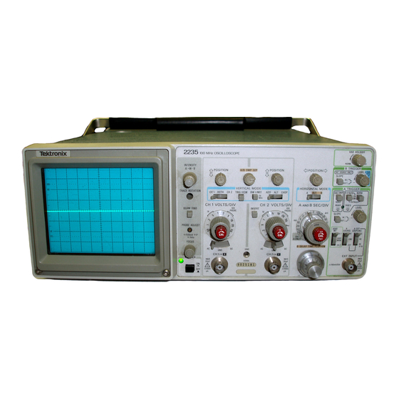
2235 Service ατο 6-ο 1 e 2235 Oscillosco... -
Page 10: Specification
"Options and Accessories" section (Section 5) of this manual . Your Te ktronix re presentative, local Tektronix ield Office, or Te ktronix prod uct catalog ca n also rovide accessories Ph ysical characteristics of the instru me nt are liste d n Τα-... -
Page 11: Electrical Characte Ristics
Sp ecification-2235 Service Ta ble 1-1 lectrical Characte ristics Ch aracteristics Performance equ irements Supplemental Info rmation VERTICA L DEFLECTIO N SYSTEM Deflection acto r 5 mV per ivision to 5 V er division gain is adjusted with V O LTS/DIV switch R ange 2 mV per division to 5 V per ivision... - Page 12 pecification-2235 Service Table 1-1 (cont) equ ir em e n ts upplemental Info rmation Characte ristics Performance VERTICA L DEFLE CTIO N SYST EM andwidth Limiter Upper limits (-3 dB) andpass at 20 MHz ± 10% . 500 kH z ±30% .α Chop Mode Switching In put Characteristics esistance...
-
Page 13: M Aximum Input Voltage
pecificatio n -2235 Service Ta b le 1-1 (cont) Characteristics erfo rman ce equ irements Suppleme ntal Info r mation TRIGGER SYST EM Α TRIGGER Sensitivity xter n al trigger signal from α 50 Ω sour ce driving α 50 Ω coaxial ca ble Ρ-Ρ... - Page 14 pecificatio n -2235 Service Ta b le 1-1 (cont) h a r acte r istics erfo rma n ce eq u i r eme nts Supple m ental Information O R IZONTAL EFLE CTION SYST EM Sweep Cali b rated R an ge 0.5 s er division to 0.05 As Α...
-
Page 15: Line Fuse
Specificatio n-2235 Service Ta ble 1-1 (cont) Characte ristics Performa nce equ irements Suppleme ntal Info rmation Χ-Υ OPERATIO N (Χ 1 AG NIFICATIO N) Deflection Factors Same as ertical Deflection System (wit h V OLTS/DIV Varia ble co ntrols in CA L dete n t). -
Page 16: De Rating Curve For Ch 1 Or Χ, Ch 2 Or Υ
pecification-2235 Service O L TS (DC PLU S PEAK AC)l )2 .5 ν 10 KH z 50 KH z 100 ΚΗτ 500 ΚΗτ 1 MH z 100 MHz FRE Q UEN CY 4207-28 igu re 1-1 . axim um inpu t voltage vs. fre que ncy e rati ng cu rve for CH 1 OR Χ... - Page 17 pecification-2235 Service Ta ble 1-2 Environmental Characte ristics h a racteristics Descri ption ΝΟΤΕ e instrument meets t equi ts of s 4.5.5 .1 .3, MIL-T-288000, p 4.5.5.1 .4, and 4.5 .5.1 .2.2 for Ty e ΙΙ/, Class 5 eq ipme t, exce e ot...
-
Page 18: Physical Characteristics
Specification-2235 Service Table 1-3 Physical Characteristics Characteristics Description Weight With Power Cord With Cover, Probes, and Pouch 7.1 kg (15.7 lb). Without Cover, Probes, and Pouch 6.1 kg (13.5 lb). Domestic Shipping Weight 8.2 kg (18.0 lb). Height With Feet and Handles 137 mm (5 .4 in). -
Page 19: Preparation For Use
2-1, and is presente applicable) . the "Accessories" page at the back of this manual- Contact your Tektronix representative or local Tektronix Field Office ditional power-cord information . slightly rotate the fuse-hol er cap coun- 2. Press in an terclockwise to elease it . -
Page 20: Operating Instructions
erating I nstructions-2235 Service einstall th e fuse (o r r eplacement fuse) and the fuse- FUSE h olde r ca p. N ST RUMEN T COO LI N G CAUTION CA UTION CσΝΤιΝυεσ TO AVOID ELECTRIC FIRE PRCTECTION SHOCK THE POWER C E ONLY WITH PE CI F IE D eq uate instr u ment cooling . -
Page 21: Vertical
Operating Instructions-2235 Service 2235 , ο dd ron i c ο ο ο ο 4207-04 ower, display, and probe adjust co n t r ols, conn ector, and indicator. igure 2-3 . Α an d Β INTENSITY Co ntrols- Dete r mi n e the right- n ess of the Α... -
Page 22: Horizontal
erati ctio s-2235 Service Χ and C Υ Co ecto rovi e for sweep. T e switc ing rate is a roximately 500 lication of external sig als to t ts of t e ver- z. T is mo e is usef l for viewing tical deflection system or for an Χ-Υ... - Page 23 O perating Instructions-2235 Service 10, POSITION VER TICA L MODE --' ; TRIG AW LΙΜΙΤ /DΙΥ VOLTS/01V' CH1 VOLTS ιχνεκΤ CH 2 Γσχ εχσ~ε ,_, s~_rΡσσε " igure 2-5. orizontal co ntrols. Α and Β SE CIDI V Variable Control -Provides contin- B--Horizontal eflection is provid e d...
-
Page 24: Trigger
O perating Instructions-2235 Service IN-When p sh button is presse in, s eep is trig- TRIGGER gere from the negative-going slope of the trigger signal . efer to Figure 2-6 for locations of items 25 through 34 . TRIGGER Switches-Three ush-button etermine the trigger mode for switches that... -
Page 25: Rear Panel
Operating Inst ructions-2235 Service ODE-The inte rnal trigge r source is deter- mi ned by the signals selected for isplay by the VERTICA L MODE switches . efer to Figure 2-7 fo r location of item 35 . CH 2-The sig n al applied to the CH 2 OR Υ np ut conn ector is the source of the trigger signal . -
Page 26: Operating Considerations
Operating Instructions-2235 Service G CO ATIO he following basic operating information tech iques should be co n si before atte pting to ma k e any mea- surements with yo ur instrume I ST O R LEFT 11TH R RIG HT R TICA L VERTICA L G RATIC ULE... -
Page 27: Operator's Adjustments
Operating Inst ructions-2235 Service . Con n ect th e ro be tip to the signal so urce an d wait level difference is more than 10 times the OLTS/DIV several seconds for the input coupling capacitor to c h a r ge . switch setting : 4. -
Page 28: Oscilloscope Displays
Operating Instru ctio n s-2235 Service , . . ENEWENNEEN FIRM αιΝΕ ιΕ~ . ιΜειειιιει R COW SATED 4207-11 ig ur e 2-9 . Probe compensation, OSCILLOSCOPE DISPLAYS H orizontal CTIO The proce e in this section will allow you to set up an ΑΙΒ... -
Page 29: Signal Display
Operating Instructio ns-2235 Service 3 . Pull out the SEC/DI V Varia ble no b (Χ10) to obtain 2. Press in the POWER switch butto n (on) and allow the sweep magnification . instrument to warm up or at least 20 minutes . orizo n tal POSITIO N control for precise NTEN SITY control for desired disp lay 4. -
Page 30: Χ-Υ Display
Operating Instructions-2235 Service 5. Adjust the Β DELAY TIME POSITION control to move 2 . Use equal-length coaxial cables, or the two 10 Χ he intensified zone to the leading edge of the first pulse of robes supplied with he instrument, to apply the orizontal interest ;... - Page 31 e rating Inst ru ctio ns-2235 Service layed, inte rrupt the trigge r- To c hange the field that is dis V Field-rate Signal Displayi ng α ing either epeatedly setting the AC-G N D-DC switch to 1 . Obtain α Signal Display of the desired TV signal (see GN D or by disconnecting and reconnecting the signal from rocedure).
-
Page 32: Theory Of Operation
Section 3-2235 Service HE O R Y O F O PER ATIO N CTIO SECTION ORGAN IZATIO N NTEGRATED CIRCUIT DESC RIPTIONS This section of the manual contains α general summary of instrument functions followed y α detailed descri ption of Digital Logic Conventions each major circuit. -
Page 33: General Description
Theory of Operation-2235 Service ENER tions the Β trace with respect to the Α trace when Alt Hori- NOTE zontal ode is selected . When reading this genera/ circuit escription of the 2235 Oscilloscope, refe r to the basic block diagram (Fίgure 9-4) and to the etailed lock dίagram (Fίgure... -
Page 34: Detailed Circuit Description
Theory of Operation-2235 Service lanks the crt isplay signal from the Chop Oscillator circuit In the Χ-Υ mo de of operation, the Channel 1 signal from etween the vertical channels . while switching he Χ-Υ Amplifi- the Internal Trigger circuitry asses through er to the Horizontal Preamplifier . -
Page 35: B Uffer Amplifier And Gain
heory of Operation-2235 Service ΗΙ GΗ-Ζ FR O M BUFFER TC H I NG τ0 ATTENUATOR VERT CA L INPU T AST PATH VERTICAL =1 , = 10, CO UPL ρ13, Q18 PREAMP =1 , = Ζ , =1 θ0 =4, +10 BUFFER LOW PATH... -
Page 36: Vertical Preamplifiers
Theo ry of Operation-2235 Service Channel 1 a n d C hannel 2 output signals are then conducted transistors connected to R38 a n d th e overall gain of the to ground . Zener diode VR 200 turns on and CR200 and ecrease. -
Page 37: Vertical Output
eory of O ation-2235 Service NNEL NNEL Ι TC 13 θ OGIC R2 0 0 , CR20 1 , S55θ , U54ΘΑ CR2θ2, CR2θ3 U5408, U537A U537C, U537D NNEL SWITC α206-12 re 3-2. of t el Switc g ci itry . ling capacito C547 a esistors... -
Page 38: Α/Β Sweep Separation Circuit
y of O eratio -2235 Service The output stage of the Amplifier utilizes two totem-pole line . The Α&Β ΙΝΤ switch selects either Channel 1 or Chan- transistor airs, 0254-Q256 and 0255-Q257, that convert nel 2 as the trigger source, and the Α SOURCE switch se the collector currents of Q230 and Q231 to roportional out- lects between internal, line, or external trigger sources. -
Page 39: Internal Trigger Amplifier
Theory of Operation-2235 Service CHANNEL 2. For triggeri ng fr om C hannel 2, th e Α & Β ΙΝΤ Signal current is app lied to the emitters of 350D and switch is set to CH 2. One input eac h of U555C and U555D 350E. -
Page 40: Α Trigger Generator
Theo ry of Operation-2235 Service ENER Α biased on an d U 460A and 460D are iase d off. or the negative slope osition, the transistors reverse states to in- vert the comparator outpu t olarity. Th e Α Trigger Generator, shown on Diag ram 3, supplies trigger signals to the Α... -
Page 41: Α M Iller Sweep Generator
eory of O eration-2235 Service ramp is initiated w en 0576 is biase off. T als t at are used to ge erate correct timing of t e crt Α swee e timi g ca pacitors can c arge at α ing and intensity levels used for viewing t lay. -
Page 42: Α Sweep L Ogic
Theory of Operation-2235 Service y R569 and the output will follow the 532D is Α Swee p Logic rovided by the Q output of U502 . If trigger signals signal ogic circuitry controls swee p generation, The Α Sweep eing received by U502, the output of U532D will e HI as α... -
Page 43: Β M
Theory of Operation-2235 Service delay time (Runs After Delay) or upon receipt of the first tentiometer R6440 . The output of the comparator is used to trigger signal after the delay time as elapsed. This delay initiate α Β Sweep and to control the Β Ζ-Axis ogic circuit time is α... -
Page 44: Alternate Display Switching L Ogic
Theory of Operatio n-2235 Service output states, two Α Sweeps are requ ired to cause the flip- O at the end of the Α Sweep and ca use an Sync li ne will go immediate resetting of the Ge n erato r. In either case, α new flop output levels to switch. -
Page 45: Horizontal Preamplifier
heo ry of Operatio n-2235 Service of the Alternate Display Switc h ing ogic ci rcuit . See igure orizontal X10 Gain is set by th e resisto r n etwork con 3-4 for th e bloc k diagram of the orizontal Amplifier. -
Page 46: Horizontal Output Amplifier
Th eo ry of Operatio n-2235 Service Wh en the Χ-Υ mode is not selected, Q756 is biased on and Q829 with he portion thr ough Q829 riving the shunt he Χ -Axis sign al is s hun ted to ground. feedbac k output amplifier consisting of 0835, Q840, and Q845. -
Page 47: Dc Restorer
Th eory of Operation-2235 Service BEAM FIN D switch S390 co ntrols the ase bias voltages voltage will e clampe d wh enever the ositive eaks reac h α of Q825 and Q829 . Wh en the BEAM FI ND bu tton is out, level that forward iases C R 851 . -
Page 48: Power Supply And Probe Adjust
Th eory of Op e r atio n-2235 Service hroug h C854 to reverse ias CR854 and to forward rotected from large voltage transients y su pp ressor CR855. The increased charge of C854 is then transferred to VR 901 . Conducted interference originating within t h e ower C855 as C854 discharges toward the Ζ-Axis output level. -
Page 49: Crt Supply
Theory of Ope ration-2235 Service ositive voltage from the lead of Τ944 whic h is co nn ected to it h Q9070 off, C907 charges to the output voltage of ase of the cond u cting transistor and reinforce condu c- th e Power Input circuit. -
Page 50: L Ow-Voltage Supplies
Theory of Op eratio n-2235 Service of Q885 . The emitter voltage of Q804, set by the Α ΙΝΤΕΝ - V su ply is produced y CR967, CR970, C968, 971, and C970 . lied to the emitter of Q885 t h roug h SITY control, is ap 885. -
Page 51: Performance Check
Sectio n 4-2235 Service PERFORMANC E C HECK PROCED URE CTIO QU I PMENT TEST PURPOSE The test equi pment listed in Table 4-1 is α complete list of The "Performance Chec k Procedu re" is used to verify the he "... -
Page 52: Preparation For Checks
4 . Ca ble (2 re qu ired) Im pedance : 50 Ω. engt h: 42 Signal interconnectio n . Tektronix Part Number 012- in . Co nn ectors : BN C . 0057-01 . 5. Termination Im p edance: 50 Ω. - Page 53 Purp ose Test Equipme nt 8. Τ-Connector Co nnectors : BN C. I Sig nal inte rco nn ection . Tektronix Part Numbe r 103- 0030-00 . 9. Adapter Connectors : BN C- M ale-to- Sig nal inte rconn ection .
-
Page 54: Vertical
Performance Chec k Procedu r e-2235 Service VERTICAL me nt Required (see Ta ble 4-1) : 50-Ω BN C Termination (Item 5) Cali bration Generator (Item 1) Du al-I np ut Coupler (Item 6) eveled Sine-Wave Generator (Item 2) 10 Χ Attenuator (Item 7) 50-Ω... - Page 55 erfo mance C e-2235 Service k Pr c. Ad ust t TS/DI aria le control to Ι. arts and c. ce α 4.4-divisio lay. Set t TS/DI switc to 10 mV. m. Discon nect the test equi pment from th e instrume nt. d .
-
Page 56: Settings For B
Performance Chec k Procedure-2235 Service b. Connect the leveled sine-wave ge nerator outpu t via α e. Disconnect the test equ ipment from the instrument. 50- Ω cable and α 50- Ω te rmi n atio n to t h e CH 2 OR Υ in connector. - Page 57 Perfo rma n ce Chec k Pr ocedure-2235 Service c. Set the generator to produce α 50-MH z, 5-division ivisio n or less . ο. CHE CK-Display am plitud e is 0.6 display. ρ. Disconnect the test equi pment from th e instrument . d .
-
Page 58: Horizontal
Performance Check P rocedur e-2235 Service ui p ment Re uired (see Table 4-1): Cali bration Ge nerator (Item 1) 50-Ω BN C Cable (Item 4) eveled Sine-Wave Generator (item 2) 50-Ω BN C Terminatio n (Item 5) Time-Mar k Generator (Item 3) ITIA 1. -
Page 59: Settings For Timing Accuracy Checks
erformance Check Procedure-2235 Service OSITION control to align he first se the orizontal Table 4-4 eyond the start of the swee p with time marker that is 25 ns Settings for Timing Accuracy Checks he second vertical graticule line . Time-Mark Generator Setting SEC/DIV CHECK-Timing accuracy is within 3% (0 .24 division... -
Page 60: Settings For Delay Time Accur Acy Checks
Performance Chec k Pr ocedure-2235 Service 3. Check Delay Time Dial Range an Accu racy η. CHE CK-The Β DELAY TIME POSITIO N dial setting is between 8 .905 and 9.095 . α. Set the Β DELAY TIME POSITIO N dial fully cou n terclockwise . - Page 61 P erfo rma nce Chec k Pr ocedure-2235 Service Discon n ect t h e test eq uipment from the instrument . 4. Chec k Delay itte r α. Set : Α S EC/DI V 0 .5 ms Β S EC/DI V 0 .5 μs 6.
-
Page 62: Trigger
Perfor ma nce Check Proced ur e-2235 Service Eq ui pme nt R equired (see Ta ble 4-1) : 50-Ω BN C Termi natio n (Item 5) eveled Si ne-W ave Generator (Item 2) 50-Ω BN C Ca ble (Item 4) to 50 m OLTS/DIV switc ε. - Page 63 P e r fo r mance Ch ec k Pr oce dur e-2235 Service k. Set the generator to pr oduce α 60-MH z, 1 .0-divisio n . Pus h in and old the TRIG I EW bu tton . display.
-
Page 64: Chec Ks
Performance Check Procedure-2235 Service e. CHECK-READY LED goes out and α single swee p ot triggered (no trace) at either CHECK-Display is occurs . extreme of rotation . 4. Check Single Sweep peration NOTE α. Adjust the Α TRIGGER LEVEL control to obtain α sta- le display. -
Page 65: External Z-Axis And Probe Adjust
Perfo rmance Chec k Pr ocedure-2235 Service XTERNA L Z-AXIS AN D PROBE ADJUST (see Ta ble 4-1) : quipme nt Re uire eveled Si ne- Wave Generator (Item 2) BN C Τ-Connector (Item 8) 10 Χ Probe (provided with instrume n t) Two 50-Ω... -
Page 66: Adjustment Procedure
Section 5-2235 Service ADJUST MEN T PROC EDURE CTIO Table 4-1 . Wh en considering use of equipment ot her than PURP OSE that recommended, utilize the " Minimum Sp ecification" col- etermine whet h er availa ble test equi pment will The "Adjustment Procedure"... - Page 67 djustment Procedure-2235 Service All test equi pment ite m s listed in Table 4-1 are equired an internal adjustment setting f α erformance Characteris- to accomplish α complete Adjustment rocedure. At the be- tic cannot be met with he original setting. If it is necessary ginning of each ubsection there is an equipment-re quire d change the setting of an internal adjust m ent, check Table...
-
Page 68: Power Supply And Crt Display
Adju st ment Pr ocedure-2235 Service NDEX TO ADJUSTMEN T PROCE DURE orizontal STEPS 1 . Adjust Horizontal Am lifier Gain ... . . 5-14 2 . Adjust Χ10 Horizontal Am lifier Gain . -
Page 69: Procedure Steps
Ad justment roce dure-2235 Service UPPL T DIS quipment equire (See Ta ble 4-1): eveled Sine-Wave Generator (Item 2) Digital Voltmeter (Item 10) Time-M ar k Generator (Item 3) DC Voltmeter (item 12) 50-Ω BN C Cable (Item 4) Screwdriver (Item 13) 50-Ω... -
Page 70: Chec K Hig H-Voltage Su Pp Ly
Adjustme nt Pr oced ure-2235 Service 2. Chec k Hig h-Voltage Sup c. Set the generator to ro d uce α 50-kH z, 4-division display. d . ADJU ST-Astig (R874) and the front-panel OC US WA RN I N G control for the est defi ned wavefo rm. -
Page 71: Vertical
Adju stment Pr ocedure-2235 Service VERTICA L quipment eq uired (See Ta ble 4-1) : Calibration Generator (Item 1) 10 Χ Attenuator (Item 7) eveled Sine-Wave Generator (Item 2) Adapter (Item 9) 50-Ω BN C Cable (Item 4) Screwdriver (Item 13) 50-Ω... -
Page 72: Ad Just 2/5 Mv Dc B Alance
djustme nt Procedure-2235 Service b. Position the trace on th e ce nte r horizontal graticule ala n ce (R33 and 2 . Adj ust 2/5 mV DC line using the Channel 2 POSITIO N control. OLTS/DI V switch to 5 mV . α. -
Page 73: Adj Ust V Ertical Gain
Adjustme nt Proce du re-2235 Service AD JU ST-C h 1 MF/LF Comp (C3) and Ch 1 MF /LF VOLTS/DI V switch. If trace s hift is observed, repeat Step 2 Gain ΒαΙ (R47) for the best front corner nd flat to of this rocedu re. -
Page 74: Attenuator Compensation Ad Ju Stments
Adjustment Procedure-2235 Service Set the cali bration generator to produce α 20-mV Ta ble 5-4 Attenuator Compensatio n Adjustme nts signal . Cha nn el 1 Chann el 2 Adj ustment Ι ottom of the signal on the center orizontal c. -
Page 75: 10. Chec K Alte Rn Atio N Operatio N
Ad ju stme n t Pr ocedure-2235 Service υ . arts b throug h s for Chann el 2. 12 . A ju st ig h-Fr equ ency Compensation (C237), Delay ine Compensation ( R240 and R241), and Ch a nn el 2 ig h-Fre ue ncy Compensation (C180) ν. -
Page 76: Adjust 2-Mv Pea King Com Pensation
Adjustment Procedur e-2235 Service Ι . Move the ca ble from the CH 1 OR Χ input connector to c. Wh ile ol ding in the TRIG I EW button, use the Α he CH 2 OR Υ in put connecto r. Set the VERTICA L MOD E TR IGGER LEVEL control to ve rtically ce nter the is play. -
Page 77: Settings For B Andwidth Chec Ks
Adjustment Proced ure-2235 Service c. CHE CK-Display am plitude is 4.2 divisions or greater line by rotati ng the Chan nel 2 POSITIO N co ntrol fully clock- as the generator outpu t frequency is increase d up to the wise and countercloc kwise respectively . - Page 78 Adju stment Procedure-2235 Service g. C HE C K -Display amplitude is 0.05 division or less . Ad just the CH 1 or CH 2 OLTS/DIV Variable co ntrol for minimum is play am plitud e. Disco n nect t h e test equi p me n t from the instrument . Ι...
-
Page 79: Horizontal
Adju stment Proce ure-2235 Service quipme nt equired (see Table 4-1) : Calibration Generator (Item 1) 50-Ω BN C Termination (Item 5) eveled Si ne- Wave Generator (Item 2) Test Oscilloscope (Item 11) Time-Mar k Generator (Item 3) Screwdriver (Item 13) 50-Ω... -
Page 80: Adjust Χ10 Horizontal Am P Lifier Gain
ju stme nt Pr ocedu re-2235 Service 2. A j ust Χ10 orizontal Am plifier Gain (R754) 5. Chec k Position ange α . Set: α. Set : HOR IZONTA L MOD E Α Ch annel 1 AC-G ND-DC Χ10 Magnifier On (knob out) Α... -
Page 81: Adjust Delay Dial Timi Ng
Adjustment Procedure-2235 Service 7 . Ad just Delay Dial Timi ng ( R646 and 652) e. AD JU ST- Β ig h Speed Timing (C713) for 1 time ma rker er division over the center 8 divisions . α. Set : HOR IZONTA L M OD E Α... -
Page 82: Settings For Timi Ng Accuracy Checks
Adjustme nt Procedure-2235 Service i. Use the orizontal POSITIO N control to align the first Ta ble 5-6 time marker that is 25 ns beyond the start of th e sweep with Settings for Timi ng Accuracy Checks he second vertical graticule line . Time-Mark Ge nerator Setting j. -
Page 83: Settings For Delay Time Accuracy Checks
Adju stme n t Pr ocedure-2235 Service g. Align the start of th e Α Swee p with he 1 st vertical ρ. Set: graticule line using the orizontal POSITIO N cont r ol . Α SE C/DI V μs Β... -
Page 84: 13 . Check Sweep Separation
Adjustment Procedure-2235 Service 13 . Check Sweep Separation b. Set the generator to roduce α 5-division orizontal display at an output frequency of 50 kHz. α. Set: HORIZONTAL MODE Α and Β SEC/DIV 0.5 ms ε. ncrease the generator output frequency to 3 MHz . b. -
Page 85: Trigger
Adjustme nt Procedur e-2235 Service quipme n t R eq uired (see Table 4-1) : eveled Sine- W ave Generator (Item 2) 10 Χ Atte nu ator (Item 7) 50-Ω BN C Cable (Item 4) Digital oltmeter (Item 12) 50- Ω BN C Termination (Item 5) Screwdriver (Item 13) AD JU ST MENT OCATIO NS 1... -
Page 86: Adju St Slope B Alance
Adju stme nt Procedur e-2235 Service b. Connect the leveled sine-wave gene r ator output via α 5. Chec k Inte rnal Trigge ring 50-Ω cable and α 50-Ω te rmi nation to the CH 1 O R Χ in p ut α. -
Page 87: 6 . Chec K External Trigge Ri Ng
Adju stme nt Pr oced ure-2235 Service j . Set: 6 . Chec k External Trigge ri ng H OR IZONTA L MOD E Α α. Set: Α SEC/DI V 0 .1 VERTICA L MOD E CH 1 Χ 10 agnifier On (knob out) HORIZONTA L MOD E... -
Page 88: 8. Check Single Sweep Operation
Adjustment Proce dure-2235 Service c. Press in the SGL SWP button . The READY LED CHECK-Display is triggered along the entire positive should illuminate and remain on . slope of the waveform as the Α TRIGGER LEVEL control is rotated . d . -
Page 89: External Z-Axis And Probe Adjust
A djustment Procedure-2235 Service XT ERNA L Z-AXIS AN D PROBE AD JUST quipme nt Requi red (see Table 4-1): eveled Sine-Wave Generator (Item 2) BN C Τ-Conn ector (Item 8) Two 50-Ω BN C Ca bles (Item 4) 10 Χ Probe (provide d with n strument) 50- Ω... -
Page 90: Maintenance
Section 6-2235 Service AI NTENANC E his section of the manual contains information for conducting reventive maintenance, troubleshooting, and corrective maintenance on the 2235 Oscilloscope . SITI STATIC-S recautions are applicable when perform- Table 6-1 The following ing any maintenance involving internal access to the Susceptibility instrument . -
Page 91: Preventive Maintenance
95% water. efore using any trouble in the instrument ; therefore, it is important that the oth er typ e of cleaner, consult your Tektronix Service cause of overheating be corrected to revent recurrence of Center or rep r esentative. -
Page 92: And Replacement
M ai n te n a n ce-2235 Service Table 6-2 E xte rn al In spectio n h ec k list Ins pect Ι epai r Action Item Cabinet and Front Crac k s, scratc h es, deformations, and damaged Touc h up paint a n d re place efective arts . -
Page 93: Lubrication
aintenance-2235 Service 2. Spray wash dirty arts with etergent-and-water Spray only for approximately five seconds, using an solution ; then use clean water to thoroughly rinse them . atomizing spray device . he switch and the circuit board on which it is 3 . -
Page 94: Troubleshooting
ce-2235 Service OOTI UBLE rd L CTIO ocatio An ill stration icting t e location of α circ oard reventive mai ance performed on α egular basis in t e inst ment is s own on t e foldout age ad ould reveal most otential lems... -
Page 95: Troubleshooting Equipment
Maintenance--2235 Service Note that some troub les hooting-proce ure boxes on b ination, in dicates Te ktronix rown-gray-green stripe co eac h c h a rt contain numbers along their lower e ges. These Part e r 152-0185-00) . The catho e an e en s of... - Page 96 ai nte n a n ce-2235 Service OOTI UBLE WA RN I NG rocedure is a r ra nged n an order that en- The following ables checking simp le trouble ossi bilities efore uiring Da ngerous poten tials exist at several points through- more extensive troub les hooting .
-
Page 97: Power Supply L Imits And
ce-2235 Service sert t et sig al ti to t e first test poi dicate le 6-4 a e bayo et ground tip to t assis ground near t e test point. T ipple val es listed in Table 6-4 are based on α system limited in band width to 30 kH z To avoid electric shock, always disconnect the instru- (greater bandwidt h will result in ig her readings). - Page 98 ai ntena nce-2235 Service DIOD ES. Α diode can be c h ec ked for either an open or α ages exceeding those give n for typical emitter-to-collector y meas u ring the resistance betwee n ter- s horted co ndition values coul d indicate eit h e r α...
-
Page 99: Corrective Maintenance
Office or representative . describes special techniques and procedures equired to replace components in this instrument . If it is ecessary to ship your instrument to α Tektronix Service Center for repair rdering arts r service, refer to the "Repackaging for hipment"... -
Page 100: Transistors And Integrated Circuits
ai ntena nce-2235 Service Table 6-5 ainte nance Aids Desc ription Specifications Usage xample 1 . Soldering Iron 15 to 25 General soldering and Antex Precision odel C. ~ unsoldering. 2. Torx Screwdrivers To rx ti p s #Τ7, #Τ9, #Τ10, Assembly and disassembly. -
Page 101: Soldering Techniques
ai ntenance-2235 Service The heat-si nk-mounted power su pply transistors are in- CA U TIO N sulated from the eat sink. In addition, α eat-sink com- pound is used to increase eat transfer capabilities. ei nstall the insulators and replace the eat-sink compou nd Attempts to unsolder, remove, and esolder leads... -
Page 102: Nstructions
ai n te n ance-2235 Service 4. Insert the leads in to t h e oles of t h e boa r d so th at th e To reinstall th e ca binet, erform the following steps: replacement compo n ent is positioned th e same as th e origi- . -
Page 103: Power-Supply Shield
ai ntena nce-2235 Service 1 . Remove t h e screw from th e plastic ower-s upply cov- 2. Unplug the crt anode lead connector from the ig h- er on t h e ottom section of the ai n circuit oard. -
Page 104: F Ilter Circuit B Oard
Mai ntena nce-2235 Service emove the Power-Supp ly shield (see t h e " Power- Attenuato r Circ u it oa rd Supp ly S hield" removal procedu re). erform the fol- To remove t h e Attenuator circuit oard, lowing steps: oar d by emove the five wires to the... -
Page 105: Timing Circuit B Oard
ai n te n ance-2235 Service el circuit board connectors and hat the two resistors (sol- 3. Use α 1/16-inch Hex-key wrench to loosen two set dered to the ottom of the Attenuator circ uit board) do not screws securing the Α EC/DI V dial to the shaft assembly . -
Page 106: B Ottom Shield, Attenuator A Nd
aintenance-2235 Service rocedure and steps 11 through 14 of t h e ei nstall the SEC/DI V V a r iable knob nto its shaft reinstallation 14 . orizontal and right-si e up) and tighte n "Timing Circ uit oard" reinstallation rocedu re . -
Page 107: M Ain Circuit B Oard
ai nte nan ce-2235 Service NOTE 16 . esolder the resistor to the ΕΧΤ INPUT center con- nector and the wire stra p to t h e ΕΧΤ I NPUT ground lug At this oint, a ny component on the Front- P anel cir- (unsoldered in step 4) . - Page 108 ainte nance-2235 Service emove the POWER switch extension-s haft assem- 16 . Use α vacuum-desoldering tool to un solder the 39 ly by first pressing in the POWER button to the ON posi- wire straps (connecting the ain circuit oa rd to the ront tion .
-
Page 109: Repackaging For Shipment
ce-2235 Service 27 . econnect Ρ 9001 an Ρ 9002 to t ain ci cuit at can e contacte . Include complete instr t serial (remove in ste 8) . boar er a α descri tion of t e service requi e P O n w h 28 . -
Page 110: Options
Section 7-2235 Service OPTIONS There are currently no options for the 2235, except the optional power cords previously described in Section 2 . - Page 111 . Changes to Tektronix instruments are sometimes made to Assembly numbers are also marked on the mechanical exploded n the arts ist . The component...
-
Page 112: Replaceable Electrical Parts
eplaceable lectrical arts-2235 Service ROSS INDEX-MFR. CODE NUMBER TO ANUFACTURER fr . Code anufacturer Address City, State, Zip OOOFG RIFA ORLD PRODUCTS INC. 7625 BUSH LAKE RD Ρ.Ο. BOX 35263 INNEAPOLIS, MN 55435 OOOFG RIFA WORLD PRODUCTS INC. 7625 BUSH LAKE RD Ρ. - Page 113 SIDNEY, NY 13838 CO MP ONENTS DI VISIO N BE AVER TO N, OR 97077 Ρ Ο BOX 500 80009 TEKTRONIX, I NC. ORR ISTOWN , NJ 07960 ELECTRA- MID LAND CO RP ., MEPCO DI V. 22 CO LUMBIA ROAD 80031 CHICAGO, I L 60630 5555 Ν...
- Page 114 Service Tektronix Serial/ Model No . Component No . art No . Dsco n t ame & Descri ption Code art Nu mber Α1 670-7614-00 OA RD ASSY : MAI N 80009 670-7614-00 Α 672-1064-00 OA RD ASSY :ATT ENUATO R/TIMING,W/S HI EL D...
- Page 115 e p laceable lect r ical Parts-2235 Service Te ktronix Serial/Model No. Component No . art No . Dscont ame & Desc ription Code fr Part Nu m be r C405 281-0773-00 CAP., FXD,C ER DI :0 .01 UF ,10%,100V 04222 SA201C103 KAA AlC408...
- Page 116 eplaceab le lectrical arts-2235 Service Te ktronix Se rial/ Model No . Component No . art No . Dsco nt ame & Desc r i ption art Nu mber AlC782 281-0775-00 CA P., FXD,C ER DI :0 .1 UF ,20%,50V 04222 ΜΑ...
- Page 117 laceable lect ical arts-2235 Service ial/ onix odel No . Code Dsco ame & Desc onent No . art No . S EM 01295 4152 D DEVICE : SI ,150 152-0141-02 S EM 4152 D DEVICE : SI ,150 01295 152-0141-02 S EM 4152...
- Page 118 Parts-2235 Service Tektronix Serial/Model No . Component No . art No . Dscont ame & Description Code art Number AlCR956 152-0414-00 SEMICOND DEVICE : SILICON,200V,0 .75A 12969 UTR308 AlCR957 152-0414-00 SEMICOND DEVICE : SILICON,200V,0 .75A 12969 UTR308 AlCR960 152-0414-00 SEMICOND DEVICE : SILICON,200V,0 .75A...
- Page 119 Service Tektronix Se rial/ Model No . Dsco n t ame & Desc ri ption fr Part um be r Component No . Code art No. Α10419 151-0711-00 TRANSISTOR : SILICON, ΝΡΝ 04713 SP S8224 TRANSISTOR : SI LICO N, NPN 04713 Α10420...
- Page 120 Service Tektronix Se rial/ Model No . Co mp o n ent No . art No . Dsco nt Code ame & Descriptio n art Number Al R121 321-0123-00 RE S., F XD, FI LM :187 ΟΗΜ,1%,0.125W...
- Page 121 arts-2235 Service lectrical ep laceable Te ktronix Serial/ Model No . art Number Dsco nt ame & Descri ption Component No . art No . MFF1816G487 R O F RES., FXD,FI LM :487ONΜ ,1%,0.125 W 91637 Al R216 321-0163-00 MFF1816G487 R O F RE S., FXD,FI LM :487 ΟΗΜ...
- Page 122 lect r ical eplaceable arts-2235 Service Te ktronix Se r ial/Model No . Component No . art No . Dsco nt ame & Description um ber Al R305 315-0152-00 RE S., FXD,C MP SN:1 .5 K ΟΗΜ ,5%,0.25W 01121 CB1525 Al R306 315-0470-00 RE S ., FXD,C MP SN:470 HM ,5%,0.25W...
- Page 123 e p laceable lect r ical Parts-2235 Service Te ktronix Serial/ Model No . Component No . a rt No . Dsco nt ame & Description umber Al R386 315-0911-00 RE S., FXD,C MPSN:9100HM ,5%,0.25W 01121 C B 9115 All R389 315-0100-00 RE S., FXD,C MPSN:100 HM ,5%,0.25W 01121...
- Page 124 eplaceable lect rical arts-2235 Service Te ktronix Serial/ Model No . Component No . art No. Dscont Code ame & Desc ri ption art Number Al R465 315-0431-00 RES., FXD,C MPSN :430O N Μ,5%,0.25W 01121 CB4315 Al R469 315-0820-00 RE S., FXD,C MP S N :82O NΜ,5%,0.25W 01121 CB8205 Al R470...
- Page 125 eplaceable lectrical arts-2235 Service Te ktronix Se rial/ Model No . art Nu mber Code Dsco nt ame & Description Compone nt No . art No . 01121 CB2225 RE S., FXD,C MPSN:2 .2 K ΟΗΜ,5%,0.25W 315-0222-00 Al R571 C B1025 RE S., FXD,C MPSN:1 Κ...
- Page 126 eplaceable lect rical arts-2235 Service Te k tronix Se rial/ Model No . Component No . art No . Dscont ame & Description art Nu mber Al R823 301-0512-00 RE S., FXD,C MPSN :5 .1 K ΟΗΜ ,5%,0.50W 01121 ΕΒ 5125 Al R825 315-0750-00 RE S., FXD,C MPSN:75 OHM,5%,0.25W...
- Page 127 lect r ical eplaceable arts-2235 Service Te ktronix Se rial/ Model No . Component No. art No . Dscont ame & Descriptio n Code umber Al R927 315-0104-00 RE S., FXD,C MP S N :100 K ΟΗΜ ,5%,0.25W 01121 CB 1045 Al R928 315-0682-00 RE S., FXD,C MP SN:6.8 K ΟΗΜ,5%,0.25W...
- Page 128 eplaceab le lect rical arts-2235 Service Te ktronix Serial/ Model No . Component No . art No. Dscont ame & Description Code art Nu mbe r VR 200 152-0149-00 S EM ICON D DEVICE : ΖΕΝER ,0 .4 W,10V,5 % 04713 SZG35009 K3 Al VR 645...
- Page 129 Service eplaceable Tektronix Serial/ Model No . fr Part Nu mber Dscont ame & Desc ription Component No . art No . 57668 JWW-0200ΕO BU S CO NDUCTOR:D UMMY RE S,2.375,22 AWG 131-0566-00 Al W976 JWW -0200ΕO BU S CO ND U CTOR:D UMMY RES,2.375,22 AWG...
- Page 130 Service Tektronix Serial/Model No . Component No . art No . Dscont ame & Description Code art Number Α2 670-7561-00 OARD ASSY :ATTENUATOR 80009 670-7561-00 Α2ΑΤ 1 307-1014-06 ATTENUATOR,FXD :100 80009 307-1014-06 Α2ΑΤ2 307-1013-00 ATTENUATOR,FXD :10X 80009 307-1013-00 Α2ΑΤ51...
- Page 131 eplaceable lectrical arts-2235 Service Te ktronix Serial/Model No . fr Part Nu m be r Code Dsco nt ame & Descri ption Com ponent No . art No . RE S., FXD,C MP S N:5 .6 ΟΗΜ,5%,0.125 W 01121 BB 56G5 317-0056-00 A2 R4 RE S., FXD,FI LM :500 K ΟΗΜ...
- Page 132 Se rvice Tektronix Serial/ Model No . Component No . art No . Dscont ame & Desc ri ption Co de f r Part Number A2 R75 311-1568-00 RES.,VAR,N O NWI R :50 ΟΗΜ,20%,0 .50W 73138...
- Page 133 Service eplaceable Tektronix Serial/Model No . Component No . art No . Dscont ame & Description Code fr Part umber Α3 670-7611-00 OARD ASSY :FRONT PANEL 80009 670-7611-00 A3C376 283-0006-00 CAP.,FXD,CER DI :0 .02UF,+80-20%,500V 59660 0841545Z5VO0203Z A3C377 281-0576-00 CAP.,FXD,CER DI :11PF,5%,500V...
- Page 134 eplaceable lectrical arts-2235 Service Te ktronix Serial/ M odel No . Comp o n ent No . art No. Dscont ame & Descriptio n Code art Number A3 U985 156-0067-00 ΜIC ROCIRCU ΙΤ , LI : OPERATIONAL AMPLI FI ER 01295 IC ROA741C P A3W 89...
- Page 135 Service Tektronix Serial/ Model No . Component No . art No . Dscont ame & Descri ption fr Part Nu m ber Α4 670-7613-00 C KT OA RD ASSYJIMI NG 80009 670-7613-00 A4C701 295-0194-00 CA P SET, MATCHE D:2 ΕΑ 1.O UF,1 .5%,50 V 90201 ΤΤΧ...
- Page 136 ep laceable lectrical arts-2235 Se rvice Te ktronix Serial/ Model No . Component No . art No . Dscont ame & Descri ption Code fr Part um ber A4 R732 321-0198-00 RE S ., FXD,FI LM :1 .13K ΟΗΜ,1 %,0.125 W 91637 MFF1816G11300F A4 R733...
- Page 137 eplaceable lectrical arts-2235 Service Te ktronix Serial/ Mod el No . Component No . art No . Dsco nt ame & Descri p tio n Code art Nu mber Α5 670-7612-00 OA RD ASSY :A LTERNAT E SWEEP 80009 670-7612-00 CA P ., FXD,C ER DI :0 .001 UF ,+80-20%,100V A5C610 281-0862-00...
- Page 138 eplaceable lect r ical arts-2235 Service Te ktronix Se rial/ Model No . Component No . art No . Dscont ame & Descri ption art Nu mber A5 R644 315-0512-00 RES., FXD,C MP SN :5 .1 K OHM,5%,0 .25W 01121 CB 5125 A5 R651 321-0277-00...
- Page 139 Service Tektronix Serial/Model No . Component No . art No . Dscont ame & Description Code fr Part Number Α6 670-7615-00 OARD ASSY :EMI FILTER BOARD 80009 670-7615-00 A6C900 285-1252-00 CAP .,FXD,PLASTIC :0 .15UF,10%,250 26769 719JlMH154PM251S A6C902 285-1192-00 CAP.,FXD,PPR DI :0 .0022UF,20%,250VAC...
- Page 140 Other ANSI standards that are (pF) . of diagrams by Tektronix, Inc. are: esistors = Ohms (Ω) . he information and s ecial symbols elow may appear in this manual .
- Page 141 SMALL DISC COMPOSITION ι _ CAPACITORS YTICS ACITO nd 3 rd - 1st, 2 significant fig Ο Ο an Ο d, a -tolera lier tempe re coefficient ΟΤ d/or color co e may not be prese on some capacitors -pola ity a voltage rati SISTO...
- Page 142 711 & F εΤ Q254-255 256-257 ASTIC SISTO SISTO SISTO Q946 & Q935 Q947 Ι D CI UE TO VEN R CH ATIO D CAS AD CO RUMEN ICATIO (3826-17)4206-32 e 9- 2. Se ratio...
- Page 143 2235 Service ϋ dentify component 2. Determine τ 1 ocate the Ci r c uit oa rd Illustration Ν ι s , mo unted on α circ uit oard and In the i nst rum ent i dentify the Asse mbly u m ber of t he Compare to locate that co mponent in the...
-
Page 144: Diagrams
umbe r rcuit oa r d wit h its illustration a nd locate circ h ape on t h e ill ust r a- ι m ροη e πτ y a r ea an jacenttot h e Ci r c u it B oa Ill u stration a nd b er of t h e desi r ed co mponent . - Page 145 ocate the Component an he Schematic Diagra m OCATIO N col um n, read the gri d ocate and pull out tabbe d page whose number and title ε. nder the SC HEM α. coordinates for the esired co mponent. correspo nd with t he Sc hem atic Diagram Nu mber just eterm ine d in thetable.
-
Page 146: F Ig Ure
VERT PL ATE DEFL VALT NVER T Ρ-Ρ AUTO ATTENUATORS Α CH 1 OR Χ WEEP GENER ATOR k -ow </,\> OGIC I TV FIELD CH 2 OR Υ 1 (0-.~ Ι Ι Ι Ι H O L DO FF BOTH ω... - Page 147 2235 Serv G'D/ Β TIME -*-d Β WEEP Ό LA ΑΛ Α σ WEEP ή Α Ι7 α Β ω > υ ω Β Ο F CH 1 ~ Ο υ >- ώι Ln Ln ώ Β Ο Ο a u -) - ~ - ~ UL) αΙ...
- Page 148 CH 1 CH 1 [POSITION AC-G O-0[ Ι S1 θ Ι IG + Ι 1 PRE MP Ι Ι Ι IG - g Ιθ 2, Q1 θ 3 Ι Ι CH 1 Ι g114 ι Q115 CH 1 0R Χ CH 1 HIGH- Σ...
-
Page 149: Inverter
2235 Service + νΕRΤ DEFι - VERT DEFL λ H 1 TRIGGER AMPLIFIER Q302, 0303 TRIGGER WITCH INTERNAL USSSA, Β , C, D TR IGGER ΑΜΡ L ϋ ' ER U S65B , C H 2 TRIGGER U352A, Β , C, 0, Ε... - Page 150 2235 Service T E ST WAVEFORM A N D VOLTAG E S ETUPS DC VO UREMEN E ME RM ME UREMEN Ty pical voltage measurements, located on the schematic ages preceding the sc hematic dia- On th e left-hand he instrument operating nder grams are test waveform ill ustrations that are intended to diagram, were obtained with...
- Page 151 UPPL N PR Y ISO ATIO Each regulated su pp ly as numerous feed oi nts to If α ower su pp ly comes up after lifti ng one of t h e main external loads throug hout the instrument . The power jumpers from t h e ower su pp ly to isolate t h at su pp ly, it is distribution diagram is used...
- Page 152 H ASSIS OUN TE D A RTS CIRCUIT SCHIM CIRCUIT MBER Ι NUMBER ι Ο C ΑΤΙΟΝ Ι MBER Ι NUMB E R ι OCATIO N C9272 Ρ 9870-14 8 Ρ C9273 Ρ 9870-1 8 Ρ Ρ 9870-2 8Ν L 9210 5 Κ...
- Page 153 9001 (Al TO Α3) DIAG NO . DIAG NO. & GRID & GRID COORDINATES NO . INE NAME COORDINATES NO . INE NAME 7,4F ORIZ POS 6,313 BEAM CH 1 P OS CW +AUTO LEVEL 3,8Μ 2,2D CH 1 P OS CCW 2,3D -AUTO LEVEL CCW 3,8 Μ...
- Page 154 Ρ9705 (Α4 ΤΟ Α 1) 9705 (Α 1 ΤΟ Α 4) DIAG NO . DIAG NO . & G & G NO . I NE NAME COOR DI N AT E S I NE NAME COOR DI N ATE S G N D 6,9E G N D...
- Page 155 ω 9αΟο ω 94 Ο 1 Ι Sεε Α 5 ΑΙ ΜΑ i η ALT SWPLO 2235 CUΙΤ OARD Ι TER CONNECT10Ν 5 Γ z azoe Γ ί α...
- Page 156 2235 Serv i ce Α Β ι τ ι Ε ι 4246-36 re 9-6. A2 -Atte ator hoa ισ Dev ices © Static Sensiti aintenance Section σ α CO MP ONENT NU MBER EXAMPL E α ponent Α 23 Α2 R1234 Ζ...
- Page 157 -ATT CIRCUIT SCHEM SCHEM SCHEM CIRCUIT NUMBER NUMB R NUMB Ι Ι Ι NUMBER UMBR NUMBER Ι Ι Ι Ι Α 71 Α72 Α 751 Α752 R 64 R 65 R 67 R 68 R 69 R 75 L 93 L 96 Ρ...
- Page 158 H 1 & H 2 ATT ENU ATO R S ASS EMBLY Α 2 CIRCUIT SCHEM BOARD NUMBER Ι L0C Α7ΟΝ Ι OCCA ΤΟΝ Ι NUMB R Ι L OCATIO N Ι OCATIO N Ι NUMBER Ι L OCATIO N Ι L 000ΑΙΟΝ Ι...
- Page 159 ε2132 100 ς G ι3 CH ι OR Χ NPUT ι ~ i~~d1 0 9ίΟο Ι Rφ C2 Ι 4 ΤΟςς ΙΜ R Λ -Ο ~ Υ ~] Ι Ι ι Ι Ι 1 : Υ .bΚ ιωο GA3140 ι Ι...
- Page 160 απ Ιτ Ρ Κ ι Μ τ Ν τ τ π λχ ΟΝ rθ.ων~ Ν μγ43 ~ ςω ιιω Οιν 1C35 Τ.m 4- ν 33 Κ bV gq 2 - ρ Ι ι Ι Ι Ι Ι 5 g ιρ ηΝγΕRΥ...
- Page 161 2235 Service R267 R266 R26C R27- These Components are located on the reverse side of the circuit board. Figure 9-7. Al-Main board.
- Page 162 ©Static Sensitive Devices aintena ce Section COMPONENT NUMBER EXAMPLE Component Number Α 23 Α 2 1234 5ciιemα1fc Assemδφ }J L L . . ~~ Giι cuit Numb e ε mb e ε sυbas sem6ly umber MumOer (i! υτ ed) 4206-37 Chaas -mourne d cumpuoeuts ave no Asaem...
- Page 163 Al-MAIN CIRCUIT SCHEM CIRCUIT SCHEM SCHEM SCHEM NUMBER Ι NUMBER Ι NUMBER Ι NUMBER Ι NUMBER Ι NUMBER NUMBER ι UMBR Ι NUMBER ι NUMBE R Ι NUMBER Ι NUMBER C114 C561 R414 Q203 Ρ 131 R 266 C115 C565 R415 Q206 R 132...
- Page 164 Al-MAIN B OA CIRCUIT SCHEM CIRCUIT SCHEM SCHEM SCHEM NUMBER Ι NUMBER NUMBER Ι NUMBE R Ι NUMBER Ι NUMBER Ι NUMBER UMBE R Ι NUMBER Ι Ν U ΜΒR Ι NUMBR Ι NUMBER Ι Ι R395 R527 R832 ΤΡ537 9070-2 R397 R528...
- Page 165 ρ β C390 ~ {39Ζ ~ ό , m Β 393 ω -r- C364 =' 3'1? ς ω (R344 . Ρz, η . ε ω ω114 κ Ν ,79 ,4 44 υ9ι 6ο 04-- - on on -d 9ΙΘΘΖ 312 1 ε3 Ι...
- Page 166 2235 Se vice ι -81 -ό1 α Μ 0 +5 W96 Βο "' - il2 ο Α 2 + Β .6 λ 960 ~~~ C ~4~ R9ιτ C962 W957 W635 CR962 CR 960 m ό. ςσ Ι Φ 20 α ο /~ σ...
- Page 167 2235 CO L SE o l tages AC-C ND-DC ( b ot h ) O L TS/D V ( bot h ) θ , Ιγ AC W avefo VERT CAL M OD E BOTH, CH OP Α R IGGER Mode Ρ-Ρ...
- Page 168 VER TICA L PRE A MP & O U T PU T A MPL I F I ER ASS EMBLY Α 1 CI R C U IT SCHEM BOAR D CI R C U IT SC HEM BOAR D CI R C U IT SC HEM BOAR D CI R C U IT...
- Page 169 VER TICAL PRE A MP & O U TPUT AMPLIFI ER (cont) ASSEMBLY Α3 CIRCUIT SCHEM NUMBER Ι LOCATION Ι OCATION NUMBER Ι LOCATION Ι LOCATION Ι Ι NUMBER LOCATON Ι OCATION Ι NUMBER Ι LOCATION Ι LOCATION R 534 4Α...
- Page 170 ωηνε F ο s πιτ s υι 5 ο ω 9 ιο 3+ Η.bνοι ι L 14Z GNO f-- "--{ Ό ςω R 102 6ΔιιΉ (=CENTER 4ο 2 ® R2a20 ι-7 + ιεα ι C!FM 5ιG RιοΟ QI~ Z Α3 P ΑΙ...
- Page 171 ' Ι 92 ισ C9273 ω927$ --4' i ~(+1 ~RΤΡΡΣR R9213 VERTICAL οαριeεΤιοΝ Α 3 AR TIAL FR O1"L LATE ΡΑ fAF L BOARD Ρ52~ α 8283 5ΕΡ 9τΟ FR OM Q283 "N940 W037 ω293 R279 τΖκ 0251 -8 .6 ν 4Ι...
- Page 172 2235 Service Η 4206-39 e 9-9. A3-Front Pa el boar Devices Static Sensiti Maintenance Section COMP ONENT NUMBER EXAMPLE Cοmραπeπ1 Nu m eε 23 Α2 1234 ~~Sc ematic Assembly Circuit Number Sυbassembly Number number ( ιΓ used) 'hmsis moueled co .p o.euts ave πα...
- Page 173 A3-FRONT NUM B ER Ν U ΜΘΕ Ι Ν UMB E:R - NU M B NUMBER NUMBER C376 W9000-13 C377 W θ 000-14 C379 R983 9000-15 C380 R985 9000-16 C987 θ 000-17 R534 R987 W9000-18 CR537 W9000-19 R538 98θ 9000-1 R 539 W9000-20 CR 646...
-
Page 174: Ta Ble
Y Α 1 EMBL CIRCUIT SCHEM LOCATION Ι Ο C ΑΤΟΝ Ι LOCATIO Ι Ι LOCATIO Ι LOCATIO Ι Ι OCATIO Ι LOCATIO Ι Ι Ο CΑΤ ON Ι NUMBER NUMBER NUMBER NUMBER C312 2 Η R305 R395 ΤΡ397 C337 5 Η... - Page 175 R IGG ER I NG ( εοητ ) ASS EMBL Y Α 3 CIRCUIT SCHEM BOARD NUMBER Ι L0C Α7 ΟΝ Ι LOCATIO N Ι NUMBER Ι LOCATIO N Ι LOCATIO N Ι NUMBER Ι LΟ CΑΤ ON Ι LOCATIO N Ι...
- Page 176 ® ο1-ιιται~ R317 ρ 3ιΒ c k 2 c αοιπ 1 .4i Κ c-Η 7ΤRΙς , 1 . τ 3Κ C R 539 ( 70 5ι Ο9Ρ CR539 ΗΑ Lτ CR551 7 2C FR0Μ g~ Ι I+8.6V p Ι Ο 5. ίνg Ι...
- Page 177 +8 .6 ς 3 6θ ς 3ό3 ι 000 35 ΟΑ U35ΟΕ cg3, υ ~ ι z7e Ι 3 w3so _ ο. τ Α ι9 +8 .6 Χ ΑΧΙ 5 R358 τ σ -157 υ 926 Ον Ι 458 g 5 ι ~ιυ gι το...
- Page 178 2235 Service _ Η ιοι e~7 π 0 R741 1ή ~7Ό Q712 i b7l Q7 Π ίΙ~732 Oil- (' 1 714 73d, 071 DA - R71 R713 , ι 07 .108 - ',c7το C713'. Ν Ν ηη ασ 4206-41 re 9-11 . A41-Timing boar d. ©...
- Page 179 A4-TIMING CI R CU IT SCHEM CI R C U IT SC HEM CI R CU IT SC HEM NUMBER NUMBER NUMBER NUMBER NUMBER NUMBER C701 Ρ9700-7 R721 C701 Ρ9700-8 R722 C701 Ρ9700-9 R724 C701 Ρ9705-1 R727 C702 Ρ9705-2 R728 C703 Ρ9705-3 R730...
- Page 180 2235 CON T R OL E TT o l tages Α N T ENSITY i d range HOR I ZO N TA L MODE λ Α E C/O I V 0 .1 ms Α R IGG ER M ode Ρ - Ρ AUTO Wave f o r π...
- Page 181 Α & OGIC Ο SWEEP ENER ASS EMBLY Α 1 CIRCUIT SCHEM BOARD CIRCUIT SCHEM BOARD CIRCUIT SCHEM BOARD NUMBER Ι LOCATIO N Ι LOCATION NUMBER Ι LOCATIO N Ι LOCATION NUMBER Ι LOCATION Ι LOCATION NUMBER LOCATIO N LOCATIO N Ι...
- Page 182 ΡαπΥιΑι 57σια Α AIJ s ΖΕ C R702 Ν IN %γ 2,99 Μ ρ TIMI Ρο 5ΙΤΙσα σΟΥ ΙΝΟΙ CΑΤΕ$ 2 . 25Κ % Υ POSITIOH WHE N Ι 2 Κ 5 ωΙΤC Η S5 O$ ςρ .5χ g Θ 2 .5 Κ ~"...
- Page 183 Re Α Οξ 6) Μ ~ Τ Μ Ν Ρ τ τ ι ι Ζ s7 οιρ Α ΑΝσ Β SΕC α οη ΗΟωω Χ`y Ρ'σθΙΤΙΟΝ +3 ΟV gO -Tr Α TIMING 11701 R7 ο 7 Ο 2 κ Μ _ ιπ...
- Page 184 2235 Service 2235 CO DC Voltages AC Waveforms AC-G D-DC TICA ER M Α (swee 1 VO TS/D runn AC-CND-DC Α C/DI μ Β C/DI μs Β AY TIME OSITIO 5 .0 ER LEVEL Β Cμ- ER M Α Ρ-Ρ A Α&Β...
- Page 185 - ιτ -y ί . , 4-+-+-ε-+- "-*--rt -;2 η , ι ι , ι ε σ ι ι - έ5 ί ιΑ .t ι. 42W42 ig u re 9-12 . AS -Altn Sweep ogic oard . © Static Sensiti ve Devices See Ma ntenance Section COMP ON ENT NUMBER EXAMPLE...
- Page 186 A5-ALTERNATE SWEEP B OAR D CIRCUIT SCHEM SCHEM SCHEM NUMBER Ι NUMB ER Ι NUMBER Ι NUMBER Ι NUMBER Ι NUMBER Ι Ι NUMBER C610 R623 C624 R624 C627 R625 C643 R626 C655 R627 C659 R629 C665 R630 C671 R631 9401-10 C672 R632...
- Page 187 Β TI M I N G & ALTERNAT E Β WEEP (con t) ASS EMBLY Α 3 CI R CU IT Ι SCHEM Ι BOAR D Ι CI R C U IT Ι SCHEM Ι BOAR D CIRCUIT SCHEMCIRCUITSCHEM BOARD NUMBE R OCATIO N L OCATION...
- Page 188 + 5 .2 ωηνε F ο Μ S 9649 ω9οοοΙ Ιω 9 Οοί ω94 οο 5.1 Κ _ - ι Ι 3 Ι ΑοΝ LΥ - ι 5 ι . is 1 W9 '" ί 3 ΑαΝ L Υ 1 οΟ Α...
- Page 189 ow +G-15V ----} +5 .2 VA3 "--~ ξ 5.2V ρ Ι 18 ν R 66 σ 5. Ιν U660C U670 Α 74F7α 74 ιs α 4 V - ι > 3G62 Ι 3" 1Κ R632 Ι $ο ε άιΒο Ο ορ Ζ...
- Page 190 2235 CO o l tages AC-G D-DC ( Α ER M Α Ρ-Ρ A ave f a AC-G D-DC ( Α Χ1 θ Magnifier MIN (f u ll y ccw) Α ER M Ρ-Ρ A Z///-, . 7V +1 .9 ν ι...
- Page 191 ST & ΧΥ A / HO Ο ASS EMBLY Α 1 CIRCUIT SCHEM NUMBER Ι L Ο CΑΤ ON Ι LOCATIO N Ι NUMBE R Ι OCATIO N Ι LOCATION NUMBER Ι LOCATIO N Ι LOCA ΙΟΝ Ι NUMBER Ι LOCATIO N Ι OCATIO N Ι...
- Page 192 43Οκ R590 g`309 2φ ω99οCι R9 ββ GFt9 θ 9 4 Α ~ θΕ R ς ί.θΚ 3.οίκ AOSV ST C98 τ Uη{ - Θ. ί 2ΟΚ . ΟΙμ F +α .εον6 ;k727 ,ιs Ι ~ ~zso ι -ιοRιz ιχ~s ~ ι...
- Page 193 +Β_ ν R799® 3.b u ~~ +SVCC GΤΑ9 ΤΟ.~F κοRιz sz0s +3ονg 5Ε -51 24.3 Κ ξQ 13 (~ Δ0 +ιαοV gl GομΡ C'1'5 ι 5ϊ2Ι 2Φ ξξξ R Τθ( Χιο CΤ89 $1 .33Κ _ ο72ι+ τ Ι Q~ Ε39 --- GANG= ηΤΗ...
- Page 194 2235 Service W901 λ ' :'4C?91 W9041 91-91 T901 4206-43 ig ure 9-13. A6 - F ilte r boa rd . A6-FILTER OA R D CIRCUIT SCHFM circl SCHFM MBER Ι NUMBER Ι BER Ι NUMBER Τ 901 C900 C902 Τ903 υR901 C903...
- Page 195 OWER SUPPLY, Ζ AXIS & C RT ASS EMBL Y Α 1 NUMBER L OCATIO N LOCATIO N Ι NUMBER LOCATIO N L OCATIO N Ι NUMBER LOCATIO N L OCATIO N Ι L OCATIO N L OCATIO N NUMBER C396 4 Η...
- Page 196 UPPL Y, Ζ AXIS & C ASS EMBL Y Α 3 CIRCUIT SCHEM CIRCUIT SCHEM BOARD MBE R Ι OCATIO N Ι OCATIO N Ι NU MBER Ι OCATION Ι OCATIO N NUMBER Ι OCATIO N I LOCATION NUMBER Ι LOCATIO N Ι OCATIO N Ι...
- Page 197 ι ρ.1 +5.2 573c Τ32 Q`-~ σ ~ σ9 CP,ς 83 FROm Q5Τω τι ® R βΙθ 3 Κ if3. ΓσVξ -~ιΛπr R8o5 ΣαΒΖα 3.ακ Fα 0 ι~ .1 Ρ 13RΟ2 Ι να9 οα t-1 α Ρ 1 Ο CRS51~CR820 Ι...
- Page 198 R θΒ 5 ΑΒ8ς 1 Rθθ9 ρΒ9ο 93 Κ 5ΙοΚ 51ΟΚ 510 Κ 51 0 Κ Q885 ιβακ -α.ωνG \/9870 Α3 αΑπΤΙΑι sα flΝ +i00 L 1?Qλ.R9 ΑλιορΕ RH49 0&47 ?ιC ΟυΑ, +gl yG ΙΚ η 9ςρι ο ΓΙ ΕΟΤΑΤ 1 ΟΛ1 θ45 , ί...
- Page 199 2235 Service 2235 CO Φ PROBE GROUND LEAD ON TP940 /Vvz Θν +15V PROBE ROUND LEAD ON TP940 θν +150MV PROBE GROUND LEAD ON TP940 +100MV +175V PROBE GROUND LEAD ON TP940 0 ν OLTAGE DUTY CYCLE VARY NPUT VOLTAGE Θν...
- Page 200 avefo o l tages ο Pr ereg u 1ατ r and Inverter voltages ar e ARN Ι efe r e n ced to test point oted d jace n t to I nst rum e n t mu st be conn ecte d to t h e t h e vo l tage .
- Page 201 ovefo VERTICAL MODE CH 1 CH 1 V OLTS/D AC-CND-DC ORIZONTAL MODE Α EC/D Sops Β EC/DIV Β ELAY TIME OSITION 5 μθ Β RIGGER LEVEL RUN A FTER ELAY-CW Α GGER Mode Ρ- Ρ AUTO Α&Β ΙΝΤ CH 1 Α...
- Page 202 DIST Ο ASS EMBLY Α 1 CIRCUIT SCHEM NUMBER Ι OCATIO N Ι LOCATIO N Ι NUMBER Ι L Ο CΑΤΙΟΝ Ι L Ο C0ΑΤΟΝ Ι NUMBER Ι LΟ C Α 7 ON Ι L OC OAT RION C200 4Η 7 Ρ961 7 Β...
- Page 203 ΙΝ95 +30V +~Α) ΟΟΟ Ιι . π ω 9ώ 4 w9b 5 cz τa ε z -τz ωοεα ω sτι ω~τz ΙΡ +~.~~ ----Ι νμ) Ο Ο 41 α ο R α 99 czoc 3. 3 ί , 2} +Β . νς) Ο...
- Page 204 ω ' 3-7 ο . ) Ι --,. -~ το ι τ , ω 9 το5 β +3Ονg +εs_νν ~ ι i +8. Ι i + B. V g} ΟΓ C~ Νρ ~-t3 . V ς V4'Z!-Τ4 WC)-JS C~ι 9~ Ο- Ιμ...
- Page 205 8240 Ρ CO MP ? R241 Χ SITI R 471 R435 Γ- i OA R D AD JU S" Al-MAIN...
- Page 206 2235 Service R874 Ρ ASTIG 4206-44 :NT LOCATIONS...
- Page 207 R 10 10Χ CH 1 CH 1 10 Χ GAIN STEP 2- mV PEAK COMP BA L GAI N B A L 100Χ COMP 100 Χ NPUT C CH 1 2/5- 100 Χ CO MP CH 2 IN VER T 100 Χ...
- Page 208 C713 Β R730 R740 H IG Β Α S GAIN R749 R 754 Χ 10 C703 GAIN Α A4-TIMING OCATIO...
- Page 209 2235 Service D ELAY E N D α2α6- α 7 AS-ALT WEEP L OGIC OA R D AD JU ST MEN T OCATIO N S...
-
Page 210: Llu Str
GENERAL N OTES TROUBLE S H OOT Α . iagrams, t h e ove r a se sc h e m atic oc k d iagr am, ci r c u it oard u st r atio n s, a nd ci r c u it esc r i p tions h e n an a... - Page 211 1S TRACE NEARLY CENTERE PRESS IN ΙΝ ΤΗΕ GRAT CULE DOES Α ND H OLD WITH BOTH B ASE L TION C RACE BEAM (HORIZONTAL AND VEF PPEAR? PUSH \ENTERED IN THE BUTTON RANGE? ΝΟ Y ES RELEASE BEAM CHECK TP842 FOR Z-AXIS UNBLANK NG PULSE (VAR...
-
Page 212: Circ Uitry
2235 Serv i ce T R ACE ο C EN T ERED RELE ASE BEAM π VERT CA LL Y IC ULE RE A I N D BU TTON S T RAC E ΝΟ OFF C EN TER 1 ΙΤΙΟΝ CO N T RO L S O MEN TAR ςΕΝΤΕ... -
Page 213: Ble
Section 10-2235 Service REPL AR TS O R D ER I N G I NF O RMATIO N N DENTATIO N SYST EM his mechanical arts list is indented to indicate item eplacement arts are available from hrough your local relatio nships. - Page 214 eplaceable ec hanical arts-2235 Service ROSS I NDEX- MFR. CODE NUMBER TO ANUFACTURER fr . Code anufacture r A dd ress City, State, Zi p 00779 AMP, I NC. Ρ Ο BOX 3608 HARR IS BURG, PA 17105 01536 CA MCAR DI V O F EXT RON NC.
- Page 215 Mec ical arts-2235 Service ig . & ndex Tektronix Se rial/ Model No . No . art No . Dscont 1 2 3 4 5 ame & Descri ption Co de fr Part Nu m be r 334-5001-06 ARKER ,IDENT: MARKED CA UTION U.S .A .
- Page 216 ΙΙ ω ' 1 Ι 1 y 1 ι ~...
- Page 217 2235 SERVICE...
- Page 218 Ι Ι Ι Ι U 1 ς ~ ι ~ Ι Ι υ φ Ι Ι ι Φ Φ φ ©...
- Page 219 Tektronix Serial/Model No . No . art No . Dscont 1 2 3 4 5 ame & Description Code art Number 334-5002-00 PLATE,IDENT :MKD TEKTRONIX 80009 334-5002-00 426-1765-00 FRAME,CRT: 80009 426-1765-00 """""""(ATTACHING PARTS)"""""' 211-0690-01 SCREW,MACHINE:6-32 Χ 0.875 PNH,TORX DR,SLO 93907 """"""(END ATTACHING PARTS)""""'...
- Page 220 eplaceable ec h a n ical arts-2235 Se rvice ig . & Index Te ktronix Se rial/ Model No . No . a r t No . Dscont 1 2 3 4 5 ame & De scription Code fr Part Nu mber 2-53 134-0158-00 BUTTON,PLUG :0 .187 DIA, NYLON...
- Page 221 Service ig . & Index Tektronix Serial/Model No . No . art No . Dscont 1 2 3 4 5 ame & Description Code art Number 334-4251-00 ARKER,IDENT:MKD CAUTION 80009 334-4251-00 337-2773-00 SHIELD,ELEC :POWER SUPPLY,LOWER, PLSTC 80009 337-2773-00 """'*"""(ATTACHING PARTS)""'*""'...
- Page 222 eplaceable echanical arts-2235 Se rvice ig . & Te ktronix Serial/ Model No . In dex 1 2 3 4 5 No . art No . Dscont ame & Description Code fr Part Nu mber C ΚΤ OA RD ASSYMMI N G (S EE Α4 REPL) 3-43 670-7613-00 80009...
- Page 223 Α 3 Ο Φ...
- Page 224 Α2 τs ύ Α 4 α3 ν 2235 S...
- Page 225 Ρι ig . & Index Te ktron Se ria / M o el No . Mf r art No, E ff Dscont Qty 1 2 3 4 5 e & Desc r i ption M fr P art Numb er ST AND A D A CC E SSO R I 010-6122-01...
-
Page 226: Change Information
ATIO At Tektronix, we continually strive to eep up with latest electronic develo pments by adding circuit and component improvements to our instruments as soon as they are develo ped and tested . Sometimes, due to printing and hipping requirements, we can't get these changes immediately into printed manuals. - Page 227 Tektronke A NU A L H A N G E NF O RM ATIO N cοπΜινΤΤεοΤοεχcευεηιcε 2-16-83 Μ 50226 ate : eference : hange 2213, 2215, 2235, 2236 See Be low Pr odu ct : Manual art No . : ESC RI PTI ON 2213 (070-3827-00)-Β029390 2215 (070-3826-00)-Β031640...
- Page 228 Tektmnixa ATIO L CH 8-22-83 02/0883 Date: COMMITTED TO EXCELLENCE Change eference : 2235 SERV IC E 070-4206-00 Pr o u ct : Manual Part No . : ESC RIPTION G 46 TEXT HANGES (EFFECTIVE ALL ERIAL NUMBERS) Page 5-5 ST EP 4 Adjust Astigmatism (R874) .
- Page 229 2235 SERV IC E α -22-83 C210883 Product: Date : hange eference : DE SC RIPTION IAGRAM HANGES (coat) CTIV R EFFE L NUM BER DIAG RAM TRIGGER ING Change 352 (location 2Κ) nd R353 (location 2Κ) to 6 .98Κ hm resistors.
Need help?
Do you have a question about the 2235 and is the answer not in the manual?
Questions and answers