Sign In
Upload
Manuals
Brands
Tektronix Manuals
Test Equipment
2245A
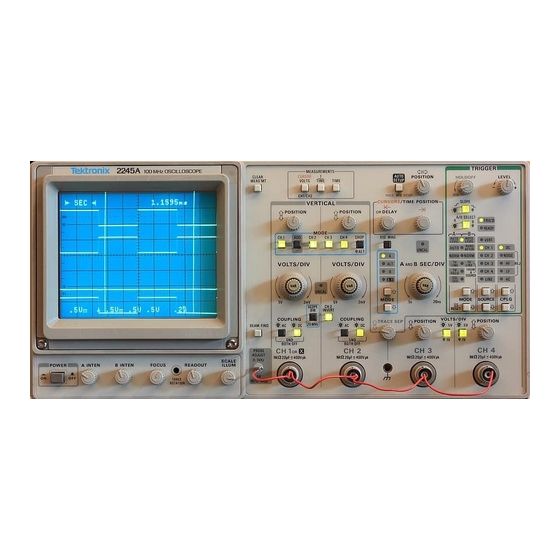
Tektronix 2245A Analog Oscilloscope Manuals
Manuals and User Guides for Tektronix 2245A Analog Oscilloscope. We have
2
Tektronix 2245A Analog Oscilloscope manuals available for free PDF download: Operator's Manual
Tektronix 2245A Operator's Manual (194 pages)
PORTABLE OSCILLOSCOPE
Brand:
Tektronix
| Category:
Test Equipment
| Size: 5 MB
Table of Contents
Table of Contents
5
List of Illustrations
10
Operators Safety Summary
12
Section 1-Introduction
17
Product Overview
17
Description
17
Standard Accessories
19
Preparation for Use
20
Safety
20
Line Fuse
20
Line Voltage and Power Cord
20
Instrument Cooling
22
Start-Up
22
Repackaging for Shipment
23
Section 2-Controls, Connectors, and Indicators
27
Crt, Power, and Display
27
Vertical
29
Horizontal
33
Behavior for Horizontal MODE Changes
34
Trigger
37
A Trigger Modes
39
B Trigger Modes
40
VERT Trigger SOURCE
42
Rear Panel
43
Measurements and Auto Setup Controls
44
Section 3-Operators Familiarization
49
Basic Operation
49
Readout Display
49
Graticule
49
Connecting Input Signals
51
Grounding
51
Coaxial C Ables
52
External Triggering
52
Probes
52
Auto Setup
53
Min Setup
53
Measurement System
53
Cursor Volts Measurements
53
Time Measurements
54
Behavior for Horizontal Mode Changes
55
Measurement Compatibility and Error Messages
56
Measurements in Single Sequence Mode
56
Service Menu Features
57
Configure Menu
58
Self Cal Measurements
59
Internal Settings Menu
60
Section 4-Operator Checks and Adjustments
63
Introduction
63
Initial Setup
63
Auto Setup Function
64
Trace Rotation Adjustment
65
Probe Low-Frequency Compensation
65
Vertical Deflection Check
67
Timing Checks
68
Section 5-Basic Applications
71
Introduction
71
Voltage Measurement Cursors
71
Voltage Difference
71
Time Measurement Cursors
73
Time D Ifference
73
Period M Easurem Ent
74
Frequency Measurement
75
Rise-Time Measurements
76
Phase Measurements
78
Time Delay Measurement
81
Add Mode
84
Section 6-Performance Characteristics
89
Introduction
89
Recommended Calibration Schedule
89
Electrical C Haracteristics
89
Environmental Characteristics
101
Mechanical Characteristics
103
Section 7-Performance Check Procedure
111
Introduction
111
Test Equipment Required
111
Performance Check Interval
111
Preparation
111
Test Equipment Required
113
Performance Check Procedure
116
Index to Performance Check Procedure
116
D Is P L a y
118
Display
118
Trace Rotation
118
Geometry
119
Vertical
120
Input COUPLING Functional Check
120
1 And CH 2 VOLTS/DIV Trace S H Ift
121
1 And CH 2 VOLTS/DIV Trace Shift
121
1 And CH 2 VAR VOLTS/DIV Trace Shift
122
3 And CH 4 VOLTS/DIV Trace S H Ift
122
3 And CH 4 VOLTS/DIV Trace Shift
122
1 And CH 2 Input COUPLING Trace Shift
123
1 And CH 2 VAR VOLTS/DIV Range
123
2 INVERT Trace S H Ift
123
2 INVERT Trace Shift
123
Low Frequency L in E a Rity
124
Low-Frequency Linearity
124
1 And CH 2 Vertical Deflection Accuracy
125
3 And CH 4 Vertical Deflection a C C U Ra C y
126
3 And CH 4 Vertical Deflection Accuracy
126
ADD Mode and CH 2 INVERT Deflection Accuracy
127
Vertical POSITION Range (All Channels)
128
1 To CH 2 Signal Delay Match
129
1 To CH 4 Signal Delay Match
130
1 And CH 2 Vertical Bandwidth
131
Ch 1 and CH 2 Vertical Bandwidth
131
3 And CH 4 Vertical Bandwidth
132
SCOPE BW (Bandwidth Lim It) a Ccu Ra Cy
132
Common-Mode Rejection R a Tio
133
Common-Mode Rejection Ratio
133
Channel Isolation
134
AC-Coupled Lower -3 Db P O in T
135
AC-Coupled Lower -3 Db Point
135
BEAM FIND Functional Check
136
Vertical ALT and CHOP Mode
136
Vertical ALT and CHOP Modes
136
A and B Trace Separation
137
Triggering
138
T R Ig G E R in G
138
Hz Trigger Sensitivity
138
500 Khz Trigger Sensitivity
139
Khz Trigger Sensitivity
139
25 Mhz Trigger Sensitivity
140
Mhz Trigger Sensitivity
140
150 Mhz Trigger Sensitivity
141
Single Sweep Mode
142
Trigger LEVEL Control Range
143
TV Field Trigger Sensitivity
144
TV Line Trigger Sensitivity
144
Line Trigger Functional Check
145
Horizontal
146
A and B Sweep Length
146
Horizontal POSITION Range
147
VAR SEC/DIV Range
148
Magnifier Registration
148
A and B Timing Accuracy and Linearity
148
Settings for Timing Accuracy Checks
149
A and B Magnified Timing Accuracy and Linearity
151
Delay Time J Itte R
152
Delay Time Jitter
152
Delay Time Accuracy
153
Delay Time Position Range
154
Delay Time Position R an Ge
154
X-Axis Bandwidth
155
Measurement Cursors
156
L<- SEC ~ > L and |<- 1/SEC -"| Cursor Accuracy
156
K- VOLTS -H Cursor Accuracy
157
I<- VOLTS Cursor Accuracy
157
External Z-A Xis, Probe Adjust, and Auto Setup Func Tions
158
Check External Z-Axis Input
158
Check External Z-Axis in P U T
158
PROBE ADJUST O U Tp U T
159
AUTO SETUP Functional Check
159
Option 15
160
Signal Output
160
A GATE Output
161
Section 8-Options and Accessories
165
Introduction
165
Options A1-A5 International Power Cords
165
Option 15
165
Standard Accessories
166
Optional Accessories
167
C am Eras
167
Instrument Enhancements
167
Probes
167
Transportation Aids
167
Viewing Hoods
167
AUTO-SETUP Control S Ettings
171
M in SETUP C Ontrol S E Ttin G S 3
174
Factory Settings
175
AUTO SETUP Functional Check
185
PROBE ADJUST Output
185
Signal Output
189
Advertisement
Tektronix 2245A Operator's Manual (190 pages)
PORTABLE OSCILLOSCOPE
Brand:
Tektronix
| Category:
Test Equipment
| Size: 6 MB
Table of Contents
Table of Contents
101
Description
7
Standard Accessories
9
Preparation for Use
10
Line Fuse
10
Line Voltage and Power Cord
10
Instrument Cooling
12
Start-Up
12
Repackaging for Shipment
13
Vertical
41
Table of Contents
101
Trigger
104
Section 7-Performance Check Procedure
109
Introduction
111
Test Equipment Required
111
Performance Check Interval
111
Preparation
111
Test Equipment Required
113
Index to Performance Check Procedure/Display
116
Display
116
Trace Rotation
116
Index to Performance Check Procedure
116
Trace Rotation
118
Geometry
119
Input COUPLING Functional Check
120
Vertical
120
1 And CH 2 VOLTS/DIV Trace Shift.7-11
121
3 And CH 4 VOLTS/D!V Trace Shift
122
1 And CH 2 VAR VOLTS/DIV Trace Shift.7-12
122
1 And CH 2 VAR VOLTS/DIV Trace Shift
122
1 And CH 2 Input COUPLING Trace Shift.7-13
123
2 INVERT Trace Shift
123
1 And CH 2 VAR VOLTS/DIV Range.7-13
123
1 And CH 2 Input COUPLING Trace Shift
123
1 And CH 2 VAR VOLTS/DIV Range
123
Low-Frequency Linearity
124
Low Frequency Linearity
124
1 And CH 2 Vertical Deflection Accuracy.7-15
125
1 And CH 2 Vertical Deflection Accuracy
125
ADD Mode and CH 2 INVERT Defiection Accuracy
127
Vertical POSITION Range (All Channels).7-18
128
1 To CH 2 Signal Delay Match
129
1 To CH 4 Signal Delay Match.7-19
130
3 To CH 4 Signal Delay Match.7-20
130
1 To CH 4 Signal Delay Match
130
Ch 1 and CH 2 Vertical Bandwidth
131
Scope BW (Bandwidth Limit) Accuracy
132
3 And CH 4 Vertical Bandwidth
132
Common-Mode Rejection Ratio
133
Channel Isolation
134
AC-Coupled Lower ~3 Db Point
135
AC-Coupled Lower-3 Db Point
135
Vertical ALT and CHOP Modes
136
BEAM FIND Functional Check
136
A and B Trace Separation
137
A and B T Race Separation
137
Triggering
138
500 Hz Trigger Sensitivity
138
Hz Trigger Sensitivity
138
Khz Trigger Sensitivity
139
Mhz Trigger Sensitivity.7-30
140
Mhz Trigger Sensitivity.7-31
141
Single Sweep Mode
142
Trigger LEVEL Control Range
143
TV Field Trigger Sensitivity.7-34
144
TV Line Trigger Sensitivity
144
Line Trigger Functional Check
145
Horizontal
146
A and B Sweep Length
146
Horizontal POSITION Range
147
Magnifier Registration
148
A and B Timing Accuracy and Linearity
148
Settings for Timing Accuracy Checks
149
A and B Magnified Timing Accuracy and Linearity
151
Delay Time Jitter
152
Delay Time Accuracy
153
X-Axis Gain Accuracy.7-44
154
Delay Time Position Range.7-44
154
X-Y Phase Difference
155
X-Axis Bandwidth
155
Measurement Cursors
156
SEC ->L and 1/SEC -M Cursor Accuracy
156
VOLTS ->I Cursor Accuracy
157
External Z-Axis, Probe Adjust and Auto Setup Functions
158
PROBE ADJUST Output
159
AUTO SETUP Functional Check.7-49
159
Signal Output
160
A GATE Output
161
Section 8-Options and Accessories
163
Introduction
165
Options A1-A5 International Power Cords.8-1
165
Standard Accessories
166
Optional Accessories
167
Instrument Enhancements
167
Transportation Aids.8-2
167
Cameras.8-2
167
Probes.8-3
167
Viewing Hoods
167
AUTO-SETUP Control Settings
171
MIN SETUP Control Settings
174
Factory Settings
175
Advertisement
Related Products
Tektronix 2246 1Y
Tektronix 2246 2R
Tektronix 2246 MOD A
Tektronix 2247A
Tektronix 2246 A
Tektronix 2246
Tektronix 2245
Tektronix 2213A
Tektronix 2236A
Tektronix 2215
Tektronix Categories
Test Equipment
Measuring Instruments
Amplifier
Portable Generator
Printer
More Tektronix Manuals
Login
Sign In
OR
Sign in with Facebook
Sign in with Google
Upload manual
Upload from disk
Upload from URL