
Subscribe to Our Youtube Channel
Related Manuals for BONFIGLIOLI TECNOINGRANAGGI LC Series


Summary of Contents for BONFIGLIOLI TECNOINGRANAGGI LC Series
- Page 1 Manuale installazione uso e manutenzione Installation, use and service manual Benutzerhandbuch Manuel d'installation et d'entretien Manual instalación uso y mantenimiento...
-
Page 3: Table Of Contents
SOMMARIO Capitolo Descrizione INFORMAZIONI GERERALI ..........2 SCOPO DEL MANUALE. -
Page 4: Informazioni Gererali
1 INFORMAZIONI GERERALI 1.1 SCOPO DEL MANUALE Questo manuale è stato realizzato dal Costruttore per fornire le informazioni necessarie a coloro che, relativamente al riduttore, sono autorizzati a svolgere in sicurezza le attività di trasporto, movimentazione, installazione, manutenzione, riparazione, smontaggio e smaltimento. Tutte le informazioni necessarie agli acquirenti ed ai progettisti, sono riportate nel “... -
Page 5: Identificazione Dell'apparecchiatura
1.2 IDENTIFICAZIONE DELL’APPARECCHIATURA La targhetta di identificazione raffigurata è applicata sul riduttore. In essa sono riportati i riferimenti e tutte le indicazioni indispensabili alla sicurezza di esercizio. Per interpretare il codice identificativo del riduttore consultare il catalogo di vendita. Se il riduttore è completo di motore elettrico (motoriduttore), le informazioni riguardanti il motore sono reperibili nel manuale corrispondente. -
Page 6: Informazioni Tecniche
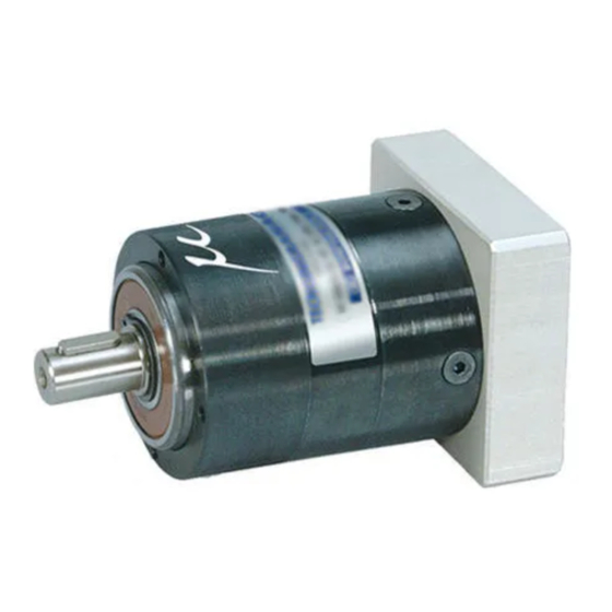
2 INFORMAZIONI TECNICHE 2.1 DESCRIZIONE RIDUTTORE Il riduttore epicicloidale a gioco ridotto, tipo LC, è realizzato unicamente nella forma coassiale e con predisposizione flangiata per il montaggio diretto del motore. Maggiore dettaglio sul prodotto può essere reperito sul relativo catalogo di vendita. 2.2 CONFORMITÀ... -
Page 7: Movimentazione E Trasporto
4 MOVIMENTAZIONE E TRASPORTO 4.1 SPECIFICHE DEGLI IMBALLI L’imballo standard, quando fornito e se non diversamente concordato, non è impermeabilizzato contro la pioggia ed è previsto per destinazioni via terra e non via mare e per ambienti al coperto e non umidi. Il materiale, opportunamente conservato, può... -
Page 8: Montaggio Del Motore Elettrico
5.2 MONTAGGIO DEL MOTORE ELETTRICO 1. Orientare l’ albero del motore in modo che la sede della chiavetta si disponga in corrispondenza dell’intaglio del morsetto calettatore. 2. Accoppiare le flange di motore e riduttore fino a portarle perfettamente a battuta. Non applicare spinte eccessive. - Page 9 Coppia Coppia Coppia di albero Vite trasmessa trasmessa serraggio motore morsetto con 20°C con 90°C [Nm] [Nm] [Nm] 6 / 6.35 9 / 9.52 12 / 12.7 12 / 12.7 15 / 15.875 5. Re-inserire il tappo di chiusura nel foro della flangia di adattamento.
-
Page 10: Montaggio Del Riduttore Sulla Macchina
6 MONTAGGIO DEL RIDUTTORE SULLA MACCHINA Sulla superficie anteriore del riduttore sono ricavati n° 4 fori filettati per il fissaggio del riduttore alla macchina comandata. Prima dell’inserimento delle viti, applicare su queste una piccola quantità di prodotto anti- svitamento, ad esempio Loctite 243. Attenersi al tipo di vite e alle relative coppie di serraggio specificate nella tabella seguente: coppia di classe di... -
Page 11: Uso Dell'apparecchiatura
8 USO DELL’APPARECCHIATURA Prima di mettere in funzione il riduttore, è necessario verificare che l’impianto in cui esso è inserito sia conforme a tutte le direttive vigenti, in particolare quelle relative alla sicurezza e salute delle persone nei posti di lavoro. Il riduttore non deve essere impiegato in ambienti e zone: Con vapori, fumi o polveri altamente corrosivi e/o abrasivi. -
Page 12: Lubrificazione
Pulire il riduttore dalla polvere e dagli eventuali residui di lavorazione. Non usare solventi o altri prodotti non compatibili con i materiali di costruzione e non dirigere sul riduttore getti d’acqua ad alta pressione. 9.3 LUBRIFICAZIONE I riduttori sono riempiti in fabbrica con carica di lubrificante idoneo per il funzionamento in qualsiasi posizione di montaggio. - Page 13 INDICE DI REVISIONE DOCUMENTO SEZIONE DESCRIZIONE...
- Page 15 SUMMARY Chapter Description GENERAL INFORMATION ..........14 PURPOSE OF THE MANUAL .
-
Page 16: General Information
1 GENERAL INFORMATION 1.1 PURPOSE OF THE MANUAL This manual has been compiled by the Manufacturer to provide information on the safe transport, handling, installation, maintenance, repair, disassembly and dismantling of the gear units. All purchasing and design criteria is provided in the Sales Catalogue. Apart from adhering to established engineering practices, the information given in this manual must be carefully read and applied rigorously. -
Page 17: Equipment Identification
1.2 EQUIPMENT IDENTIFICATION The gear unit bears the following nameplate. The nameplate bears all references and indispensable safety instructions. The gear unit’s identifying code is explained in the Sales Catalogue. If the gear unit is supplied complete with electric motor (gearmotor), all information regarding the motor itself is supplied in the motor manual. -
Page 18: Technical Information
2 TECHNICAL INFORMATION 2.1 DESCRIPTION OF THE GEARBOX Planetary gearboxes with reduced backlash Series LC are only available in the in- line design with input flange for direct motor mounting. Detail product information can be found on the sales catalogue. 2.2 COMPLIANCE TO NORMS As per the definition given in the Machine Directive 98/37 CE the gearbox is not classified as a “machine”... -
Page 19: Handling And Transport
4 HANDLING AND TRANSPORT 4.1 PACKAGING The standard packaging, when supplied and unless otherwise agreed, is not proofed against rainfall and is intended for shipping by ground and not sea, and for environments which are under cover and not humid. The material can be stored in suitable conditions for a period of two years under cover at a temperature between –15 °C and +50 °... -
Page 20: Fitting The Electric Motor
5.2 FITTING THE ELECTRIC MOTOR 1. Align the key seat of motor shaft with the slit of the input coupling. 2. Match motor and gearbox until the respective flanges mate perfectly one against the other. Do not thrust excessively. WARNING Excessive forces applied on the motor may result into damages on the gear unit or the motor itself. - Page 21 Torque Torque Motor Tightening Locking transmitted transmitted shaft torque bolt at 20°C at 90°C diam. [Nm] [Nm] [Nm] 6 / 6.35 9 / 9.52 12 / 12.7 12 / 12.7 15 / 15.875 5. Restore the plug blanking the hole of the motor adapter into its seat.
-
Page 22: Installation Of The Gearbox Onto The Machine
6 INSTALLATION OF THE GEARBOX ONTO THE MACHINE The front flange of the gearbox features 4 nos. tapped holes that allow the unit to be fixed to the driven machine. Prior to inserting the mounting bolts apply a small quantity of product, type Loctite 243 or similar, preventing the bolts from coming loose. -
Page 23: Using The Equipment
8 USING THE EQUIPMENT Before putting the gear unit into service, the User must ensure that the plant in which it is installed complies with all applicable directives, especially those regarding health and safety at work. The gear unit may not be used in areas and environments: with highly corrosive and/or abrasive vapours, smoke or dust in direct contact with loose food products. -
Page 24: Lubrication
9.3 LUBRICATION Gearboxes are filled at the factory with synthetic lubricant in a quantity suitable for operation in any mounting position. In the absence of contamination the original lubricant charge can be considered “ for life” and no periodical changes are required. Lubricant specs can be found on the nameplate. - Page 25 INDEX OF REVISIONS DOCUMENT SECTION DESCRIPTION...
- Page 27 ZUSAMMENFASSUNG Kapitel Beschreibung ALLGEMEINE INFORMATIONEN ........26 ABSICHT DIESES HANDBUCHS.
-
Page 28: Allgemeine Informationen
1 ALLGEMEINE INFORMATIONEN 1.1 ABSICHT DIESES HANDBUCHS Das vorliegende Handbuch wurde vom Hersteller des Gerä ts erstellt, um Informationen zur sicheren Handhabung an die Personen weiterzugeben, die dazu berechtigt sind, alle mit dem Transport, dem Bewegen, der Installation, der Wartung, der Reparatur, der Demontage und der Entsorgung des Getriebes zusammenhängenden Arbeitsschritte durchzuführen. -
Page 29: Kennzeichnung Des Geräts
1.2 KENNZEICHNUNG DES GERÄTS Das hier dargestellte Maschinenschild befindet sich am Getriebe. Es zeigt alle Bezugsdaten sowie die für Betriebssicherheit unerlässlichen Angaben. näheren Angaben bezü glich Identifikationscodes des Getriebes beziehen Sie sich bitte auf den Verkaufskatalog. Bei Getrieben mit Elektromotor (Getriebemotor), finden sich die den Motor betreffenden Informationen im entsprechenden Handbuch. -
Page 30: Technische Informationen
2 TECHNISCHE INFORMATIONEN 2.1 BESCHREIBUNG DES GETRIEBES Das spielarme Planetengetriebe des Typs LC wird ausschließlich in Koaxialform und mit Flanschenansatz für die Direktmontage des Motors hergestellt. Weitere Produktdetails finden Sie im jeweiligen Verkaufskatalog. 2.2 RICHTLINIENKONFORMITÄT Gemäß der Maschinenrichtlinie 98/37 CE wird ein Untersetzungsgetriebe nicht als „Maschine“ eingestuft sondern als Komponente hergestellt, die ggf. -
Page 31: Lagerung
Räumen bei einer Temperatur zwischen -15°C und +50°C und einem Feuchtigkeitsgrad nicht ü ber 80% gelagert werden. Bei anderen Umgebungsbedingungen muss eine Sonderverpackung benutzt werden. Bei der Anlieferung des Getriebes sicherstellen, dass die beim Kauf vereinbarten Merkmale gegeben sind und dass keine Schäden oder Störungen vorliegen. Eventuelle Betriebsfehler beim TECNOINGRANAGGI-RIDUTTORI-Verkäufer anzeigen. -
Page 32: Montage Des Elektromotors
5.2 MONTAGE DES ELEKTROMOTORS 1. Drehen Sie die Motorwelle so, dass der Sitz der Passfeder mit der Kerbe der Schrumpfscheibe übereinstimmt. 2. Passen Sie die Flansche von Motor und Getriebe aneinander an, bis sie sauber aufeinander liegen. Vermeiden Sie zu kräftige Stöße. WARNUNG Übermäßig hohe Kräfte, die auf den Motor wirken, können Beschädigungen am Getriebe oder am Motor selbst verursachen. - Page 33 angegebene Anzugsmoment fest: Bei 20 °C Bei 90 °C Schrumpf- Anzugsmoment übertragenes übertragenes scheiben- Antriebswelle [Nm] Drehmoment Drehmoment schraube [Nm] [Nm] 6 / 6.35 9 / 9.52 12 / 12.7 12 / 12.7 15 / 15.875 5. Den Verschlussstopfen wieder in die Bohrung des Anpassungsflansches montieren.
-
Page 34: Installation Des Getriebes In Die Maschine
6 INSTALLATION DES GETRIEBES IN DIE MASCHINE Auf der Getriebevorderseite befinden sich vier Gewindebohrungen, mit deren Hilfe das Getriebe an der entsprechenden Maschine befestigt werden kann. Auf die Schrauben vor dem Eindrehen eine dü nne Schicht Gewindehaftmittel auftragen, z.B. Loctite 243. Bitte entnehmen Sie den Schraubentyp und das dazugehörige Anzugsmoment der nachstehenden Tabelle. -
Page 35: Einsatz Des Geräts
8 EINSATZ DES GERÄTS Bevor das Getriebe gestartet wird, muss überprü ft werden, dass die Anlage, in die es eingebaut wurde, allen geltenden Richtlinien entspricht, besonders denjenigen, die die Sicherheit und die Unversehrtheit des Personals am Arbeitsplatz betreffen. Das Getriebe darf in folgenden Umgebungen und Bereichen nicht installiert werden: In Gegenwart von hochkorrosiven und/oder zu Reibung fü... -
Page 36: Schmierung
Sicherstellen, dass kein Schmierstoff aus den Dichtungen. Überprü fen Sie das Anzugsmoment der Verschlussschraube der Schrumpfscheibe. Entnehmen Sie die entsprechenden Werte bitte der Tabelle in dieser Betriebsanleitung. Überprü fen Sie das Anzugsmoment der Verbindungsschrauben der Maschine. Entnehmen Sie die entsprechenden Werte bitte der Tabelle in dieser Betriebsanleitung. Staub und eventuelle Materialreste der Bearbeitung vom Getriebe entfernen. - Page 37 INDEX VON NEUAUSGABEN DOCUMENT ABSCHNITT BESCHREIBUNG...
- Page 39 SOMMAIRE Paragraphe Description GENERALITES ........... . . 38 BUT DU MANUEL.
-
Page 40: Generalites
1 GENERALITES 1.1 BUT DU MANUEL Ce manuel a été rédigé par le constructeur pour fournir tout conseil utile aux personnes qui devront s’occuper du réducteur, en particulier pour mener en toute sécurité toute activité de transport, manutention, installation, entretien, réparation, démontage et mise au rebut. Tous les renseignements nécessaires aux acheteurs et aux concepteurs sont indiqué... -
Page 41: Identification De L'appareil
1.2 IDENTIFICATION DE L’APPAREIL La plaquette d’identification illustrée est appliquée au réducteur. Elle contient les donné es et toutes les indications indispensables pour la sécurité durant le fonctionnement. Consulter le catalogue de vente pour interpréter le code d’identification du réducteur. Si le réducteur est livré... -
Page 42: Informations Techniques
2 INFORMATIONS TECHNIQUES 2.1 DESCRIPTION DU REDUCTEUR Le réducteur épicycloïdal à jeu réduit, type LC, est réalisé uniquement dans la forme coaxiale et avec prédisposition à bride pour le montage direct du moteur. Des informations plus détaillées sur le produit sont fournies sur le catalogue de vente. 2.2 CONFORMITE AUX NORMES Selon la Directive Machines 98/37 CE, le réducteur de vitesse n’est pas classifié... -
Page 43: Manutention Et Transport
4 MANUTENTION ET TRANSPORT 4.1 SPECIFICATIONS DES EMBALLAGES Si l’appareil est livré emballé et qu’aucune spécification particulière n’a pas été demandée, l’ emballage n’est pas résistant à la pluie ; de plus, il est conç u pour le transport terrestre et non pas maritime, ainsi que pour des locaux couverts et non humides. -
Page 44: Montage Du Moteur Electrique
5.2 MONTAGE DU MOTEUR ELECTRIQUE 1. Disposer l’arbre du moteur de façon à ce que le logement de la clavette vienne se trouver en correspondance du découpage de la frette de serrage. 2. Accoupler les brides de moteur et réducteur jusqu’à les mettre parfaitement en contact. Ne pas exercer des pressions excessives. - Page 45 serrer la vis de fermeture de la frette de serrage au couple indiqué dans le tableau suivant: Couple Couple Vis frette Couple de arbre transmise transmise serrage moteur à 20°C à 90°C serrage [Nm] [Nm] [Nm] 6 / 6.35 9 / 9.52 12 / 12.7 12 / 12.7 15 / 15.875...
-
Page 46: Montage Du Reducteur Sur La Machine
6 MONTAGE DU REDUCTEUR SUR LA MACHINE Sur la surface antérieure du réducteur sont présents 4 trous taraudés pour la fixation du réducteur à la machine commandée. Avant l’introduction des vis, appliquer sur celles-ci une petite quantité de produit anti-dé vissage, par exemple Loctite 243. Respecter le type de vis et les couples respectifs de serrage indiqués dans le tableau suivant: classe de couple de... -
Page 47: Utilisation De L'appareil
8 UTILISATION DE L’APPAREIL Avant de mettre en marche le réducteur, vérifier que l’installation sur laquelle il est monté soit conforme à toutes les directives en vigueur, en particulier aux directives relatives à la sécurité et à la santé des personnes sur le poste de travail. Le réducteur ne doit pas être employé... -
Page 48: Lubrification
Vérifier le couple de serrage de la vis de liaison à la machine. Faire réfé rence aux couples de serrage indiqués dans ce manuel. Nettoyer le réducteur en ôtant toute trace de poussière et les éventuels dé chets de travail. Ne jamais utiliser de solvants ou autres produits non compatibles avec les maté... - Page 49 INDEX DES RÉVISIONS DOCUMENT SECTION DESCRIPTION...
- Page 51 RESUMEN Párrafo Descripción INFORMACIONES GENERALES ........50 OBJETIVO DEL MANUAL .
-
Page 52: Informaciones Generales
1 INFORMACIONES GENERALES 1.1 OBJETIVO DEL MANUAL El presente manual ha sido elaborado por el fabricante para suministrar la informació n necesaria a quienes, con relación al reductor, estén autorizadas a desarrollar con seguridad las actividades de transporte, manipulación, instalación, mantenimiento, reparación, desmontaje y pintado. Todas las informaciones necesarias para los compradores y proyectistas, está... -
Page 53: Identificación De Los Grupos
1.2 IDENTIFICACIÓN DE LOS GRUPOS La placa de características gravada está fijada en el reductor. En ella se indican las referencias y todas las indicaciones indispensables para la seguridad del trabajo. Para interpretar el có digo que identifica al reductor consultar el catálogo de venta. Si el reductor lleva montado un motor elé... -
Page 54: Informaciones Técnicas
2 INFORMACIONES TÉCNICAS 2.1 DESCRIPCIÓN DEL REDUCTOR El reductor epicicloidal de juego reducido, tipo LC, solamente se construye en forma coaxial, y con predisposición embridada para el montaje directo del motor. Para mayores detalles del producto consultar el correspondiente catálogo de venta. 2.2 CONFORMIDAD NORMATIVA Según la definición de la Directiva Máquina 98/37 CE, el reductor de velocidad no está... -
Page 55: Almacenaje
en zonas cubiertas y que la temperatura esté comprendida entre -15°C y +50° C con una humedad relativa no superior al 80%. Para condiciones ambientales distintas, debe disponerse de un embalaje específico. A la recepción del reductor, asegurarse que éste corresponde a la especificació n de la compra y que no presenta daños ni anomalí... -
Page 56: Montaje Del Motor Eléctrico
5.2 MONTAJE DEL MOTOR ELÉCTRICO 1. Orientar el eje del motor de forma que el alojamiento de la chaveta coincida con la entalladura del aro cónico de apriete 2. Acoplar las bridas del motor y del reductor hasta lograr su perfecto apriete. No ejercer una fuerza excesiva. - Page 57 Tornillo Par de Ø eje transmisible transmisible apriete motor a 20°C a 90°C casquillo [Nm] [Nm] [Nm] 6 / 6.35 9 / 9.52 12 / 12.7 12 / 12.7 15 / 15.875 5. Reponer el tapón de cierre en el taladro de la brida de adaptación.
-
Page 58: Montaje Del Reductor En La Mäquina
6 MONTAJE DEL REDUCTOR EN LA MÄQUINA En la superficie frontal del reductor existen 4 taladros roscados para la fijació n del reductor a la máquina conducida. Antes de colocar los tornillos, aplicar sobre éstos una pequeñ a cantidad de producto de fijación de tornillos p.e. -
Page 59: Uso De Los Grupos
8 USO DE LOS GRUPOS Antes de poner en funcionamiento el reductor, es necesario verificar que en la instalació n en la que debe montarse, esté conforme a todas las directivas vigentes, en particular aquellas relativas a la seguridad y salud de las personas en el puesto de trabajo. El reductor no debe emplearse en ambientes y zonas: Con vapores, humos o polvos altamente corrosivos y/o abrasivos. -
Page 60: Lubricación
Controlar el par de apriete de los tornillos de fijación a la má quina. Para estos valores específicos consultar la tabla del presente manual. Limpiar el polvo del reductor y los eventuales residuos de fabricació n. No usar disolventes u otros productos incompatibles con los materiales de construcció... - Page 61 ÍNDICE DE REVISIONES DOCUMENTO SECCIÓN DESCRIPCIÓN...
- Page 64 w w w . t e c n o i n g r a n a g g i . i t HEADQUARTERS TECNOINGRANAGGI RIDUTTORI s.r.l. Via Davia, 5 40017 S. Giovanni in Persiceto Bologna (ITALY) Tel. (+39) 0516810680 Fax (+39) 0516810346 www.tecnoingranaggi.it info@tecnoingranaggi.it COD.
Need help?
Do you have a question about the TECNOINGRANAGGI LC Series and is the answer not in the manual?
Questions and answers