Table of Contents
Advertisement
Quick Links
Advertisement
Table of Contents

Related Manuals for BONFIGLIOLI Riduttori AS Series


Summary of Contents for BONFIGLIOLI Riduttori AS Series
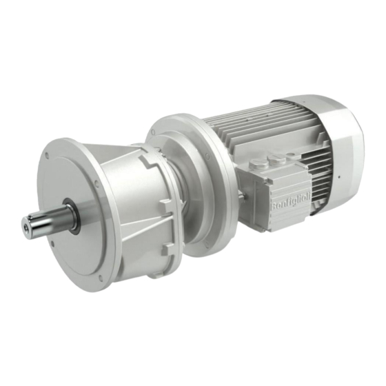
- Page 1 AS- series Installation, Operation and Maintenance Manual USER MANUAL 1/35...
-
Page 2: Table Of Contents
INSTALLATION, OPERATION AND MAINTENANCE MANUAL 1 - GENERAL INFORMATION 1.1 - PURPOSE OF THIS MANUAL 1.2 - REQUESTING TECHNICAL ASSISTANCE 1.3 - MANUFACTURER’S LIABILITY 1.4 - SUPPLEMENTARY INFORMATION 2 - SAFETY INFORMATION 2.1 - SAFETY STANDARDS 3 - TECHNICAL INFORMATION 3.1 - EQUIPMENT IDENTIFICATION 3.2 - DESCRIPTION OF THE EQUIPMENT 3.3 -CONFORMITY... -
Page 3: Installation, Operation And Maintenance Manual
This manual reflects the conditions prevalent at the time the gearbox was introduced. REQUESTING TECHNICAL ASSISTANCE For any technical service needs, contact the Manufacturer’s sales network (www.bonfiglioli.com) quoting the information indicated on the unit’s name plate, the approximate hours of service, the duty cycle and the type of defect. -
Page 4: Safety Information
2 SAFETY INFORMATION SAFETY STANDARDS Read thoroughly the instructions given in this manual and those printed directly on the gearbox, especially those regarding safety. ● Personnel appointed to work on the gearbox at any time during its service lifetime must be trained specifically for the purpose, must possess the necessary skills and experience, and must also be equipped with and trained to work with the appropriate tools and personal protection equipment required by the safety legislation applicable in the place where the gearbox/geared motor is installed. - Page 5 Unless they have backstop devices, gearboxes may reverse direction. If there is any risk of uncontrolled movement occurring in the event of a power failure (for example in load lifting applications), measures must be put in place to prevent such movement occurring (for example by using motors with brakes that engage automatically if the power fails).
-
Page 6: Technical Information
3.TECHNICAL INFORMATION 3.1 EQUIPMENT IDENTIFICATION The gearbox bears the following identifying nameplate. The nameplate provides essential information and specifications for correct and safe use. The designation of the gearbox is explained in the sales catalogue. If the gearbox is supplied fitted with a motor (geared motor), all information regarding the motor itself is provided in the motor’s own manual. -
Page 7: Description Of The Equipment
DESCRIPTION OF THE EQUIPMENT This gearbox has been designed and made for integration in an assembly of rigidly interconnected parts or mechanisms conceived to perform a specific application in which power may be provided by an electric motor. Depending on the requirements of the application, the gearbox can be supplied in a variety of versions and configurations. -
Page 8: Gear Unit Structure
GEAR UNIT STRUCTURE: 8/35... - Page 9 9/35...
-
Page 10: Operating Limits And Conditions
3.4 OPERATING LIMITS AND CONDITIONS The applications permitted by the Manufacturer are the industrial applications for which the gearbox has been designed. Changes to the gearbox version or mounting position are only permitted if previously authorized by the manufacturer’s technical assistance service. Failure to obtain this authorization invalidates the ATEX certification. -
Page 11: Allowed Temperature Limits
(*) = For further information about minimum and maximum values of different oil viscosity refer to the table “Se- lection of the optimal oil viscosity” on the catalog available on www.bonfiglioli.com (@) = Continuous operation it is not advised if t and t range is 80°C to 95 °C. -
Page 12: Storage
3.6 STORAGE Place the gearbox/ geared motor on a stable base and make sure that there is no risk of it moving or falling off. The following recommendations should be followed when storing the gearbox/geared motor. 1. Do not store the unit in excessively humid conditions or where it is exposed to the weather (i.e. outdoors). 2. -
Page 13: 4- Installation
4 INSTALLATION 4.1 INSTALLING THE GEARBOX All phases of installation and maintenance must be taken into consideration from the machine design stage. Design personnel must, if necessary, implement a safety plan to protect the health and safety of all persons directly involved and to ensure the rigorous application of all relevant legislation. - Page 14 Proceed as follows to install the gearbox. 1. Place the gearbox in the vicinity of the installation area. 2. Mount the gearbox and secure it to the structure at the fixing points provided. Secure the gearbox to the structure using all the fixing points on the relevant mounting (foot or flange). 3.
-
Page 15: Gear Boxes With Soild Shafts (Input & Output)
4.2 Gearboxes with solid shafts (input and output) Do not use hammers or other tools which might damage the gearbox shafts or bearings to fit ex- ternal parts. Proceed as shown below, following the recommendations given in the “INSTALLING CONNECTING ELEMENTS” section in this manual: Bolt (1) and spacer (2) shown above are not included in the supply. -
Page 16: Installing An Electric Motor With An Iec Standard Flange
4.3 INSTALLING AN ELECTRIC MOTOR WITH AN IEC STANDARD FLANGE 4.3.1 Thoroughly clean and degrease all the mating surfaces between the motor and the gearbox (shafts and flanges). 4.3.2 Do not force the surfaces together or use inappropriate tools to couple them. Take care not to damage the flat and/or cylindrical mating surfaces. -
Page 17: Lubrication Details
LUBRICATION DETAILS: On gearboxes with an oil level plug, check the oil level before starting up the gearbox. As with filling, this operation must be done with the gearbox in the mounting position in which it will be used in the application. If necessary, fill or top up the lubricant to the half-way point in the level window, to the reference notch on the dipstick, or until it starts to flow out of the plug hole. -
Page 18: Quantity Of Lubricant
4.5 Quantity of lubricant The quantities of lubricant specified in the tables are purely indicative. Gearboxes with level plugs correctly located for the mounting position must be filled to the mid- point of the sight glass, or to the reference notch on the dipstick, or until oil starts to flow out of the plug hole, depending on the type of level plug. -
Page 19: Gear Box Mounting Position
4.6 Gear box mounting Position: 19/35... -
Page 20: Gear Box Output Flange Mounting Details
4.7 Gear box Output flange Mounting Details: Before place the gear box on the lantern stool to be verified the spigot diameter of gear box and as well as lantern stool. According to be tolerance to be maintained for both matting parts 20/35... -
Page 21: Gear Box Input Details
4.8 Gear box Input Details: 21/35... -
Page 22: Gear Box Output Shaft Details
4.9 Gear box Output shaft details: 22/35... -
Page 23: Lantern Stool Details
4.10 Lantern stool Details: Gear box mounting Spigot diameter & lantern Stool mounting Spigot diameter / Face out to be maintained as per the values given in tabulation 2) Spigot area should not be painted. No damages, No welding Spots. Lantern stool –Run out and face out: Verify the run out and face out of lantern stool and ensure that the tolerances are within allowable limits 23/35... -
Page 24: Coupling &Accessories Details
4.11 Couplings & Accessories Details: Check shaft and coupling alignment. Run out, axial and radial misalignments, gap between couplings halves are to be maintained within limits should be periodically checked. Also check the following parameters 1. Coupling key and keyway dimensions (width, height etc.) 2. -
Page 25: Electrical Motors Details
4.14 Electrical Motor details: on Level Noise & Vibration level of Electrical motor alone should be tested before assembling with Gearbox Check the spigot diameter of motor for damages and ensure no paint on the spigot Ensure right electrical connection of motor with respect to connection (Star/Delta) 25/35... -
Page 26: Putting The Gearbox Into Service
4.15 PUTTING THE GEARBOX INTO SERVICE The gearbox has been tested in the factory by the manufacturer. Before starting it up, make sure: ● That the machine or part of the machine in which the gearbox/geared motor is to be installed has been declared to conform to the requirements of the Machinery Directive 2006/42/EC and to any other relevant and applicable safety standards. - Page 27 Measuring the gearbox surface temperature The gearbox maximum surface temperature depends on motor speed, transmission ratio and motor version, but must never exceed the value stated on the nameplate. The maximum surface temperature specified on the nameplate refers to measurements made in normal ambient and correct installation conditions.
-
Page 28: 5- Maintenance
5 MAINTENANCE Maintenance and replacement work must be carried out by expert maintenance technicians trained in the observance of applicable laws on health and safety at work and the special ambient problems attendant on the installation. In order to maintain the proper functioning and safety of the gearbox/ geared motor, we recommend that users have non-routine maintenance performed by the Manufacturer or an authorized, specialist service center. -
Page 29: Checking Operational Efficiency
Do not disperse contaminant liquids, worn parts and maintenance residues in the environment. Dispose of all such substances in strict compliance with applicable statutory legislation. • Respect scheduled inspection and maintenance intervals to ensure the correct functioning of the gearbox and the effectiveness of the explosion protection. -
Page 30: Routine Maintenance
5.2 ROUTINE MAINTENANCE Respect the manufacturer’s routine maintenance schedule to keep the gearbox at peak efficiency. Good maintenance ensures maximum gearbox performance, extended service life and continued compliance with safety regulations. Depending on the temperature reached by the lubricant, it should be replaced at the intervals indicated in the table below. - Page 31 For installations in zones 21 and 22, the user must schedule and implement a regular cleaning program for all surfaces and recesses to avoid dust build-ups of more than 5 mm in depth. Every 100 hours of operation or every 2 weeks: 5.2.1 Measure the surface temperature at the coupling between the gearbox and motor, and at the points most shielded from the forced ventilation provided by the motor’s fan.
-
Page 32: Oil Changes
OIL CHANGES 1. Place a suitable container under the drain plug. 2. Remove the filler and drain plugs and allow the oil to drain out. 3. Wait for a few minutes to ensure all the oil has drained out. Thoroughly clean the drain plug magnet (if fitted), fit a new seal and refit the drain plug. -
Page 33: Removal
6 REMOVAL REMOVING A MOTOR WITH AN IEC STANDARD FLANGE If the mobile coupling between the motor and the gearbox has not rusted badly during service, it should be possible to remove the motor without applying excessive force once the screws coupling it to the gearbox have been removed. - Page 34 7. TROUBLE SHOOTING: The following information is intended to serve as an aid in locating and eliminating defects and faults. In some cases, such problems may be caused by the plant or machine to which the gearbox is assembled and hence, the cause and remedy will be described in the Manufacturer’s technical documentation for the machine/plant in question.
- Page 35 & drive solutions to keep the world in motion. Bonfiglioli Transmissions Pvt. Ltd Survey No.528/1, Perambakkam Road Mannur Village, Sriperumbudur Taluk, Chennai – 602105 www.bonfiglioli.com TOLL FREE HELP LINE-18002743399 Log customer Service complaint to: aftersales_BTPL_PTS@bonfiglioli.com 35/35...
Need help?
Do you have a question about the Riduttori AS Series and is the answer not in the manual?
Questions and answers