RGBlink Flexpro 8 User Manual
Hide thumbs
Also See for Flexpro 8:
- User manual (65 pages) ,
- Quick start manual (50 pages) ,
- Quick start manual (46 pages)
Table of Contents
Advertisement
Quick Links
Advertisement
Table of Contents

Related Manuals for RGBlink Flexpro 8


Summary of Contents for RGBlink Flexpro 8
- Page 1 Flexpro 8 USER MANUAL Article No: RGB-RD-UM- Flexpro8 E000 Revision No: V1.0...
-
Page 2: Table Of Contents
CONTENTS CONTENTS..............................1 Declarations..............................3 FCC/Warranty............................3 Operators Safety Summary.........................4 Installation Safety Summary....................... 4 Chapter 1 Your Product..........................6 1.1 In the Box............................6 1.2 Product Overview........................... 7 1.2.1 Front Panel..........................8 1.2.2 Rear Panel..........................9 1.2.3 Dimension..........................10 Chapter 2 Install Your Product........................11 2.1 Plug in Signals.......................... - Page 3 6.2 Terms & Definitions........................63 6.3 Revision History..........................68 Felxpro 8 User Manual...
-
Page 4: Declarations
30 days after the transfer of risks. In the event of justified notice of compliant, RGBlink can repair the fault or provide a replacement at its own discretion within an appropriate period. If this measure proves to be impossible or unsuccessful, the purchaser can demand a reduction in the purchase price or cancellation of the contract. -
Page 5: Operators Safety Summary
Operators Safety Summary The general safety information in this summary is for operating personnel. Do Not Remove Covers or Panels There are no user-serviceable parts within the unit. Removal of the top cover will expose dangerous voltages. To avoid personal injury, do not remove the top cover. Do not operate the unit without the cover installed. - Page 6 Unpacking and Inspection Before opening Felxpro 8 processor shipping box, inspect it for damage. If you find any damage, notify the shipping carrier immediately for all claims adjustments. As you open the box, compare its contents against the packing slip. If you find any shortages, contact your sales representative.
-
Page 7: Chapter 1 Your Product
Chapter 1 Your Product 1.1 In the Box AC Power Network HDMI to DVI DVI Cable Cable Cord Cable Antistatic RJ11 to DB9 USB Disk SDI Cable Serial Cable Note: AC Power Cable supplied as standard according to destination market. Upgrade tool package and user manual are stored in the USB disk, please keep it. -
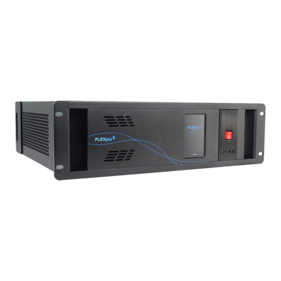
Page 8: Product Overview
Fit up to 16 independent inputs integrating a range of video sources and signals utilized in commercial display systems. The innovative RGBlink modular signal system provides native on support for HDBaseT, Fiber and LED Control signals as well as conventional signals, embracing flexibility while being an efficient self-contained system. -
Page 9: Front Panel
1.2.1 Front Panel OLED Panel Show the input shot and output slot information, device status, COM. Version, IP address and serial address. POWER Power button, long push the button, the device can be boot up. Under normal running state, push the button once, the info shown on OLED can be refreshed once ;... -
Page 10: Rear Panel
1.2.2 Rear Panel Chassis Module Structure 2 slots for input modules, support Communication DVI, HDMI and SDI optional module slots output modules, support DVI, HDMI, SDI, HDBaseT Genlock Subito Sender optional modules Independent PVW output ports PSU Module Felxpro 8 User Manual... -
Page 11: Dimension
1.2.3 Dimension Following is the dimension of Felxpro 8 for your reference: Felxpro 8 User Manual... -
Page 12: Chapter 2 Install Your Product
Chapter 2 Install Your Product 2.1 Plug in Signals Connect signals to the product (ensure all the device are all power off first).Tighten connector screws/locks where provided. 2.2 Plug in Main Power Connect IEC cable to device and plug into wall socket. Turn on power at wall socket. 2.3 Turn on Your Product Turn on the power switch on the real panel. -
Page 13: Chapter 3 Use Your Product
Chapter 3 Use Your Product 3.1 Install XPOSE 2.0 Environment Requirements: Window Processor: 1 GHz or above 32 bit or 64 bit processor Memory: 4 GB or more Graphics: Support DirectX 9 128M or above (open AERO effect) Hard disk space: Above 16G (primary partitions, NTFS format) Monitor: Resolution must be 1920x1080 pixel or above (it can not display normally if the resolution is lower than 1920x1080) Operating system: Windows 7 or above (full version, not Ghost version or compact version) - Page 14 Click “Browse...” to select the XPOSE software install location: Click “Install”: During installation, it will pop up the window of Install Shield Wizard for Virtual Com port: Felxpro 8 User Manual...
- Page 15 If user install the XPOSE software for the first time, click “Next Then click “Install", as shown in the figure below: Felxpro 8 User Manual...
- Page 16 Click “Finish” and complete the installation, as shown in the figure below: Click “Finish” and is ready to run the XPOSE : Felxpro 8 User Manual...
-
Page 17: Xpose Controls Felxpro 8
Please note that the email shall be invalid and complete otherwise registration cannot be completed. Click Activate and scan the QR code an email from ill be sent to the Register email address. RGBlink Registrations w Felxpro 8 User Manual... - Page 18 Type in the activate code and confirm, it will automatically skip to Login Keep the user name as “Admin” and password blank and then click Start Now. Note: If exact Name and Password are needed, users can set up them in Authorization Setting under System Setting.
-
Page 19: Topology Diagram
XPOSE control. 1. Drag device, input source device and output device from the list on the left based on the field application. For example, drag Flexpro 8 from Device, Laptop from Input and LDC from Output list as follows: 2. - Page 20 After one of the device is chosen, the device on the topology diagram shows the SN and IP address of the chosen one. 2.2 In and Out port will show according to the topology diagram. For example topology diagram as follow: The chosen port of board of In and Out indicated by red dot as below: Felxpro 8 User Manual...
- Page 21 3. After choosing board type, users can check the state in Input and Output 4. If there are not enough devices in the device list on the left column, users can select and load more devices to the list from the Library. Felxpro 8 User Manual...
- Page 22 Felxpro 8 User Manual...
-
Page 23: Input And Output Settings
First, choose the device from All Devices for example Flexpro 8 SN:ffff Then click icon behind Flexpro 8 in Chosen Device,IP and SN of this device is shown on the left top corner of the interface ,which indicates that the device is connected to the computer and it can be operated by XPOSE 2.0 from now on. -
Page 24: Output Setting
Output Setting 1. Click any output port, the board where the port locates is selected. Users can do settings to the port now. A red rectangle flashes around the chosen port when it is clicked. 2.1 After 2K DVI or HDMI port is selected, users can do the following settings in the edit section after clicking icon , Resolution setting, Test Pattern, DE Setting, OSD Setting. - Page 25 There are 27 standard (normal) resolution types available, the highest is 2560x816@60. If Customize is chosen, users can put in desired resolution (Width, Height, Refresh Rate) based on field application. 2.1.2 Test Pattern slide ON/OFF the Status. After slide ON the test pattern. 2.1.3 DE Setting Output Port:choose current port HDMI Output Type: DVI or HDMI...
- Page 26 Status: ON or OFF X/Y:the starting horizontal and vertical position Width/Height:the horizontal and vertical size of the text Font:font of the text,all fonts installed in the computer is available Font Type:Normal,Italic,Bold,Bold Italic Font size:0-300 pixels Pixel alignment:Left, Right, Center to Horizontal,Vertical Center Right, Align Bottom Right, Align left bottom, Vertical center left, Vertical center, Horizontal center bottom Font Transparent, Background Transparent...
-
Page 27: Input Setting
2.1 When DVI is chosen, Property, EDID Setting could be done. 2.1.1 Property Input Port:Current port Source:CVBS,YPbPr, VGA, DVI (DVI module for Flexpro 8 support for CVBS,YPbPr, VGA signal via adapter) Scale X/Y:Vertical and horizontal position Width/Height:Vertical and horizontal size... - Page 28 Contrast Red: Slide to adjust Green: Slide to adjust Blue: Slide to adjust Felxpro 8 User Manual...
- Page 29 2.1.3 EDID Setting Input Port: Current Port and type Customized EDID EDID Template : RGB-DVI and RGB-HDMI to choose White Height Frequency: automatically show current port. 2.2 When 2K HDMI port is select, users can do setting of Property and EDID 2.3When 12G SDI port is select, users can do setting of Property , DSK, LOGO and Source Merge.
- Page 30 Red,Green,Blue Max:0-255,automatically show according to user’s Preset choice Red, Green Min:0-255,automatically show according to user’s Preset choice 2.3.2 Logo Input Port:Current Port Select Logo capture or Set Logo Logo Catpure Logo ID:select from Logo1-Logo10 Slide to enable Logo capture Set Logo Logo ID: select from Logo1-Logo 10 Slide to enable Show Logo Felxpro 8...
- Page 31 2.4When USB port is selected, Property setting could be done. 2.6 Select any port is selected of 4K board (HDMI 2.0, HDMI 1.4, DP, Dual Link DVI ) There comes Property,4K Setting ,EDID Setting 2.6.1 EDID Setting Input Port Current Port and Type Customized EDID EDID Template:RGB-DVI ortRGB-HDMI Width, Height, Frequency:current...
- Page 32 2.6.2 4K Setting Input Module: current module position Operation mode: 4K x 2K, 4K x 1K, 2K x 1K, PIP 4K x 2K Input type 1: select from DVI, HDMI and DP Splice Height: no more than 2160 4K x 1K Felxpro 8 User Manual...
- Page 33 Input type 1 & Input type 2: select from DVI, HMDI and DP Splice Width 1& Splice Width 2: no more than 10000 2K x 1K Input type 1&Input type 2: select from DVI, HDMI and DP Select Main and Subsidiary picture from DVI,HDMI,DP Felxpro 8 User Manual...
-
Page 34: Device Overview
Device Overview Click Return , there are overview, IP setting,Factory Setting,Power ON,Fan Control Overview show Device Info, board info in each slot. IP:select Auto IP addres or manually type in the IP address, MASK and Gateway Factory setting:Remove Logo and/or Remove EDID Power on:0-255S Fan Control:Auto adjustment,Fan speed 0-99 Felxpro 8... - Page 35 Felxpro 8 User Manual...
-
Page 36: Display System
3.2.4 Display System Display System is for users to set layout of outputs. Click this icon first and then click enter the interface as follow: Template: There are 16 types of basic “Display Area” which is used to contain output interface,and could be regarded as layout of output. - Page 37 Mode: At present, there are Presentation Mode, PST+PGM Mode,Matrix|Aux. XPOSE 2.0 allows multiple modes running on one same interface, to differentiate each mode, different color is given to each mode. Click this icon to cancel the monitor in Display Area Long pressing this icon to cancel the Display Area Use the bar under the interface and type in the parameter to set resolution and position of...
- Page 38 Created: Click Customize below template, user can type in the width, height ,Row and Column, according to actual display in field, click .It will automatically calculate the width and height of each monitor based on the parameter above, as the following example, creat a 4000x2000 display area.
- Page 39 PST|PGM, Matrix|Aux, Parameter works the same as the bar under interface. Parameter under under the mode of Presentation, PST|PGM, Matrix|Aux mode LED cabinet Flexpro8 support to install RGBLink Subito sender designed to take direct control LED display. Led cabinet is offered to do cabinet settings. Felxpro 8...
- Page 40 Adjust Display Area Drag the boarder of the display area to move its place in the interface. Click icon to shrink,Click to enlarge the proportion of display area on interface. Felxpro 8 User Manual...
-
Page 41: Layer Management
3.2.5 Layer Management Layer Management is designed to manage the layer of each monitor. Click this icon to enter the interface: Display Area Here is to show all the Display Area set in previous step System Management. Click cancel or use the corresponding Display Area. Signal To show the signal list of 16 inputs. - Page 42 Layer Adjustment Under the Presentation Mode, there are two ways to adjust layer. 1. Use the bar under the interface Choose one layer and the bar shows its signal source, type in position and size. 2. Layer Scale or Crop Layer Movement Place the cursor on the layer, it turns to a palm icon , press the left of mouse, the icon turns...
- Page 43 Layer Remove Click the cross on the top right of the layer to remove the layer if needed. Layer Max Click this icon , to cover up all monitors in the same Display Area with the one signal, as the following: Layer Copy Press Ctrl and mouse left at the same time, move the mouse the layer selected can be copied and...
- Page 44 Layer Lock Click the lock icon on the right middle of the later boarder. When the layer is locked, any movement or removal to the layer is invalid H.264 Slide H.264 to ON Module Index: H.264 Image Quality: to choose from 1:1,1:2,1:3,1:4,1:5,1:6, the higher the ratio the better the preview input image but if band width of network is not good enough, high ratio image quality may cause problem.
- Page 45 Hot Keys Hot keys, provided to do quick layer setting such as Copy Layer, Layer move Save to Bank Automatically When one Bank (where the set is contained) is finished, click next Bank, previous set is saved to bank. Felxpro 8 User Manual...
-
Page 46: Preset Management
3.2.6 Preset Management Preset Management is designed to switch bank (scene setting done in last step). Preset Management Mode:1 Manual Mode, 2 Schedule Mode Manual Mode Fade Time 0.0-10.0S Black out, slide to ON or OFF The tick on the bank indicates that the bank is selected. Cut|Take Cut, switch from PST to PGM without any effect. - Page 47 Display separate display area switching and select the Display Area Slide Disply to ON , Click when users need to switch scene from eg. Bank 1 to Bank 2 but want to keep Display Area 2 and 3 the same as Bank 1. Follow the steps below to do the setting. Step1: click Bank 2 and open Display Area Step 2: click the icon behind to cancel the display area of 2 and 3 and click...
- Page 48 Bank Save and Load Save Bank to Page Select a bank,click Page,select Page X,the bank is saved in the page. The page turns green then become grey, indicating the bank is saved in the page. Load bank from Page Click Load Page, pages with bank saved are green, select one from them and the selected one becomes red.
- Page 49 Preset Name Select a bank and click Preset Name , fill in the blank after New Preset Name to rename a Preset (Bank) Click the color block after Color Selection and choose a new color for the boarder of chosen bank. For exmaple change Bank1to RBGLINK, with green boader Display Area is to let users to choose which display areas to display on the PGM and allow users to set...
- Page 50 Is designed to control and monitor the streaming media server such as UMS4 or VMix. Schedule Mode This mode is designed to set auto bank (scene/preset) switch. Loop Click under , select a bank and set Start Time and End Time. Click OK , the bank will be added to the loop list on the left.
- Page 51 Long pressing to remove the bank from loop list when loop is OFF (Note, Loop need to be disabled first, if a bank need to be removed from loop list) Felxpro 8 User Manual...
-
Page 52: Keyboard Setting
3.2.7 Keyboard Setting Keyboard setting is designed to fit for different operation systems such as Windows and Mac. Users can set short cut keys for Input, Output, Layer and Preset. Drag Input, Output, Layer and Preset from the list to the keys you desired as follow: Input, Output, Layer and Preset. - Page 53 Felxpro 8 User Manual...
-
Page 54: System Setting
3.2.8 System Setting Click this icon and enter the interface System Info,Software Version and Language options with English and Russia to choose. Communication Setting,this is to decide how XPOSE to communicate with the device By serial port,ethernet connection,or both are chosen Find Device:choose the devices that users need to be connected Authorization setting:type in the password and to set up subordinate user’s authorization. - Page 55 XPOSE do operation on one device, same operation synchronized to other devices. For example, there are two devices linked to the same network, one with IP IP192.168.0.112 SN 0027, the other 192.168.0.129 SN 3344 as followed: If users need to back up operation from current running device 3344 to 0027, slave unit shall be used.
-
Page 56: Chapter 4 Order Codes
Chapter 4 Order Codes 4.1 Product 710-1008-01-0 Felxpro 8 4.2 Options 4.2.1 Input Options 190-1001-09-0 Single HDBaseT Input Module-Dual Bracket 190-0001-10-2 Single USB Input and Backup Module 190-0001-07-2 Single 3G-SDI Input/ Loop Module 190-0001-13-2 Single HDMI Input Module 190-0001-04-2 Single DVI Input Module 4.2.2 Output Options 790-0001-22-0 Single HDMI Output Module... -
Page 57: Chapter 5 Support
Chapter 5 Support 5.1 Contact Us Felxpro 8 User Manual... -
Page 58: Chapter 6 Appendix
Chapter 6 Appendix 6.1 Specification Single DVI Input Module Interface Appearance Board Size 40x20mm Number of Connectors Connector DVI-I (Compatible with DVI,CVBS,YPbPr, VGA) Supported Standards Single Link DVI Supported Resolution SMPTE 480i | 576i | 720p@50/59.94/60 | 1080i@50/59.94/60 | 1080p@50/59.94/60 VESA 800×600@60 |1024×768@60 |1280×768@60 I 1280×1024@60 | 1600×1200@60 | 1920×1080@60 |... - Page 59 H264 .MKV H.264 1920 × 1080 20Mbps | .MOV MJPEG .AVI 640 × 480@3 10Mbps DivX .DIVX | .AVI MPEG | 1920 × 1080 20Mbps DVIX | H264 .WMV 1920×1080 20Mbps | .ASF .FLV H264 1920×1080 20Mbps Picture Formats File Type Max Resolution Supported Compression...
- Page 60 Interface Appearance Board Size 40(L)×38(W)(mm) Number of Connectors 2 (1 Input, 1 Loop) Connector Supported Resolution SMPTE 480i | 576i | 720p@50/60 | 1080i@59.94/60 | 1080p@23.98/24/25/29.97/30/59/59.94/60 | 1080psf@23.98/24/25/29.97/30 Supported Standard SMPTE 425M (Level A & B) | SMPTE 424M | SMPTE 292M | SMPTE 259M-C | DVB-ASI HDBaseT Input Module Interface Appearance...
- Page 61 DVI Output Module Interface Appearance Board Size 40(L)×38(W)(mm) Number of Connectors Connector Standard DVI-I Socket Supported SMPTE 720p@50/59.94/60| 1080p@50/59.94/60 Resolution VESA 800x600@60 |1024x768@60/75/85 |1280x720@50/59.94/60 |1280x800@60 |1280x960@60 | 1280x1024@60/75/85 | 1400x1050@60 |1600x1200@60 |1920x1080@23.98/24/25/29.97/30/50/59.94/60 |2048x1152@60 3G SDI Output Module Interface Appearance Board Size 40(L)×38(W)(mm)...
- Page 62 DP 1.1 Output Module Interface Apperance Board Size 40(L)×38(W)(mm) Number of Connectors Connector DisplayPort Supported SMPTE 720p50/59.94/60 | 1080i50/59.94/60 | 1080P50/59.94/60 Resolution VESA 800×600@60 | 1024×768@60 | 1280×768@60 | 1280×1024@60 | 1600×1200@60 | 1920×1080@50/60 Format Standard DP 1.1 HDBaseT Output Module Interface Appearance Number of Connectors...
- Page 63 1920×1200@60 | 2048×1152@60 | 2560×1440@60 Capacity 655,360 pixels ( each port) Horizontal Range 3840 pixels( each port) Vertical Range 2048 pixels( each port) Communication Interface Appearance Genlock Number of Connectors Connector BNC (1 In | 1 Loop) Control Number Connectors Connector 1×RJ11 |1×...
- Page 64 6.2 Terms & Definitions The following terms and definitions are used throughout this guide. “ASCII”: American Standard for Information Interchange. The standard code consisting of 7-bit coded characters (8 bits including parity check) used to exchange information between data processing systems, data communication systems, and associated equipment.
- Page 65 “Color temperature”: The color quality, expressed in degrees Kelvin(K), of a light source. The higher the color temperature, the bluer the light. The lower the temperature, the redder the light. Benchmark color temperature for the A/V industry include 5000°K, 6500°K, and 9000°K. ...
- Page 66 degree of compression can be adjusted, allowing a selectable tradeoff between storage size and image quality. JPEG typically achieves 10:1 compression with little perceptible loss in image quality. Produces blocking artifacts. “MPEG”: Motion Picture Expect Group. A standard committee under the auspices of the International Standards Organization working on algorithm standards that allow digital compression, storage and transmission of moving image information such as motion video, CD-quality audio, and control data at CD-ROM bandwidth.
- Page 67 a given color in any image is free from white. The less white in a color, the truer the color or the greater its saturation. On a display device, the color control adjusts the saturation. Not to be confused with the brightness, saturation is the amount of pigment in a color, and not the intensity.
- Page 68 “VGA”: Video Graphics Array. Introduced by IBM in 1987, VGA is an analog signal with TTL level separate horizontal and vertical sync. The video outputs to a 15-pin HD connector and has a horizontal scan frequency of 31.5 kHz and vertical frequency of 70 Hz (Mode 1, 2) and 60 Hz (Mode 3).
- Page 69 6.3 Revision History The table below lists the changes to the Video Processor User Manual. Format Time ECO# Description Principal V1.0 2019-09-01 0000# Release Fanny Felxpro 8 User Manual...
Need help?
Do you have a question about the Flexpro 8 and is the answer not in the manual?
Questions and answers