RGBlink FLEXpro 8 User Manual
Hide thumbs
Also See for FLEXpro 8:
- User manual (69 pages) ,
- Quick start manual (50 pages) ,
- Quick start manual (46 pages)
Table of Contents
Advertisement
Quick Links
Advertisement
Table of Contents

Related Manuals for RGBlink FLEXpro 8


Summary of Contents for RGBlink FLEXpro 8
- Page 1 FLEXpro 8 USER MANUAL Article No: RGB-RD-UM- Flexpro8 E000 Revision No: V1.1...
-
Page 2: Table Of Contents
CONTENTS CONTENTS..............................1 Declarations..............................2 FCC/Warranty............................2 Operators Safety Summary.........................3 Installation Safety Summary....................... 3 Chapter 1 Your Product..........................5 1.1 In the Box............................5 1.2 Product Overview........................... 6 1.2.1 Front Panel..........................7 1.2.2 Rear Panel..........................8 1.2.3 Dimension..........................9 Chapter 2 Install Your Product........................10 2.1 Plug in Signals.......................... -
Page 3: Declarations
30 days after the transfer of risks. In the event of justified notice of compliant, RGBlink can repair the fault or provide a replacement at its own discretion within an appropriate period. If this measure proves to be impossible or unsuccessful, the purchaser can demand a reduction in the purchase price or cancellation of the contract. -
Page 4: Operators Safety Summary
Operators Safety Summary The general safety information in this summary is for operating personnel. Do Not Remove Covers or Panels There are no user-serviceable parts within the unit. Removal of the top cover will expose dangerous voltages. To avoid personal injury, do not remove the top cover. Do not operate the unit without the cover installed. - Page 5 Unpacking and Inspection Before opening Felxpro 8 processor shipping box, inspect it for damage. If you find any damage, notify the shipping carrier immediately for all claims adjustments. As you open the box, compare its contents against the packing slip. If you find any shortages, contact your sales representative.
-
Page 6: Chapter 1 Your Product
Chapter 1 Your Product 1.1 In the Box AC Power Network HDMI to DVI DVI Cable Cable Cord Cable Antistatic RJ11 to DB9 USB Disk SDI Cable Serial Cable Note: AC Power Cable supplied as standard according to destination market. Upgrade tool package and user manual are stored in the USB disk, please keep it. -
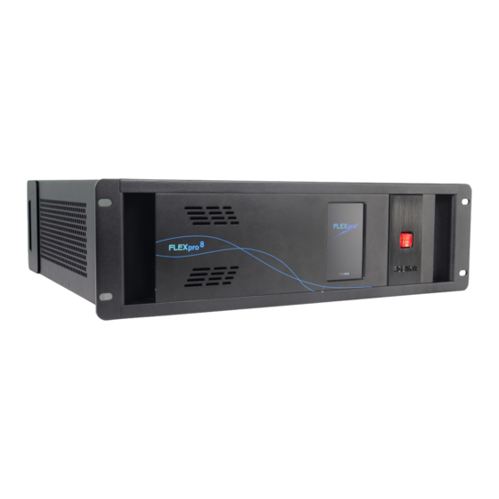
Page 7: Product Overview
Fit up to 16 independent inputs integrating a range of video sources and signals utilized in commercial display systems. The innovative RGBlink modular signal system provides native on support for HDBaseT, Fiber and LED Control signals as well as conventional signals, embracing flexibility while being an efficient self-contained system. -
Page 8: Front Panel
1.2.1 Front Panel OLED Panel Show the input shot and output slot information, device status, COM. Version, IP address and serial address. POWER Power button, long push the button, the device can be boot up. Under normal running state, push the button once, the info shown on OLED can be refreshed once ;... -
Page 9: Rear Panel
1.2.2 Rear Panel Chassis Module Structure 2 slots for input modules, support Communication DVI, HDMI and SDI optional module slots output modules, support DVI, HDMI, SDI, HDBaseT Genlock Subito Sender optional modules Independent PVW output ports PSU Module Felxpro 8 User Manual... -
Page 10: Dimension
1.2.3 Dimension Following is the dimension of Felxpro 8 for your reference: Felxpro 8 User Manual... -
Page 11: Chapter 2 Install Your Product
Chapter 2 Install Your Product 2.1 Plug in Signals Connect signals to the product (ensure all the device are all power off first).Tighten connector screws/locks where provided. 2.2 Plug in Main Power Connect IEC cable to device and plug into wall socket. Turn on power at wall socket. 2.3 Turn on Your Product Turn on the power switch on the real panel. -
Page 12: Chapter 3 Use Your Product
Chapter 3 Use Your Product 3.1 Install XPOSE 2.0 Environment Requirements: Window Processor: 1 GHz or above 32 bit or 64 bit processor Memory: 4 GB or more Graphics: Support DirectX 9 128M or above (open AERO effect) Hard disk space: Above 16G (primary partitions, NTFS format) Monitor: Resolution must be 1920x1080 pixel or above (it can not display normally if the resolution is lower than 1920x1080) Operating system: Windows 7 or above (full version, not Ghost version or compact version) - Page 13 Click “Browse...” to select the XPOSE software install location: Click “Install”: During installation, it will pop up the window of Install Shield Wizard for Virtual Com port: Felxpro 8 User Manual...
- Page 14 If user install the XPOSE software for the first time, click “Next Then click “Install", as shown in the figure below: Felxpro 8 User Manual...
- Page 15 Click “Finish” and complete the installation, as shown in the figure below: Click “Finish” and is ready to run the XPOSE : Felxpro 8 User Manual...
-
Page 16: Xpose Controls Felxpro 8
Please note that the email shall be invalid and complete otherwise Registration&Activation code cannot be received. Click Activate and scan the QR code an email from ill be sent to the Register email address. RGBlink Registrations w Type in the activate code and confirm Felxpro 8 User Manual... - Page 17 After login, users can find the management including:Topology Diagram,Search,Display System, Layer Management, Preset Management, Keyboard Settings. The details of each hierarchy will be described hereafter. In the following text, we are going to show how to use XPOSE 2.0 to control Flexpro 8. Felxpro 8 User Manual...
-
Page 18: Topology Diagram
XPOSE control. 1. Drag device, input source device and output device from the list on the left based on the field application. For example, drag Flexpro 8 from Device, Laptop from Input and LDC from Output list as follows: 2. - Page 19 After one of the device is chosen, the device on the topology diagram shows the SN and IP address of the chosen one. 4. Choose board type of In and Out according to the actual input and output modules configuration user want. For example, set the first input board as DVI module as the following Select IN|OUT: In, Model:Universal, Signal:DVI, Port:any figure from 1 to 4, click ADD finish If the input module is formed by different signal input ports, choose the Model as Typical, it will...
- Page 20 The chosen port of board of In and Out indicated by red dot as below: 5. After choosing board type, users can check the state in Input and Output and change the connection port if needed. 6. If there are not enough devices in the device list on the left column, users can select and load more devices to the list from the Library.
- Page 21 7. After topology diagram is finished, users can store the script to local hard drive so that there is no need to do topology diagram next time again. Users can upload the previously stored script if the input and output deployment is the same. Felxpro 8 User Manual...
-
Page 22: System Settings
3.2.3 System Settings Find Device New version of XPOSE 2.0 is blank default in Find Device. Users are supposed to choose the device needed in System Setting. Then click icon Click this icon and enter the interface, choose the device X14. System Info: show the current software version Language:Chinese, English and Russian Communication Setting: Search or Direct, Search default. - Page 23 Drag Input, Output, Layer and Preset from the list to the keys you desired as follow: Input, Output, Layer. Please note the keyboard area where allows to set short cut keys as follow: If the setting goes wrong or no need for short cut keys any more, click to clear some keys Felxpro 8 User Manual...
- Page 24 or clear all. Clear: is to clear some keys, the keys need to selected before hand. Clear all: is to remove all already set short cut keys. Authorization Setting to open up the authorization entry. Click Click Management New:Add new USER NAME and PASSWORD Edit: Edit user name and password already built.
-
Page 25: Output| Input | Overview
Click the green block to remove the function not to be permitted. 3.2.4 Output| Input | Overview Output Setting 1. Click any output port, the board where the port locates is selected. Users can do settings to the port now. A red rectangle flashes around the chosen port when it is clicked. - Page 26 After HBbaseT is selected, resolution setting, Test pattern and OSD setting can be done. 2.1.1 Resolution Setting Output Switch: Slide On or OFF Format Rage: Slide to select ALL or Module. (For output modules on Flexpro, there is no difference between selecting All or Module as there is only one port on each each module) Format Type:Standard or Customize.
- Page 27 2.1.4 OSD Setting: Output port: the current port Status: ON or OFF X/Y:the starting horizontal and vertical position Width/Height:the horizontal and vertical size of the text Font:font of the text,all fonts installed in the computer is available Font Type:Normal,Italic,Bold,Bold Italic Font size:0-300 pixels Pixel alignment:Left, Right, Center to Horizontal,Vertical Center Right, Align Bottom Right, Align left bottom, Vertical center left, Vertical center, Horizontal center bottom...
- Page 28 2.1 When DVI or HDMI is chosen, Property, EDID and Test Pattern could be done. 2.1.1 Property DVI port Property setting Input Port:Current port Source:CVBS,YPbPr, VGA, DVI (DVI module for Flexpro 8 support for CVBS,YPbPr, VGA signal via adapter) Scale X/Y:Vertical and horizontal position Width/Height:Vertical and horizontal size...
- Page 29 Top:crop top Width:horizontal size after crop Height:vertical size after crop Display mode:Live or Freeze Picture Adjustment Mirror:ON or OFF Alpha:transparency adjustment, range from 0~128. Mini Delay mode:On or Off. Select this mode on the output and input is simultaneously, without refresh rate delay.
- Page 30 2.1.3 EDID Setting Input Port: Current Port and type Customized EDID EDID Template : RGB-DVI and RGB-HDMI to choose White Height Frequency: automatically show current port. DVI Port EDID setting HDMI Port EDID Setting Test Pattern: Input Port:Current Port Preset: Customize,White on Black 1,White on Black 2,Black on White 1,Black on White 2,Green on Black 1,Green on Black 2,Green on White 1,Green on White 2,Red on Black 1,Red on Black 2,Red on White 1,Red on White 2 DSK Setting switch:On or Off...
- Page 31 Transparent:0-255,automatically show according to user’s Preset choice Red,Green,Blue Max:0-255,automatically show according to user’s Preset choice Red, Green Min:0-255,automatically show according to user’s Preset choice DVI Port Test Pattern HDMI Port Test Pattern SDI Port Test Pattern When USB port is selected, Property setting could be done. USB Property USB Setting Felxpro 8...
- Page 32 Input Port Current USB port Select Video or Image Choose Video, will list down the media files in video format by index. Set play loop by ,switch to previous , next and stop playing Choose Image, will list down the media files in graphic format by index. Set playing time from 0 to 255S.
- Page 33 IP:select Auto IP addres or manually type in the IP address, MASK and Gateway Fan Control:Auto adjustment,Fan speed 0-99 Power on:0-255S Factory setting:Remove Logo and/or Remove EDID Felxpro 8 User Manual...
-
Page 34: Display System
3.2.5 Display System Display System is for users to set layout of outputs. Click this icon first and then click enter the interface as follow: Template: There are 16 types of basic “Display Area” which is used to contain output interface,and could be regarded as layout of output. - Page 35 Click this icon to cancel the monitor in Display Area Long pressing this icon to cancel the Display Area Created: Click Customize below template, user can type in the total width and height , row and column , according to actual display in field, it will automatically calculate the height and wdth of each monitor based on the parameter above, as the following example, creat a 5400x1080 display area.
- Page 36 Output Show all the output ports (monitors) of this device. If the monitor is in dark (black), it indicates that this output is used, otherwise it is in grey. Display System Display System allows users to edit the name of the display area that has been created just click LED cabinet Felxpro 8 User Manual...
- Page 37 Flexpro8 support to install RGBLink Subito Quatro sender designed to take direct control LED display. Led cabinet is offered to do cabinet settings. Module Index: choose the number of the Quatro modules. Cabinet Type: Customize or Manufacture Cabinet Type: Manufacturer or Customize...
- Page 38 Use ethernet parameters to adjust position of control area. Click Ethernet then click Module to refresh Fill in the X number and Y number and set. Customize connection :Ctrl+Left Mouse Adjust Display Area Drag the boarder of the display area to move its place in the interface. Click icon to shrink,Click to enlarge the proportion of display area on interface.
-
Page 39: Layer Management
Swap Port: users can swap two monitors display Choose port from the drop down arrow list. 3.2.6 Layer Management Layer Management is designed to manage the layer of each monitor. Click this icon to enter the interface: Display Area Here is to show all the Display Area set in previous step System Management. Click to cancel or use the corresponding Display Area. - Page 40 Numbers on Monitor Numbers on monitor is to show how many layers at present allowed to put in the monitor . Each monitor (output port) can contain layers no more than 4. Any 1 input signal cross 1 border of a monitor is regarded as 2 layers. Layer Adjustment There are two ways to adjust layer.
- Page 41 Layer Movement Place the cursor on the layer, it turns to a palm icon , press the left of mouse, the icon turns to a fist , moving the mouse can drag the layer. Layer Remove Click the cross on the top right of the layer to remove the layer if needed. Layer Max Click this icon , to cover up all monitors in the same Display Area with the one signal, as the...
- Page 42 Layer Lock Click the lock icon on the right middle of the later boarder. When the layer is locked, any movement or removal to the layer is invalid Streaming Module Index:PVW, PVW port is fixed on the communication module with a dedicated HDMI port.
- Page 43 and layers in the display areas can be previewed as follow pictures. If turn on H.264 only, only input signal can be previewed. Blending Signal: current chosen signal Layer Order:Current chosen layer Width: set blending width here Blending: turn ON and OFF Blending feature. Felxpro 8 User Manual...
-
Page 44: Preset Management
Input Port:Current Port Preset: Customize,White on Black 1,White on Black 2,Black on White 1,Black on White 2,Green on Black 1,Green on Black 2,Green on White 1,Green on White 2,Red on Black 1,Red on Black 2,Red on White 1,Red on White 2 DSK Setting switch:On or Off Operation Mode:0 or 1,automatically show according to user’s Preset choice Transparent:0-255,automatically show according to user’s Preset choice... - Page 45 Manual Mode Switch Manual Mode or Schedule Module by the bar in the left bottom corner of the window. Take Setting Fade Time 0.0-10.0S Black out, slide to ON or OFF The tick on the bank indicates that the bank is selected. Cut|Take Cut, switch from PST to PGM without any effect.
- Page 46 Display separate display area switching to see more settings and select the Display Area Slide Disply to ON , click when users need to switch scene from eg. Bank 1 to Bank 4 but want to keep Display Area 2 the same as Bank 1.
- Page 47 Keep|Swap Only when separate Display switching is OFF can Keep|Swap work. Under the Keep status, users need to select a bank and use Cut or Take to switch image from PST to PGM. Under Swap status, users select a bank, then use Take or Cut to swap this bank and the bank before this one.
- Page 48 Select a bank and click Preset Name , fill in the blank after New Preset Name to rename a Preset (Bank) Click the color block after Color Selection and choose a new color for the boarder of chosen bank. For exmaple change Bank1to RBGLINK, with pointed boader Schedule Mode This mode is designed to set auto bank (scene/preset) switch.
- Page 49 Click this icon to delete this preset if it is not needed. Turn on Daily Loop and Loop Switch. Felxpro 8 User Manual...
-
Page 50: Chapter 4 Order Codes
Chapter 4 Order Codes 4.1 Product 710-1008-02-0 Felxpro 8 4.2 Options 4.2.1 Input Options 190-1001-09-0 Single HDBaseT Input Module-Dual Bracket 190-0001-10-2 Single USB Input and Backup Module 190-0001-07-2 Single 3G-SDI Input/ Loop Module 190-0001-13-2 Single HDMI Input Module 190-0001-04-2 Single DVI Input Module 4.2.2 Output Options 790-0001-22-0 Single HDMI Output Module... -
Page 51: Chapter 5 Support
Chapter 5 Support 5.1 Contact Us Felxpro 8 User Manual... -
Page 52: Chapter 6 Appendix
Chapter 6 Appendix 6.1 Specification Single DVI Input Module Interface Appearance Board Size 40x20mm Number of Connectors Connector DVI-I (Compatible with DVI,CVBS,YPbPr, VGA) Supported Standards Single Link DVI Supported Resolution SMPTE 480i | 576i | 720p@50/59.94/60 | 1080i@50/59.94/60 | 1080p@50/59.94/60 VESA 800×600@60 |1024×768@60 |1280×768@60 I 1280×1024@60 | 1600×1200@60 | 1920×1080@60 |... - Page 53 H264 .MKV H.264 1920 × 1080 20Mbps | .MOV MJPEG .AVI 640 × 480@3 10Mbps DivX .DIVX | .AVI MPEG | 1920 × 1080 20Mbps DVIX | H264 .WMV 1920×1080 20Mbps | .ASF .FLV H264 1920×1080 20Mbps Picture Formats File Type Max Resolution Supported Compression...
- Page 54 Interface Appearance Board Size 40(L)×38(W)(mm) Number of Connectors 2 (1 Input, 1 Loop) Connector Supported Resolution SMPTE 480i | 576i | 720p@50/60 | 1080i@59.94/60 | 1080p@23.98/24/25/29.97/30/59/59.94/60 | 1080psf@23.98/24/25/29.97/30 Supported Standard SMPTE 425M (Level A & B) | SMPTE 424M | SMPTE 292M | SMPTE 259M-C | DVB-ASI HDBaseT Input Module Interface Appearance...
- Page 55 DVI Output Module Interface Appearance Board Size 40(L)×38(W)(mm) Number of Connectors Connector Standard DVI-I Socket Supported SMPTE 720p@50/59.94/60| 1080p@50/59.94/60 Resolution VESA 800x600@60 |1024x768@60/75/85 |1280x720@50/59.94/60 |1280x800@60 |1280x960@60 | 1280x1024@60/75/85 | 1400x1050@60 |1600x1200@60 |1920x1080@23.98/24/25/29.97/30/50/59.94/60 |2048x1152@60 3G SDI Output Module Interface Appearance Board Size 40(L)×38(W)(mm)...
- Page 56 DP 1.1 Output Module Interface Apperance Board Size 40(L)×38(W)(mm) Number of Connectors Connector DisplayPort Supported SMPTE 720p50/59.94/60 | 1080i50/59.94/60 | 1080P50/59.94/60 Resolution VESA 800×600@60 | 1024×768@60 | 1280×768@60 | 1280×1024@60 | 1600×1200@60 | 1920×1080@50/60 Format Standard DP 1.1 HDBaseT Output Module Interface Appearance Number of Connectors...
- Page 57 1920×1200@60 | 2048×1152@60 | 2560×1440@60 Capacity 655,360 pixels ( each port) Horizontal Range 3840 pixels( each port) Vertical Range 2048 pixels( each port) Communication Interface Appearance Genlock Number of Connectors Connector BNC (1 In | 1 Loop) Control Number Connectors Connector 1×RJ11 |1×...
-
Page 58: Terms & Definitions
6.2 Terms & Definitions ●RCA:Connector used primarily in consumer AV equipment for both audio and video. The RCA connector was developed by the Radio Corporation of America. ●BNC: Stands for Bayonet Neill-Concelman. A cable connector used extensively in television (named for its inventors). - Page 59 ●HDMI : High Definition Multimedia Interface: An interface used for the transmission of uncompressed high definition video, up to 8 channels of audio, and control signals, over a single cable. ●HDMI 1.3: released on June 22 2006, and increased the maximum TMDS clock to 340 MHz (10.2 Gbit/s).
- Page 60 fibers are used for most communication links longer than 1,000 meters (3,300 ft). ●SFP:small form-factor pluggable , is a compact, hot-pluggable network interface module used for both telecommunication and data communications applications. ●optical fiber connector: terminates the end of an optical fiber, and enables quicker connection and disconnection than splicing.
- Page 61 USB 3.0 3.1&3.2 ●NTSC : The colour video standard used in North America and some other parts of the world created by the National Television Standards Committee in the 1950s. NTSC utilizes an interlaced video signals. ●PAL: Phase Alternate Line. A television standard in which the phase of the colour carrier is alternated from line to line.
- Page 62 ●NDI: Network Device interface (NDI) is a software standard developed by NewTek to enable video-compatible products to communicate, deliver,and receive broadcast quality video in a high quality, low latency manner that is frame-accurate and suitable for switching in a live production environment over TCP (UDP) Ethernet based networks.
- Page 63 ●OSC: The principle of Open Sound Control (OSC) protocol is for networking sound synthesizers, computers, and multimedia devices for musical performance or show control. As with XML and JSON, the OSC protocol allows sharing data. OSC is transported via UDP packets between devices connected on an Ethernet.
- Page 64 bars are two rows of reversed colour bars ●Seamless Switching: A feature found on many video switchers. This feature causes the switcher to wait until the vertical interval to switch. This avoids a glitch (temporary scrambling) which often is seen when switching between sources. ●Scaling: A conversion of a video or computer graphic signal from a starting resolution to a new resolution.
-
Page 65: Revision History
6.3 Revision History The table below lists the changes to the Video Processor User Manual. Format Time ECO# Description Principal V1.0 2019-09-01 0000# Release Fanny V1.1 2020-3-26 0001# Revise XPOSE operation Fanny Felxpro 8 User Manual...
Need help?
Do you have a question about the FLEXpro 8 and is the answer not in the manual?
Questions and answers