Table of Contents
Advertisement
Quick Links
Advertisement
Table of Contents

Subscribe to Our Youtube Channel
Related Manuals for Westermo Lynx 5500 Series


Summary of Contents for Westermo Lynx 5500 Series
- Page 1 Lynx 5500 Series Industrial Gigabit switch WeOS...
-
Page 2: Table Of Contents
4.2. Removal of Product ............. 17 4.3. Earth Connection ..............18 4.4. Cooling ................18 5. Specifications ................19 5.1. Interface Specifications ............19 5.2. Type Tests and Environmental Conditions ......... 22 6. Revision Notes ................27 Lynx 5500 Series... -
Page 3: General Information
Westermo reserves the right to revise this document or withdraw it at any time without prior notice. Under no circumstances shall Westermo be responsible for any loss of data or income or any special, incidental, and consequential or indirect damages howsoever caused. -
Page 4: Safety And Regulations
No personal injury Minor damage to the to avoid misuse of the product product, confusion or misunderstanding NOTICE Used for highlighting general, No personal injury Minor damage to the but important information product NOTE Table 1. Warning levels Lynx 5500 Series... -
Page 5: Safety Information
Ensure compliance to national installation regulations. Replacing the internal fuse, if applicable, must only be performed by Westermo qualified personell. Viper and RFR products have no internal fuse. WARNING - POWER SUPPLY CONNECTION There are safety regulations on how to connect the product to the power supply. - Page 6 Touch Temperature Limit according to the product's relevant electrical safety standard. Westermo's products are fanless and use convection cooling. To avoid obstructing the airflow around the product, follow the spacing recommendations.
-
Page 7: Care Recommendations
If the product is used in a manner not according to specification, the protection provided by the equipment may be impaired. If the product is not working properly, contact the place of purchase, nearest Westermo distributor office or Westermo technical support. -
Page 8: Fcc Part 15.105 Notice
Table 3. AREMA Part 11.3.3 C.4. - Signal equipment surge withstand capability for DC input port Class C Class D Class E Remarks Temperature Relative humidity Vibration Mechanical shock Dielectric strength Tested with 1.5 kVAC rms Table 4. AREMA Part 11.5.1. - Environmental Class Lynx 5500 Series... -
Page 9: Corrosive Environment
CAUTION - CORROSIVE GASES If the product is placed in a corrosive environment, it is important that all unused connector sockets are protected with a suitable plug, in order to avoid corrosion attacks on the gold plated connector pins. Lynx 5500 Series... -
Page 10: Simplified Declaration Of Conformity
2.5.5. Simplified Declaration of Conformity Hereby, Westermo declares that this product is in compliance with applicable EU directives. The full EU declaration of conformity and other detailed information is available at www.westermo.com/support/product-support. Figure 2. The European conformity marking Lynx 5500 Series... -
Page 11: Product Description
3. Product Description 3.1. Product Description The Lynx 5500 series is the most compact high-performance industrial Ethernet switch series on the market. It has been developed with the needs of current and future industrial data network, combining outstanding performance, durability and reliability these switches are ideal for handling big data and high bandwidth requirements typically found within transportation, manufacturing, energy, smart cities and other applications. -
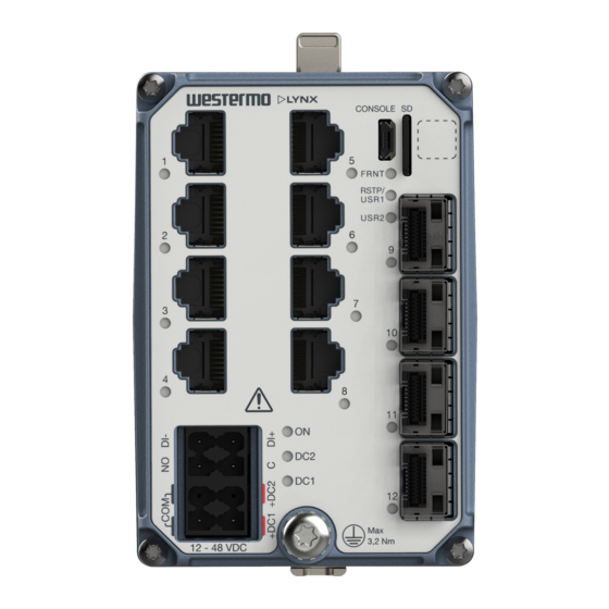
Page 12: Hardware Overview
Warning symbol, see warning in Power Input and I/O Connection [13] LED indicators The base MAC address and production date of the product is included in the front label QR code Figure 3. Location of interface ports and LED indicators Lynx 5500 Series... -
Page 13: Connector Information
USB cable that connects to a FTDI FT232R USB to serial converter internally. For drivers, refer to www.ftdichip.com and download the appropriate VCP driver 3.4.3. Micro SD To insert the micro SD card correctly, turn the gold plated pins to the left side. Lynx 5500 Series... -
Page 14: Sfp Transceivers
Figure 4. Insertion of micro SD card 3.4.4. SFP Transceivers The product supports UL and IEC certified transceivers only. See Westermo's modular transceivers datasheets 100 Mbit and 1 Gbit for supported SFP transceivers, which can be downloaded from the product support pages at www.westermo.com/support/product-... -
Page 15: Led Indicators
USR2 Configurable, see WeOS user Guide TX/FX No link ports GREEN Link established GREEN Data traffic indication FLASH YELLOW Port alarm and no link. Or if FRNT or RSTP mode, port is blocked. Table 8. LED indicators Lynx 5500 Series... -
Page 16: Dimensions
3.6. Dimensions Dimensions are stated in mm and are regardless model. 92 (DIN surface to front) 2 to 8 2 to 8 Figure 5. Dimensional drawing Lynx 5500 Series... -
Page 17: Installation
Snap on the product to the DIN-rail according to the figure. Figure 6. Mounting of product 4.2. Removal of Product To remove the product either push the support pin down, or press down the support at the back with a screwdriver. Figure 7. Removal of product Lynx 5500 Series... -
Page 18: Earth Connection
/ right the unit. Spacing is recommended for the use of unit in full operating temperature range and service life. 10mm 10mm CONSOLE SD FRNT RSTP/ USR1 USR2 3,2 Nm 12 - 48 VDC Figure 9. Miminum spacing of product Lynx 5500 Series... -
Page 19: Specifications
Conductor cross section 0.2 -2.5 mm² (AWG 24 - 12) Stripping length cable 10 mm Circuit type SELV ≤ 2.9 mA at 60 VDC Maximum voltage/current 60 VDC, I Voltage levels Logic one: >8 VDC Logic zero: <5 VDC Lynx 5500 Series... - Page 20 Data rate 100 Mbit/s, 1000 Mbit/s Duplex Full or half, manual or auto Transmission range Depending on transceiver Connector SFP slot holding fibre transceiver SFP ports are 9 to 12 100 Mbit/s or 1000 Mbit/s tranceiver supported Lynx 5500 Series...
- Page 21 Up to 480 Mbps (high-speed mode) Circuit type SELV Maximum supply current 100 mA Connector USB Micro B connector in device mode Micro SD Electrical specification Secure Digital 2.0 Circuit type SELV Maximum supply current 100 mA Connector Micro SD connector Lynx 5500 Series...
-
Page 22: Type Tests And Environmental Conditions
CM: ±2.5 kV 200 Ω, 1 MHz, Direct on shield Radiated RF EN 61000-4-3 Enclosure 20 V/m, 80% AM (1kHz) at 80 MHz to 2,7 immunity GHz, spot freq.: 80, 160, 380, 450, 900, 1600, 1850 MHz Lynx 5500 Series... - Page 23 I/O port to all other ports IEEE 802.3 Ethernet ports to all other ports Dielectric strength AREMA Power port (DC) 2121 VDC, 60 s to all other ports 1500 VAC rms, 60 s I/O port to all other ports Lynx 5500 Series...
- Page 24 1500 VAC rms, 60 s to all other ports I/O port to all other ports IEEE 802.3 Ethernet ports to all other ports Impulse withstand IEEE 802.3 Ethernet ports to 2.4 kV all other ports Table 9. EMC and electrical conditions Lynx 5500 Series...
- Page 25 , 11 ms, 3 x 6 shocks (saw tooth) Bump Operational Class 2, 20g/16 rms, 6 x 1000 bumps 60255-21-2 Enclosure EN 61010-1 Aluminum Fire enclosure Weight 690 gr Degree of protection EN 60529 Enclosure IP40 Cooling Convection Lynx 5500 Series...
- Page 26 Method 3, 21 days corresponds to Harsh Industrial Environment G3 which is defined in ANSI/ISA 17.04: 2015 The power and I/O cables need to be fastened 200 mm or closer to the unit. The same recommendation applies to the Ethernet cables. Table 10. Environmental and mechanical conditions Lynx 5500 Series...
-
Page 27: Revision Notes
6. Revision Notes Revision Date Change description Rev. A 2019-12 First revision Lynx 5500 Series... - Page 28 Westermo • SE-635 35 Stora Sundby, Sweden Tel +46 16 42 80 00 Fax +46 16 42 80 01 E-mail: info@westermo.com www.westermo.com 6643-25001 REV A 2019 12 Westermo Network Technologies AB, Sweden...
Need help?
Do you have a question about the Lynx 5500 Series and is the answer not in the manual?
Questions and answers