Table of Contents
Advertisement
Quick Links
Advertisement
Table of Contents

Subscribe to Our Youtube Channel
Related Manuals for Westermo MDI-110 Series


Summary of Contents for Westermo MDI-110 Series
-
Page 1: Ethernet Switch
MDI-110 Series User’s Manual Industrial Managed Ethernet Switch... - Page 2 Copyright Notice Copyright © 2010 Westermo Technology Co., Ltd. All rights reserved. Reproduction in any form or by any means without permission is prohibited. ...
- Page 3 Federal Communications Commission (FCC) Statement This equipment has been tested and found to comply with the limits for a Class A digital device, pursuant to Part 15 of the FCC Rules. These limits are designed to provide reasonable protection against harmful interference when the equipment is operated in a commercial environment. This equipment generates, uses, and can radiate radio frequency energy and, if not installed and used in accordance with the ...
-
Page 4: Table Of Contents
Index 1 Introduction ......................6 1.1 Overview ....................6 1.2 Major Features ................... 7 1.3 Package List ....................7 2 Hardware Installation .....................8 2.1 Hardware Introduction ................8 2.2 Wiring Power Inputs .................. 9 2.3 Wiring Digital Input .................. 10 2.4 Wiring Digital Output ................11 2.5 Wiring Earth Ground ................11 2.6 Wiring Fast Ethernet Ports ............... - Page 5 5 Appendix ......................125 5.1 Pin Assignment of the RS‐232 Console Cable ........125 5.2 Private MIB ..................... 126 5.3 Revision History..................127 ...
-
Page 6: Introduction
RS232 console cable to manage the switch by Command Line Interface (CLI). CLI commands are Cisco‐Like commands, your engineers who are familiar with Cisco products don’t need to learn new rules for CLI commands. Security is enhanced with advanced features such as 802.1Q VLAN and Port/IP security. Performance is optimized by QoS and IGMP Snooping/Query. Westermo ring technology, Multiple Super Ring, enables superb self‐healing capability for network failure. The fastest failover time is enhanced from 300ms to 5ms for 10/100TX RJ‐45 ports, and 30ms for 100FX and Gigabit Fiber. This is Westermo patented ring technology, which is registered in most countries. For interoperability with your existed network, MDI‐110 series also come with an advanced redundant network solution, Ring Coupling and Rapid Dual Homing ... -
Page 7: Major Features
transmission for industrial applications. MDI‐110 Series will be your best option for highly‐managed industrial network. Major Features The products have the following features: MDI‐110‐F3G: 7 10/100 Base TX and 3 Gigabit RJ‐45/SFP combo (10/100/1000 Base‐TX, 100 FX, Gigabit SX/LX) MDI‐110‐F3: 7 10/100 Base TX and 3 100Mbps RJ‐45/SFP combo (10/100 Base‐TX, 100 FX SX/LX) 32G switch Fabric, 8K MAC address Patented Multiple Super Ring (MSR), minimum Recovery time <5ms Rapid Daul Homing, which allows switch connect to third party network with maximum 7 multiple redundant paths. ... -
Page 8: Hardware Installation
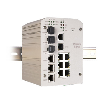
2 Hardware Installation This chapter includes hardware introduction, installation and configuration information. Following topics are covered in this chapter: 2.1 Hardware Introduction Dimension Panel Layout Bottom View 2.2 Wiring Power Inputs 2.3 Wiring Digital Input 2.4 Wiring Relay Output 2.5 Wiring Ethernet Ports 2.6 Wiring Combo Ports 2.7 Wiring RS‐232 console cable 2.8 DIN‐Rail Mounting Installation 2.9 Wall‐Mounting Installation Hardware Introduction Dimension The switch dimension (W x H x D) is 96mm x 137mm x 119mm ... -
Page 9: Wiring Power Inputs
Panel Layout MDI‐110‐F3G MDI‐110‐F3 Bottom View The bottom view of the switch consists of three terminal block connectors with two DC power inputs, two Digital Inputs, 2 Relay Outputs and 1 Earth Ground. Wiring Power Inputs Follow below steps to wire the redundant DC power inputs. ... -
Page 10: Wiring Digital Input
Insert positive and negative wires into V+ and V‐ contacts respectively of the terminal block connector Tighten the wire‐clamp screws to prevent DC wires from being loosened. Power 1 and Power 2 support power redundancy and polarity reverse protection functions. Positive and negative power system inputs are both accepted, but Power 1 and Power 2 must apply the same mode. Note 1: It is a good practice to turn off input and load power, and to unplug power ... -
Page 11: Wiring Digital Output
actively drive these pins high or low. The embedded software UI allows you to read and set the value to the connected device. The power input voltage of logic low is DC 0~10V. Logic high is DC 11~30V. Wire the digital input just like wiring the power input introduced in chapter 2.2. Wiring Digital Output The switch provides 2 digital outputs, also known as Relay Output. The relay contacts are energized (open) for normal operation and will close for fault conditions. The fault conditions include power failure, Ethernet port link break or other pre‐defined events which can be configured in the switch UI. ... -
Page 12: Wiring Fast Ethernet Ports
DC1 DC2 Wiring Fast Ethernet Ports The switch includes 7 RJ‐45 Fast Ethernet ports. The fast Ethernet ports support 10Base‐T and 100Base‐TX, full or half duplex modes. All the fast Ethernet ports will auto‐detect the signal from connected devices to negotiate the link speed and duplex mode. Auto MDI/MDIX allows users to connect another switch, hub or workstation without changing straight through or crossover cables. Note that crossover cables simply cross‐connect the transmit lines at each end to the received lines at the opposite end. Straight‐through Cabling Schematic Cross‐over Cabling Schematic Note that Ethernet cables use pins 1, 2, 3, and 6 of an 8‐pin RJ‐45 connector. The signals of these pins are converted by the automatic MDI‐X function, as shown in the table below: Pin MDI‐X Signals MDI Signals 1 RD+ TD+ 2 RD‐ TD‐ 3 TD+ RD+ ... -
Page 13: Wiring Combo Ports
Wiring Combo Ports The switch includes 3 RJ‐45/SFP combo ports. The SFP ports accept standard MINI GBIC SFP transceiver. To ensure system reliability, it is recommended to use the Westermo i‐line certificated SFP Transceiver. The certificated SFP transceiver includes 100Base‐FX single/multi mode, 1000Base‐SX/LX single/multi mode ranger from 550m to 80KM. ... - Page 14 1. Use the screws to attach DIN‐Rail clip to the rear panel. 2. To remove DIN‐Rail clip, reverse step 1. Follow the steps below to mount to the DIN‐Rail track: First, insert the upper end of DIN‐Rail clip into the back of DIN‐Rail track from its upper side. Lightly push the bottom of DIN‐Rail clip into the track. ...
-
Page 15: Wall-Mounting Installation
Check if DIN‐Rail clip is tightly attached on the track. To remove the switch from the track, reverse the steps above. Notes: The DIN Rail should compliance with DIN EN50022 standard. Using wrong DIN rail may cause system install unsafe. 2.10 Wall‐Mounting Installation Follow the steps below to install the switch with the wall mounting plate. 1. To remove DIN‐Rail clip from the switch, loosen the screws from DIN‐Rail clip. 2. Place the wall mounting plate on the rear panel of the switch. 3. Use the screws to tighten the wall mounting plate onto the switch. ... -
Page 16: Safety Warming
4. Use the hook holes at the corners of the wall mounting plate to hang the switch onto the wall. 5. To remove the wall mounting plate, reverse the steps above. Note: To avoid damage the internal circuit, be sure use the screw included in the package to screw and tight the wall‐mount kit onto the rear side of the switch. The specification of screw is M3 in 6 mm length. 2.11 Safety Warming The Equipment intended for installation in a Restricted Access Location. The warning test is provided in user manual. Below is the information: ”For tilslutning af de ovrige ledere, se medfolgende installationsvejledning”. -
Page 17: Preparation For Management
Following topics are covered in this chapter: 3.1 Preparation for Serial Console 3.2 Preparation for Web Interface 3.3 Preparation for Telnet console Preparation for Serial Console In the package, Westermo attached one RS‐232 DB‐9 to RJ‐45 console cable. Please attach RS‐232 DB‐9 connector to your PC COM port, connect RJ‐45 to the Console port of the switch. If you lose the cable, please follow the console cable PIN assignment to find one. (Refer to the appendix). 1. Go to Start ‐> Program ‐> Accessories ‐> Communication ‐> Hyper Terminal 2. Give a name to the new console connection. ... -
Page 18: Preparation For Web Interface
1. Verify that your network interface card (NIC) is operational, and that your operating system supports TCP/IP protocol. 2. Wire DC power to the switch and connect your switch to your computer. 3. Make sure that the switch default IP address is 192.168.2.200. 4. Change your computer IP address to 192.168.2.2 or other IP address which is located in the 192.168.2.x (Network Mask: 255.255.255.0) subnet. 5. Switch to DOS command mode and ping 192.168.2.200 to verify a normal response time. Launch the web browser and Login. 6. Launch the web browser (Internet Explorer or Mozilla Firefox) on the PC. 7. Type http://192.168.2.200 (or the IP address of the switch). And then press Enter. 8. The login screen will appear next. 9. Key in user name and the password. Default user name is admin and password westermo. ... - Page 19 Once you enter the web‐based management interface, you can freely change the IP address to fit your network environment. Note 1: IE 5.0 or later versions do not allow Java applets to open sockets by default. Users have to directly modify the browser settings to selectively enable Java applets to use network ports. Note 2: The Web UI connection session will be logged out automatically if you don’t give any input after 30 seconds. After logged out, you should re‐login and key in correct user name and password again. 3.2.2 Secured Web Interface Westermo web management page also provides secured management HTTPS ...
-
Page 20: Preparation For Telnet Console
Launch the web browser (Internet Explorer or Mozila Firefox) on the PC. Type https://192.168.2.200 (or the IP address of the switch). And then press Enter. The popup screen will appear and request you to trust the secured HTTPS connection. Press Yes to trust it. The login screen will appear next. Key in the user name and the password. The default user name is admin and password is westermo. Click on Enter or OK. Welcome page of the web‐based management interface will then appear. Once you enter the web‐based management interface, all the commands you see are the same as what you see by HTTP login. Preparation for Telnet Console 3.3.1 Telnet The switch supports Telnet console. You can connect to the switch by Telnet ... - Page 21 by command line interface. The SSH connection can secure all the configuration commands you sent to the switch. SSH is a client/server architecture while the switch is the SSH server. When you want to make SSH connection with the switch, you should download the SSH client tool first. SSH Client There are many free, sharewares, trials or charged SSH clients you can find on the internet. Fox example, PuTTY is a free and popular Telnet/SSH client. We’ll use this tool to demonstrate how to login by SSH. Note: PuTTY is copyright 1997‐2006 Simon Tatham. 1. Open SSH Client/PuTTY In the Session configuration, enter the Host Name (IP Address of your switch) and Port number (default = 22). Choose the “SSH” protocol. Then click on “Open” to start the SSH session console. 2. After click on Open, then you can see the cipher information in the popup screen. Press Yes to accept the Security Alert. ...
- Page 22 3. After few seconds, the SSH connection to the switch is opened. 4. Type the Login Name and its Password. The default Login Name and Password are admin/westermo. 5. All the commands you see in SSH are the same as the CLI commands you see via RS232 console. The next chapter will introduce in detail how to use command line to configure the switch. ...
-
Page 23: Feature Configuration
4 Feature Configuration This chapter explains how to configure software features. There are four ways to access the switch: Serial console, Telnet, Web browser and SNMP. Following topics are covered in this chapter: Command Line Interface (CLI) Introduction Basic Setting Port Configuration Network Redundancy VLAN Traffic Prioritization Multicast Filtering SNMP Security 4.10 Warning 4.11 Monitor and Diag 4.12 Device Front Panel 4.13 Save 4.14 Logout ... -
Page 24: Command Line Interface Introduction
Command Line Interface Introduction The Command Line Interface (CLI) is the user interface to the switch’s embedded software system. You can view the system information, show the status, configure the switch and receive a response back from the system by keying in a command. There are some different command modes. Each command mode has its own access ability, available command lines and uses different command lines to enter and exit. These modes are User EXEC, Privileged EXEC, Global Configuration, (Port/VLAN) Interface Configuration modes. User EXEC mode: As long as you login the switch by CLI. You are in the User EXEC mode. You can ping, telnet remote device, and show some basic information. Type enable to enter next mode, exit to logout. ? to see the command list Switch> enable Turn on privileged mode command exit Exit current mode and down to previous mode list... - Page 25 Global Configuration Mode: Press configure terminal in privileged EXEC mode. You can then enter global configuration mode. In global configuration mode, you can configure all the features that the system provides you. Type interface IFNAME/VLAN to enter interface configuration mode, exit to leave. ? to see the command list. Available command lists of global configuration mode. Switch# configure terminal Switch(config)# access-list Add an access list entry administrator Administrator account setting ...
- Page 26 Available command lists of the global configuration mode. Switch(config)# interface fa1 Switch(config-if)# acceptable Configure 802.1Q acceptable frame types of a port. auto-negotiation Enable auto-negotiation state of a given port description Interface specific description duplex Specify duplex mode of operation for a port End current mode and change to enable mode ...
- Page 27 Summary of the 5 command modes. Command Main Function Enter and Exit Method Prompt Mode User EXEC This is the first level of access. Enter: Login successfully Switch> User can ping, telnet remote Exit: exit to logout. device, and show some basic Next mode: Type enable to information enter privileged EXEC mode. Privileged In this mode, the system allows Enter: Type enable in User Switch# EXEC you to view current EXEC mode. configuration, reset default, Exec: Type disable to exit to reload switch, show system user EXEC mode. information, save Type exit to logout configuration…and enter global Next Mode: Type configure configuration mode. terminal to enter global configuration command. Global In global configuration mode, Enter: Type configure Switch(config)# ...
- Page 28 Here are some useful commands for you to see these available commands. Save your time in typing and avoid typing error. ? To see all the available commands in this mode. It helps you to see the next command you can/should type as well. Switch(config)# interface (?) IFNAME Interface's name vlan Select a vlan to configure (Character)? To see all the available commands starts from this character. Switch(config)# a? access-list Add an access list entry administrator Administrator account setting Set a static ARP entry ...
-
Page 29: Basic Setting
Basic Setting The Basic Setting group provides you to configure switch information, IP address, User name/Password of the system. It also allows you to do firmware upgrade, backup and restore configuration, reload factory default, and reboot the system. Following commands are included in this group: 4.2.1 Switch Setting 4.2.2 Admin Password 4.2.3 IP Configuration 4.2.4 Time Setting 4.2.5 DHCP Server 4.2.6 Backup and Restore 4.2.7 Firmware Upgrade 4.2.8 Factory Default ... - Page 30 Note: Always remember to select Save to save your settings. Otherwise, the settings you made will be lost when the switch is powered off. 4.2.2 Admin Password You can change the user name and the password here to enhance security Figure 4.2.2.1 Web UI of the Admin Password User name: You can key in new user name here. The default setting is admin. Password: You can key in new password here. The default setting is westermo. Confirm Password: You need to type the new password again to confirm it. Once you finish configuring the settings, click on Apply to apply your configuration. Figure 4.2.2.2 Popup alert window for Incorrect Username. ...
- Page 31 4.2.3 IP Configuration This function allows users to configure the switch’s IP address settings. DHCP Client: You can select to Enable or Disable DHCP Client function. When DHCP Client function is enabled, an IP address will be assigned to the switch from the network’s DHCP server. In this mode, the default IP address will therefore be replaced by the one assigned by DHCP server. If DHCP Client is disabled, then the IP address that you specified will be used instead. IP Address: You can assign the IP address reserved by your network for your switch. If DHCP Client function is enabled, you don’t need to assign an IP address to the switch, as it will be overwritten by DHCP server and shown here. The default IP is 192.168.2.200. ...
- Page 32 It also provides Daylight Saving function. Manual Setting: User can select Manual setting to change time as user wants. User also can click the button “Get Time from PC” to get PC’s time setting for switch. NTP client: Select the Time Setting Source to NTP client can let device enable the NTP client service. NTP client will be automatically enabled if you change Time source to NTP Client. The system will send request packet to acquire current time ...
- Page 33 13 (GMT‐05:00) Eastern Time (US & Canada) 14 (GMT‐05:00) Indiana (East) 15 (GMT‐04:00) Atlantic Time (Canada) 16 (GMT‐04:00) Caracas, La Paz 17 (GMT‐04:00) Santiago 18 (GMT‐03:00) NewFoundland 19 (GMT‐03:00) Brasilia 20 (GMT‐03:00) Buenos Aires, Georgetown ...
- Page 34 51 (GMT+06:00) Astana, Dhaka 52 (GMT+06:00) Sri Jayawardenepura 53 (GMT+06:30) Rangoon 54 (GMT+07:00) Bangkok, Hanoi, Jakarta 55 (GMT+07:00) Krasnoyarsk 56 (GMT+08:00) Beijing, Chongqing, Hong Kong, Urumqi 57 (GMT+08:00) Irkutsk, Ulaan Bataar 58 (GMT+08:00) Kuala Lumpur, Singapore ...
- Page 35 After selecting to enable DHCP Server function, type in the Network IP address for the DHCP server IP pool, Subnet Mask, Default Gateway address and Lease Time for client. Once you have finished the configuration, click Apply to apply your configuration Excluded Address: You can type a specific address into the IP Address field for the DHCP server reserved IP address. The IP address that is listed in the Excluded Address List Table will not be assigned to the network device. Add or remove an IP address from the Excluded Address List by clicking Add or Remove. ...
- Page 36 the Reload button to refresh the listing. DHCP Relay Agent You can select to Enable or Disable DHCP relay agent function, and then select the modification type of option 82 field. Relay policy drop: Drops the option 82 field and do not add any option 82 field. Relay policy keep: Keeps the original option 82 field and forwards to server. Relay policy replace: Replaces the existing option 82 field and adds new option 82 field. (This is the default setting) ...
- Page 37 can also browse the target folder and select existed configuration file to restore the configuration back to the switch. This mode is only provided by Web UI while CLI is not supported. TFTP Server mode: In this mode, the switch acts as TFTP client. Before you do so, make sure that your TFTP server is ready. Then please type the IP address of TFTP Server and Backup configuration file name. This mode can be used in both CLI and Web UI. TFTP Server IP Address: You need to key in the IP address of your TFTP Server here. Backup/Restore File Name: Please type the correct file name of the configuration file. ...
- Page 38 Note: point to the wrong file will cause the entire configuration missed. 4.2.7 Firmware Upgrade In this section, you can update the latest firmware for your switch. Westermo provides the latest firmware in the web site. The new firmware may include new features, bug fixes or other software changes. We’ll also provide the release notes for the update as well. For technical viewpoint, we suggest you use the ...
- Page 39 There are 2 modes for users to backup/restore the configuration file, Local File mode and TFTP Server mode. Local File mode: In this mode, the switch acts as the file server. Users can browse the target folder and then type the file name to backup the configuration. Users also can browse the target folder and select the existed configuration file to restore the configuration back to the switch. This mode is only provided by Web UI while CLI is not supported. TFTP Server mode: In this mode, the switch acts as the TFTP client. Before you do so, make sure that your TFTP server is ready. And then please type the IP address of TFTP Server IP address. This mode can be used in both CLI and Web UI. TFTP Server IP Address: You need to key in the IP address of your TFTP Server here. ...
- Page 40 Popup message screen to show you that have done the command. Click on OK to close the screen. Then please go to Reboot page to reboot the switch. Click on OK. The system will then auto reboot the device. Note: If you already configured the IP of your device to other IP address, when you use this command by CLI and Web UI, our software will not reset the IP address to default IP. The system will remain the IP address so that you can still ...
- Page 41 Switch(config)# hostname WORD Network name of this system Switch(config)# hostname SWITCH SWITCH(config)# System Location SWITCH(config)# snmp-server location Sweden System Contact SWITCH(config)# snmp-server contact support@westermo.se Display SWITCH# show snmp-server name SWITCH SWITCH# show snmp-server location Sweden SWITCH# show snmp-server contact support@westermo.se SWITCH>...
- Page 42 orwell success. Display SWITCH# show administrator Administrator account information name: orwell password: orwell IP Configuration IP Address/Mask SWITCH(config)# int vlan 1 (192.168.2.8, SWITCH(config-if)# ip 255.255.255.0 address dhcp SWITCH(config-if)# ip address 192.168.2.8/24 SWITCH(config-if)# ip dhcp client SWITCH(config-if)# ip dhcp client renew Gateway SWITCH(config)# ip route 0.0.0.0/0 192.168.2.254/24 Remove Gateway...
- Page 43 Note: By typing clock timezone ?, you can see the timezone list. Then choose the number of the timezone you want to select. Display SWITCH# sh ntp associations Network time protocol Status : Disabled Primary peer : N/A Secondary peer : N/A SWITCH# show clock Sun Jan 1 04:14:19 2006 (GMT) Greenwich Mean Time: Dublin, Edinburgh, Lisbon, London...
- Page 44 Switch(config-dhcp)# ip dhcp relay information policy replace drop Relay Policy keep Drop/Keep/Replace option82 field replace Show DHCP server Switch# show ip dhcp server statistics information Switch# show ip dhcp server statistics DHCP Server ON Address Pool 1 network:192.168.17.0/24 default-router:192.168.17.254 lease time:300 Excluded Address List IP Address ---------------...
- Page 45 IP or file name in this command. Restore Switch# copy tftp: 192.168.2.33/default.conf Configuration startup-config Show Startup Switch# show startup-config Configuration Show Running Switch# show running-config Configuration Firmware Upgrade Firmware Upgrade Switch# archive download-sw /overwrite tftp 192.168.2.33 mdi-110.bin Firmware upgrading, don't turn off the switch! Tftping file mdi-110.bin Firmware upgrading ..........
-
Page 46: Port Configuration
Port Configuration Port Configuration group enables you to enable/disable port state, or configure port auto‐negotiation, speed, and duplex, flow control, rate limit control and port aggregation settings. It also allows you to view port status and aggregation information. Following commands are included in this group: 4.3.1 Port Control 4.3.2 Port Status 4.3.3 Rate Control 4.3.4 Port Trunking 4.3.5 ... - Page 47 Duplex(10 Half), 100M Full Duplex(100 Full), 100M Half Duplex(100 Half), 1000M Full Duplex(1000 Full), 1000M Half Duplex(1000 Half). The default mode is Auto Negotiation mode. In Flow Control column, “Symmetric” means that you need to activate the flow control function of the remote network device in order to let the flow control of that corresponding port on the switch to work. “Disable” means that you don’t need to activate the flow control function of the remote network device, as the flow control of that corresponding port on the switch will work anyway. Once you finish configuring the settings, click on Apply to save the configuration. Technical Tips: If both ends are not at the same speed, they can’t link with each other. If both ends are not in the same duplex mode, they will be connected by half mode. 4.3.2 Port Status Port Status shows you current port status. The switch supports SFP fiber transceiver with Digital Diagnostic Monitoring (DDM) function that provides real time information of SFP transceiver and allows user to diagnostic the optical fiber signal received and launched. The information of SFP DDM will listing on another table. The description of the columns is as below: ...
- Page 48 Note: 1. Most of the SFP transceivers provide vendor information which allows your switch to read it. The UI can display vendor name, wave length and distance of all Westermo i‐line SFP transceiver family. If you see Unknown info, it may mean that the vendor doesn’t provide their information or that the information of their transceiver can’t be read. ...
- Page 49 Rate limiting is a form of flow control used to enforce a strict bandwidth limit at a port. You can program separate transmit (Egress Rule) and receive (Ingress Rule) rate limits at each port, and even apply the limit to certain packet types as described below. Packet type: You can select the packet type that you want to filter. The packet types of the Ingress Rule listed here include Broadcast Only / Broadcast and multicast / Broadcast, Multicast and Unknown Unicast or All. The packet types of the Egress Rule (outgoing) only support all packet types. Rate: This column allows you to manually assign the limit rate of the port. Valid values are from 1Mbps‐100Mbps for fast Ethernet ports and gigabit Ethernet ports. The step of the rate is 1 Mbps. Default value of Ingress Rule is “8” Mbps; ...
- Page 50 Link Aggregation Group (LAG), Link Aggregation Control Protocol, Ethernet Trunk, Ether Channel…etc. Most of the implementations now conform to IEEE standard, 802.3ad. The aggregated ports can interconnect to the other switch which also supports Port Trunking. Westermo Supports 2 types of port trunking. One is Static Trunk, the other is 802.3ad. When the other end uses 802.3ad LACP, you should assign 802.3ad LACP to the trunk. When the other end uses non‐802.3ad, you can then use Static Trunk. There are 2 configuration pages, Aggregation Setting and Aggregation Status. Aggregation Setting ...
- Page 51 Group ID: Display Trunk 1 to Trunk 5 set up in Aggregation Setting. Type: Static or LACP set up in Aggregation Setting. Aggregated: When LACP links well, you can see the member ports in Aggregated column. Individual: When LACP is enabled, member ports of LACP group which are not connected to correct LACP member ports will be displayed in the Individual column. Link Down: When LACP is enabled, member ports of LACP group which are not linked up will be displayed in the Link Down column. 4.3.5 Command Lines for Port Configuration Feature Command Line Port Control Port Control –...
- Page 52 Switch(config)# sfp ddm eject eject SFP DDM transceiver All DDM interface Example: Switch(config)# sfp ddm eject all DDM SFP on Port 9 normally ejected. DDM SFP on Port 9 normally ejected. All DDM SFP normally ejected. Switch(config)# interface gigabitethernet10 eject port 10 SFP DDM transceiver.
- Page 53 Ingress Filtering : Disabled Acceptable Frame Type : All Port Security : Disabled Auto Negotiation : Disable Loopback Mode : None STP Status: forwarding Default CoS Value for untagged packets is 0. Mdix mode is Disable. Medium mode is Copper. Switch# show sfp ddm show SFP DDM information Port 8...
- Page 54 Type broadcast Limit Broadcast frames flooded-unicast Limit Broadcast, Multicast and flooded unicast frames multicast Limit Broadcast and Multicast frames Switch(config-if)# rate-limit ingress mode broadcast Set the ingress limit mode broadcast ok. Rate Control - Switch(config-if)# rate-limit ingress bandwidth Bandwidth <0-100> Limit in magabits per second (0 is no limit) Switch(config-if)# rate-limit ingress bandwidth 8 Set the ingress rate limit 8Mbps for Port 1.
- Page 55 FLAGS: I -> Individual P -> In channel D -> Port Down Trunk Group GroupID Protocol Ports --------+---------+------------------------------------ Static 6(D) 7(P) Switch# ...
-
Page 56: Network Redundancy
Network Redundancy It is critical for industrial applications that network remains non‐stop. The switch firmware supports standard RSTP, Multiple Super Ring, Rapid Dual Homing. Multiple Super Ring (MSR) technology ranks the fastest restore and failover time in the world, 0 ms for restore and about 5 milliseconds for failover for copper. Advanced Rapid Dual Homing (RDH) technology also facilitates the switch to connect with a core managed switch easily and conveniently. With RDH technology, you can also couple several Rapid Super Rings or RSTP cloud together, which is also known as Auto Ring Coupling. Besides ring technology, the switch also supports 802.1D‐2004 version Rapid Spanning ... - Page 57 RSTP Mode: You must first enable STP/RSTP mode, before configuring any related parameters. Parameter settings required for both STP and RSTP are the same. Note that 802.1d refers to STP mode, while 802.1w refers to faster RSTP mode. Bridge Configuration Priority (0‐61440): RSTP uses bridge ID to determine the root bridge, the bridge with the highest bridge ID becomes the root bridge. The bridge ID is composed of bridge priority and bridge MAC address. So that the bridge with the highest priority becomes the highest bridge ID. If all the bridge ID has the same priority, the bridge with the lowest MAC address will then become the root bridge. Note: The bridge priority value must be in multiples of 4096. A device with a lower number has a higher bridge priority. Ex: 4096 is higher than 32768. ...
- Page 58 If the switch is not the root bridge, and if it has not received a hello message from the root bridge in an amount of time equal to Max Age, then the switch will reconfigure itself as a root bridge. Once two or more devices on the network are recognized as a root bridge, the devices will renegotiate to set up a new spanning tree topology. Hello Time (1‐10): Enter a value from 1 to 10 seconds here. This is a periodic timer that drives the switch to send out BPDU (Bridge Protocol Data Unit) packet to check current STP status. The ...
- Page 59 means to auto select P2P or Share mode. “P2P” means P2P is enabled, while “Share” means P2P is disabled. Admin Edge: A port directly connected to the end stations cannot create a bridging loop in the network. To configure this port as an edge port, set the port to the Enable state. When the non‐bridge device connects an admin edge port, this port will be in blocking state and turn to forwarding state in 4 seconds. Once you finish your configuration, click on Apply to save your settings. 4.4.2 RSTP Info This page allows you to see the information of the root switch and port status. Root Information: You can see root Bridge ID, Root Priority, Root Port, Root Path ...
- Page 60 Typically, the managed switches are connected in series and the last switch is connected back to the first one. The Multiple Super Ring has enhanced Ring Master selection and faster recovery time. It is also enhanced for more complex ring application. This page allows you to enable the settings for Multiple Super Ring and Rapid Dual Homing. New Ring: To create a Rapid Super Ring, just fill in the Ring ID which has range from 0 to 31. If the name field is left blank, the name of this ring will automatically naming with Ring ID. ...
- Page 61 a Ring, then it determines the blocking port. The Port with higher Path Cost in the two ring Port will become the blocking port, If the Path Cost is the same, the port with larger port number will become the blocking port. Ring Port2: Assign another port for ring connection Path Cost: Change the Path Cost of Ring Port2 Rapid Dual Homing: Rapid Dual Homing is an important feature of MSR. When you want to connect multiple RSR or form a redundant topology with other vendors, RDH could allow you to have maximum 7 multiple links for redundancy without any problem. In Rapid Dual Homing, you don’t need to configure specific port to connect to other ...
- Page 62 Blocking Port: This field shows which is blocked port of RM. Role Transition Count: This means how many times this switch has changed its Role from nonRM to RM or from RM to nonRM. Role state Transition Count: This number means how many times the Ring status has been transformed between Normal and Abnormal state. 4.4.5 Command Lines: Feature Command Line RSTP Enable Switch(config)# spanning-tree enable Disable Switch (config)# spanning-tree disable RSTP mode Switch(config)# spanning-tree mode rapid-stp SpanningTree Mode change to be RSTP(802.1w) .
- Page 63 Link Type - P2P Switch(config-if)# spanning-tree link-type point-to-point Link Type – Share Switch(config-if)# spanning-tree link-type shared Edge Port Switch(config-if)# spanning-tree edge-port enable Switch(config-if)# spanning-tree edge-port disable RSTP Info Active status Switch# show spanning-tree active Rapid Spanning-Tree feature Enabled Spanning-Tree BPDU transmission-limit Root Address 0007.7c01.0386 Priority 4096...
- Page 64 Port Info Switch# show spanning-tree port detail fa7 (Interface_ID) Rapid Spanning-Tree feature Enabled Port 128.6 as Disabled Role is in Disabled State Port Path Cost 200000, Port Identifier 128.6 RSTP Port Admin Link-Type is Auto, Oper Link-Type is Point-to-Point RSTP Port Admin Edge-Port is Enabled, Oper Edge-Port is Edge Designated root has priority 32768, address 0007.7c00.0112...
- Page 65 <0-255> valid range is 0 to 255 default set default Switch(config)# super-ring priority 100 Ring Port Switch(config-multiple-super-ring)# port IFLIST Interface list, ex: fa1,fa3-5,gi8-10 cost path cost Switch(config-multiple-super-ring)# port fa1,fa2 Ring Port Cost Switch(config-multiple-super-ring)# port cost <0-255> valid range is 0 or 255 default set default (128)valid range is 0 or 255 Switch(config-multiple-super-ring)# port cost 100 <0-255>...
- Page 66 Giga Copper : N/A Configuration : Version : Rapid Super Ring Priority : 128 Ring Port : fa1, fa2 Path Cost : 100, 200 Dual-Homing II : Disabled Statistics : Watchdog sent 0, received 0, missed Link Up sent 0, received Link Down sent 0, received Role Transition count 0...
-
Page 67: Vlan
VLAN A Virtual LAN (VLAN) is a “logical” grouping of nodes for the purpose of limiting a broadcast domain to specific members of a group without physically grouping the members together. That means, VLAN allows you to isolate network traffic so that only members of VLAN could receive traffic from the same VLAN members. Basically, creating a VLAN from a switch is the logical equivalent of physically reconnecting a group of network devices to another Layer 2 switch, without actually disconnecting these devices from their original switches. ... - Page 68 PVID: The abbreviation of the Port VLAN ID. Enter port VLAN ID here. PVID allows the switches to identify which port belongs to which VLAN. To keep things simple, it is recommended that PVID is equivalent to VLAN IDs. The values of PVIDs are from 0 to 4095. But, 0 and 4095 are reserved. You can’t input these 2 PVIDs. 1 is the default value. 2 to 4094 are valid and available in this column. Type the PVID you’d like to configure here. Accept Frame Type: This column defines the accepted frame type of the port. There are 2 modes you can select, Admit All and Tag Only. Admit All mode means that the port can accept both tagged and untagged packets. Tag Only mode means that the port can only accept tagged packets. Ingress Filtering: Ingress filtering helps VLAN engine to filter out undesired traffic on a port. When Ingress Filtering is enabled, the port checks whether the incoming ...
- Page 69 Figure 4.5.2.1 Web UI of the VLAN Configuration. Management VLAN ID: The switch supports management VLAN. The management VLAN ID is the VLAN ID of the CPU interface so that only member ports of the management VLAN can ping and access the switch. The default management VLAN ID is 1. Static VLAN: You can assign a VLAN ID and VLAN Name for new VLAN here. VLAN ID is used by the switch to identify different VLANs. Valid VLAN ID is between 1 and 4094. 1 is the default VLAN. ...
- Page 70 port of the management VLAN; otherwise the administrator can’t access the switch via the network. Note: Currently the switch only support max 64 group VLAN. Static VLAN Configuration You can see the created VLANs and specify the egress (outgoing) port rule to be Untagged or Tagged here. Figure 4.5.2.3 Static VLAN Configuration table. You can see that new VLAN 3 is created. VLAN name is test. Egress rules of the ports are not configured now. Figure 4.5.2.4 Configure Egress rule of the ports. ‐‐ : Not available U: Untag: Indicates that egress/outgoing frames are not VLAN tagged. T : Tag: Indicates that egress/outgoing frames are to be VLAN tagged. Steps to configure Egress rules: Select the VLAN ID. Entry of the selected VLAN turns to light blue. Assign Egress rule of the ports to U or T. Press Apply to apply ...
- Page 71 GVRP Protocol: Allow user to enable/disable GVRP globally. State: After enable GVRP globally, here still can enable/disable GVRP by port. Join Timer: Controls the interval of sending the GVRP Join BPDU. An instance of this timer is required on a per‐Port, per‐GARP Participant basis Leave Timer: Control the time to release the GVRP reservation after received the GVRP Leave BPDU. An instance of the timer is required for each state machine that is in the LV state Leave All Timer: Controls the period to initiate the garbage collection of registered VLAN. The timer is required on a per‐Port, per‐GARP Participant basis 4.5.4 VLAN Table This table shows you current settings of your VLAN table, including VLAN ID, Name, Status, and Egress rule of the ports. ...
- Page 72 VLAN ID: ID of the VLAN. Name: Name of the VLAN. Status: Static shows this is a manually configured static VLAN. Unused means this VLAN is created by UI/CLI and has no member ports. This VLAN is not workable yet. Dynamic means this VLAN is learnt by GVRP. After created the VLAN, the status of this VLAN will remain in Unused status until you add ports to the VLAN. 4.5.5 CLI Commands of the VLAN Command Lines of the VLAN port configuration, VLAN configuration and VLAN table display Feature Command Line VLAN Port Configuration VLAN Port PVID Switch(config-if)# switchport trunk native vlan 2 Set port default vlan id to 2 success Port Accept Frame Switch(config)# inter fa1 Type Switch(config-if)# acceptable frame type all...
- Page 73 (for fast Ethernet Switch(config-if)# ingress filtering enable port 1) ingress filtering enable Switch(config-if)# ingress filtering disable ingress filtering disable Egress rule – Switch(config-if)# switchport access vlan 2 Untagged (for VLAN 2) switchport access vlan - success Egress rule – Tagged Switch(config-if)# switchport trunk allowed vlan (for VLAN 2) add 2...
- Page 74 vlan 2 success Switch(config)# interface vlan 2 Switch(config-if)# Note: In CLI configuration, you should create a VLAN interface first. Then you can start to add/remove ports. Default status of the created VLAN is unused until you add member ports to it. Remove VLAN Switch(config)# no vlan 2 no vlan success...
- Page 75 Switch(config-if)# no shutdown ->Turn on the VLAN Display – VLAN table Switch# sh vlan VLAN Name Status Trunk Ports Access Ports ---- ------------ ------- -------------------------- VLAN1 Static fa1-7,gi8-10 VLAN2 Unused test Static fa4-7,gi8-10 fa1-3,fa7,gi8-10 Switch# show interface vlan1 Display – VLAN interface interface vlan1 is up, line protocol detection is information...
- Page 76 timer Management VLAN Management VLAN Switch(config)# int vlan 1 (Go to management VLAN) Switch(config-if)# no shutdown Display Switch# show running-config interface vlan1 ip address 192.168.2.200/24 ip igmp no shutdown ...
-
Page 77: Traffic Prioritization
Traffic Prioritization Quality of Service (QoS) provides traffic prioritization mechanism which allows users to deliver better service to certain flows. QoS can also help to alleviate congestion problems and ensure high‐priority traffic is delivered first. This section allows you to configure Traffic Prioritization settings for each port with regard to setting priorities. QOS supports 4 physical queues, weighted fair queuing (WRR) and Strict Priority scheme, which follows 802.1p COS tag and IPv4 TOS/DiffServ information to prioritize the traffic of your industrial network. ... - Page 78 You can freely assign the mapping table or follow the suggestion of the 802.1p standard. Westermo uses 802.p suggestion as default values. You can find CoS values 1 and 2 are mapped to physical Queue 0, the lowest queue. CoS values 0 and 3 are mapped to physical Queue 1, the low/normal physical queue. CoS ...
- Page 79 After configuration, press Apply to enable the settings. 4.6.3 DSCP‐Queue Mapping This page is to change DSCP values to Physical Queue mapping table. Since the switch fabric supports 4 physical queues, Lowest, Low, Middle and High. Users should therefore assign how to map DSCP value to the level of the physical queue. You can freely change the mapping table to follow the upper layer 3 switch or routers’ DSCP setting. ...
- Page 80 Command Lines of the Traffic Prioritization configuration Feature Command Line QoS Setting Queue Scheduling – Switch(config)# qos queue-sched Strict Priority Strict Priority wrr Weighted Round Robin (Use an 8,4,2,1 weight) Switch(config)# qos queue-sched sp <cr> Queue Scheduling - WRR Switch(config)# qos queue-sched wrr Port Setting – CoS Switch(config)# interface fa1 (Default Port Priority) Switch(config-if)# qos cos...
- Page 81 DSCP first COS only COS only COS only COS only COS only COS only COS only COS only COS only Display – Port Setting – Switch# show qos port-cos CoS (Port Default Port Default Cos : Priority) Port CoS -----+---- CoS-Queue Mapping Format Switch(config)# qos cos-map...
- Page 82 Map CoS 3 to Queue 1 Switch(config)# qos cos-map 3 1 The CoS to queue mapping is set ok. Map CoS 4 to Queue 2 Switch(config)# qos cos-map 4 2 The CoS to queue mapping is set ok. Map CoS 5 to Queue 2 Switch(config)# qos cos-map 5 2 The CoS to queue mapping is set ok.
- Page 83 1 | 0 0 0 0 0 0 0 0 0 0 2 | 0 0 0 0 1 1 1 1 1 1 3 | 1 1 2 2 2 2 2 2 2 2 4 | 2 2 2 2 2 2 2 2 3 3 5 | 3 3 3 3 3 3 3 3 3 3 6 | 3 3 3 3 ...
-
Page 84: Multicast Filtering
Multicast Filtering For multicast filtering, the switch uses IGMP Snooping technology. IGMP (Internet Group Management Protocol) is an Internet Protocol that provides a way for internet device to report its multicast group membership to adjacent routers. Multicasting allows one computer on the internet to send data to a multitude of other computers that have identified themselves as being interested ... - Page 85 4.7.1 IGMP Snooping This page is to enable IGMP Snooping feature, assign IGMP Snooping for specific VLAN, and view IGMP Snooping table from dynamic learnt or static manual key‐in. The switch supports IGMP snooping V1/V2/V3 automatically and IGMP query V1/V2. IGMP Snooping, you can select Enable or Disable here. After enabling IGMP Snooping, you can then enable IGMP Snooping for specific VLAN. You can enable IGMP Snooping for some VLANs so that some of the VLANs will support IGMP Snooping and others won’t. ...
- Page 86 4.7.2 IGMP Query This page allows users to configure IGMP Query feature. Since the switch can only be configured by member ports of the management VLAN, IGMP Query can only be enabled on the management VLAN. If you want to run IGMP Snooping feature in several VLANs, you should notice that whether each VLAN has its own IGMP Querier first. The IGMP querier periodically sends query packets to all end‐stations on the LANs or VLANs that are connected to it. For networks with more than one IGMP ...
- Page 87 4.7.3 Unknown Multicast After enabled IGMP Snooping, the known multicast can be filtered by IGMP Snooping mechanism and forwarded to the member ports of the known multicast groups. The other multicast streams which are not leant is so‐called unknown multicast, the switch decide how to forward them based on the setting of this page. ...
- Page 88 VLAN IGMP snooping is disabled on VLAN 3. Display – IGMP Snooping Switch# sh ip igmp Setting interface vlan1 enabled: Yes version: IGMPv1 query-interval; 125s query-max-response-time: 10s Switch# sh ip igmp snooping IGMP snooping is globally enabled Vlan1 is IGMP snooping enabled Vlan2 is IGMP snooping enabled Vlan3 is IGMP snooping disabled Display –...
- Page 89 …. interface vlan1 ip address 192.168.2.200/24 ip igmp no shutdown ……. Unknown Multicast Unknown Multicast - Switch(config)# mac-address-table multicast Enable Force filtering filtering (Send to All Ports) Filtering unknown multicast addresses ok! Switch(config)# no mac-address-table multicast Disable Force filtering filtering (Discard) Flooding unknown multicast addresses ok! Unknown Multicast –...
-
Page 90: Snmp
SNMP Simple Network Management Protocol (SNMP) is a protocol used for exchanging management information between network devices. SNMP is a member of the TCP/IP protocol suite. The switch series support SNMP v1 and v2c and V3. An SNMP managed network consists of two main components: agents and a manager. An agent is a management software module that resides in a managed switch. An agent translates the local management information from the managed device into a SNMP compatible format. The manager is the console through the network. Following commands are included in this group: 4.8.1 SNMP Configuration 4.8.2 SNMPv3 Profile 4.8.3 SNMP Traps ... - Page 91 4.8.2 SNMP V3 Profile SNMP v3 can provide more security functions when the user performs remote management through SNMP protocol. It delivers SNMP information to the administrator with user authentication; all of data between the switch and the administrator are encrypted to ensure secure communication. ...
- Page 92 SNMP Trap is the notification feature defined by SNMP protocol. All the SNMP management applications can understand such trap information. So you don’t need to install new application to read the notification information. This page allows users to Enable SNMP Trap, configure the SNMP Trap server IP, Community name, and trap Version V1 or V2. After configuration, you can see the change of the SNMP pre‐defined standard traps and Westermo pre‐defined traps. The pre‐defined traps can be found in Westermo private MIB. ...
- Page 93 4.8.4 CLI Commands of the SNMP Command Lines of the SNMP configuration Feature Command Line SNMP Community Read Only Community Switch(config)# snmp-server community public ro community string add ok Read Write Community Switch(config)# snmp-server community private community string add ok SNMP Trap Enable Trap Switch(config)# snmp-server enable trap Set SNMP trap enable ok. SNMP Trap Server IP Switch(config)# snmp-server host 192.168.2.33 without specific...
-
Page 94: Security
Security The switch provides several security features for you to secure your connection. The features include Port Security and IP Security. Following commands are included in this group: 4.9.1 Port Security 4.9.2 IP Security 4.9.3 IEEE 802.1x 4.9.4 CLI Commands of the Security 4.9.1 Port Security Port Security feature allows you to stop the MAC address learning for specific port. After stopping MAC learning, only the MAC address listed in Port Security ... - Page 95 Once you finish configuring the settings, click on Apply / Add to apply your configuration. 4.9.2 IP Security In IP Security section, you can set up specific IP addresses to grant authorization for management access to this switch via a web browser or Telnet. IP Security: Select Enable and Apply to enable IP security function. Add Security IP: You can assign specific IP addresses, and then press Add. Only these IP addresses can access and manage switch via a web browser or Telnet. Max security IP is 10. Security IP List: This table shows you added security IP addresses. You can press Remove to delete, Reload to reload the table. Once you finish configuring the settings, click on Apply to apply your configuration. ...
- Page 96 4.9.3 IEEE 802.1x 802.1X configuration IEEE 802.1X is the protocol that performing authentication to obtain access to IEEE 802 LANs. It is port‐base network access control. With the function, the switch could control which connection is available or not. System AuthControl: To enable or disable the 802.1x authentication. Authentication Method: Radius is a authentication server that provide key for authentication, with this method, user must connect switch to server. If user select ...
- Page 97 configure the authentication mode, authentication behavior, applied VLAN for each port and permitted communication. The following information will explain the port configuration. Port control: Force Authorized means this port is authorized; the data is free to in/out. Force unauthorized just opposite, the port is blocked. If users want to control this port with Radius Server, please select Auto for port control. Reauthentication: If enable this field, switch will ask client to re‐authenticate. The default time interval is 3600 seconds. ...
- Page 98 Sever Timeout: The timeout for server response for authenticating. Once you finish configuring the settings, click on Apply to apply your configuration. Click Initialize Selected to set the authorize state of selected port to initialize status. Click Reauthenticate Selected to send EAP Request to supplicant to request reauthentication. ...
- Page 99 Note: Rule: Add the static MAC, VLAN and Port binding first, then enable the port security to stop new MAC learning. Disable Port Security Switch(config-if)# no switchport port-security Enable new MAC addresses learning and aging activities! Display Switch# show mac-address-table static Destination Address Address Type Vlan Destination Port...
- Page 100 RADIUS Accounting Port number NOT given. (default=1813) Secondary RADIUS Server IP : 192.168.2.250 Secondary RADIUS Server Key : 5678 Secondary RADIUS Server Port : 1812 Secondary RADIUS Accounting Port : 1813 User name/password for Switch(config)# dot1x username Westermo passwd authentication Westermo vlan 1 ...
-
Page 101: Warning
4.10 Warning The switch provides several types of Warning features for you to remote monitor the status of end devices or the change of your network. The features include Fault Relay, System Log and SMTP E‐mail Alert. Following commands are included in this group: 4.10.1 Fault Relay 4.10.2 Event Selection 4.10.3 Syslog Configuration 4.10.4 SMTP Configuration 4.10.5 CLI Commands 4.10.1 Fault Relay The switch provides 2 digital outputs, also known as Relay Output. The relay contacts ... - Page 102 Event Type: DI State DI Number: Select DI 1 or DI 2. Select which DI you want to monitor. DI State: High or Low. Select the power voltage you want to monitor. How to configure: Select the DI Number you want to monitor and DI State, High or Low. For example: When DI 1 and High are selected, it means when DI 1 is pulled high, the system will short Relay Output and light DO LED. Event Type: Dry Output On Period (Sec): Type the period time to turn on Relay Output. Available range of a period is 0‐4294967295 seconds. Off Period (Sec): Type the period time to turn off Relay Output. Available range of a period is 0‐4294967295 seconds. How to configure: Type turn‐on period and turn‐off period when the time is reached, the system will turn on or off the Relay Output. If you connect DO to DI ...
- Page 103 Period” field and apply the setting, the relay will be trigger to form as a open circuit. This function is also available in CLI, SNMP management interface. See the following setting. Turn on the relay output Turn off the relay output ...
- Page 104 Event Type: Ping Failure IP Address: IP address of the target device you want to ping. Reset Time (Sec): Waiting time to short the relay output. Hold Time (Sec): Waiting time to ping the target device for the duration of remote device boot How to configure: After selecting Ping Failure event type, the system will turn Relay Output to short state and continuously ping the target device. When the ping ...
- Page 105 Once you finish configuring the settings, click on Apply to apply your configuration. 4.10.2 Event Selection Event Types can be divided into two basic groups: System Events and Port Events. System Events are related to the overall function of the switch, whereas Port Events related to the activity of the specific ports System Event Warning Event is sent when….. Device Cold Start Power is cut off and then reconnected. Device Warm Start Reboot the device by CLI or Web UI. Power 1 Failure Power 1 is failure. Power 2 Failure Power 2 is failure. Authentication failure An incorrect password, SNMP Community String is entered. Time Synchronize Failure Accessing to NTP Server is failure. Fault Relay The DO/Fault Relay is on. Super Ring Topology ...
- Page 106 Once you finish configuring the settings, click on Apply to apply your configuration. 4.10.3 SysLog Configuration System Log is useful to provide system administrator locally or remotely monitor switch events history. There are 2 System Log modes provided by the switch, local mode and remote mode. Local Mode: In this mode, the switch will print the occurred events selected in the Event Selection page to System Log table of the switch. You can monitor the ...
- Page 107 Once you finish configuring the settings, click on Apply to apply your configuration. Note: When enabling Local or Both mode, you can monitor the system logs in [Monitor and Diag] / [Event Log] page. 4.10.4 SMTP Configuration The switch supports E‐mail Warning feature. The switch will send the occurred events ...
- Page 108 Field Description SMTP Server IP Address Enter the IP address of the email Server Authentication Click on check box to enable password User Name Enter email Account name (Max.40 characters) Password Enter the password of the email account Confirm Password Re‐type the password of the email account You can set up to 4 email addresses to receive email alarm from the switch Rcpt E‐mail Address 1 The first email address to receive email alert from the switch (Max. 40 characters) Rcpt E‐mail Address 2 The second email address to receive email alert from the switch (Max. 40 characters) Rcpt E‐mail Address 3 The third email address to receive email alert from the switch (Max. 40 characters) Rcpt E‐mail Address 4 The fourth email address to receive email alert from the switch (Max. 40 characters) Once you finish configuring the settings, click on Apply to apply your configuration. ...
- Page 109 high high is abnormal low is abnormal Switch(config)# relay 1 di 1 high Dry Output Switch(config)# relay 1 dry <0-4294967295> turn on period in second Switch(config)# relay 1 dry 5 <0-4294967295> turn off period in second Switch(config)# relay 1 dry 5 5 Ping Failure Switch(config)# relay 1 ping 192.168.2.33 <cr>...
- Page 110 coldstart Switch cold start event warmstart Switch warm start event linkdown Switch link down event linkup Switch link up event Switch all event authentication Authentication failure event Switch di event fault-relay Switch fault relay event power Switch power failure event sfp-ddm Switch SFP DDM abnormal event super-ring...
- Page 111 SMTP Email Alert set Server: 192.168.2.200, Account: admin@Westermo.com ok. Receiver mail Switch(config)# smtp-server receipt 1 support@westermo.se SMTP Email Alert set receipt 1: support@westermo.com Authentication with Switch(config)# smtp-server authentication username username and admin password admin password SMTP Email Alert set authentication Username: admin, Password: admin Note: You can assign string to username and password.
-
Page 112: Monitor And Diag
4.11 Monitor and Diag The switch provides several types of features for you to monitor the status of the switch or diagnostic for you to check the problem when encountering problems related to the switch. The features include MAC Address Table, Port Statistics, Port Mirror, Event Log and Ping. Following commands are included in this group: 4.11.1 MAC Address Table 4.11.2 Port Statistics 4.11.3 Port Mirror 4.11.4 Event Log 4.11.5 Topology Discovery 4.11.5 Ping 4.11.6 CLI Commands of the Monitor and Diag 4.11.1 MAC Address Table The switch provides 8K entries in MAC Address Table. In this page, users can change ... - Page 113 Multicast can be added by CLI and can be deleted by Web and CLI. Dynamic Multicast will appear after you enabled IGMP and the switch learnt IGMP report. Click on Remove to remove the static Unicast/Multicast MAC address. Click on Reload to refresh the table. New learnt Unicast/Multicast MAC address will be updated to MAC address table. ...
- Page 114 4.11.3 Port Mirroring Port mirroring (also called port spanning) is a tool that allows you to mirror the traffic from one or more ports onto another port, without disrupting the flow of traffic on the original port. Any traffic that goes into or out of the Source Port(s) will be duplicated at the Destination Port. This traffic can then be analyzed at the Destination port using a monitoring device or application. A network administrator will typically utilize this tool for diagnostics, debugging, or fending off attacks. Port Mirror Mode: Select Enable/Disable to enable/disable Port Mirror. Source Port: This is also known as Monitor Port. These are the ports you want to monitor. The traffic of all source/monitor ports will be copied to destination/analysis ports. You can choose a single port, or any combination of ports, but you can only monitor them in Rx or TX only. Click on checkbox of the ...
- Page 115 4.11.4 Event Log When System Log Local mode is selected, the switch will record occurred events in local log table. This page shows this log table. The entry includes the index, occurred data and time and content of the events. Click on Clear to clear the entries. Click on Reload to refresh the table. ...
- Page 116 4.11.5 Topology Discovery The switch supports topology discovery or LLDP (IEEE 802.1AB Link Layer Discovery Protocol) function that can help user to discovery multi‐vendor’s network device on same segment by NMS system which supports LLDP function; With LLDP function, NMS can easier maintain the topology map, display port ID, port description, system description, VLAN ID… Once the link failure, the topology change events can be updated to the NMS as well. The LLDP Port State can display the neighbor ID and IP leant from the connected devices. LLDP: Select Enable/Disable to enable/disable LLDP function. LLDP Configuration: To configure the related timer of LLDP. ...
- Page 117 4.11.6 Ping Utility This page provides Ping Utility for users to ping remote device and check whether the device is alive or not. Type Target IP address of the target device and click on Start to start the ping. After few seconds, you can see the result in the Result field. 4.11.7 CLI Commands of the Monitor and Diag Command Lines of the Monitor and Diag configuration Feature Command Line MAC Address Table...
- Page 118 MAC_address VLAN VID interface interface_name Add Multicast MAC Switch(config)# mac-address-table multicast address 0100.5e01.0101 vlan 1 interface fa6-7 Adds an entry in the multicast table ok! Note: rule: mac-address-table multicast MAC_address VLAN VID interface_list interface_name/range Show MAC Address Switch# show mac-address-table Table –...
- Page 119 0100.5e40.0800 fa6-7 0100.5e7f.fffa fa4,fa6-7 Show MAC Address Switch# show mac-address-table static Table – Static MAC Destination Address Address Type Vlan addresses Destination Port ------------------- --------------- ------- ------------------------ 0007.7c10.0101 Static 0007.7c10.0102 Static Show Aging timeout Switch# show mac-address-table aging-time time the mac-address-table aging-time is 300 sec. Port Statistics Port Statistics Switch# show rmon statistics fa4 (select...
- Page 120 Mirror Mirror set disable ok. Select Source Port Switch(config)# mirror source fa1-2 both Received and transmitted traffic Received traffic Transmitted traffic Switch(config)# mirror source fa1-2 both Mirror source fa1-2 both set ok. Note: Select source port list and TX/RX/Both mode. Select Destination Switch(config)# mirror destination fa6 both Port...
- Page 121 <5-254> Valid range is 5~254 Ping Ping IP Switch# ping 192.168.2.33 PING 192.168.2.33 (192.168.2.33): 56 data bytes 64 bytes from 192.168.2.33: icmp_seq=0 ttl=128 time=0.0 ms 64 bytes from 192.168.2.33: icmp_seq=1 ttl=128 time=0.0 ms 64 bytes from 192.168.2.33: icmp_seq=2 ttl=128 time=0.0 ms 64 bytes from 192.168.2.33: icmp_seq=3 ttl=128 time=0.0 ms 64 bytes from 192.168.2.33: icmp_seq=4 ttl=128...
-
Page 122: Device Front Panel
4.12 Device Front Panel Device Front Panel command allows you to see LED status of the switch. You can see LED and link status of the Power, DO, DI, R.M. and Ports. Feature On / Link UP Off / Link Down Other Power Green Black Digital Output Green Black Digital Input Green Black R.M.(Ring Master) Green Black Fast Ethernet Green Black Gigabit Ethernet Green Black SFP Green Black Gray: Plugged but not link up yet. ... -
Page 123: Save To Flash
4.13 Save to Flash Save Configuration allows you to save any configuration you just made to the Flash. Powering off the switch without clicking on Save Configuration will cause loss of new settings. After selecting Save Configuration, click on Save to Flash to save your new configuration. Command Lines: Feature Command Line Save SWITCH# write Building Configuration… [OK] Switch# copy running-config startup-config Building Configuration... [OK]... -
Page 124: Logout
4.14 Logout The switch provides 2 logout methods. The web connection will be logged out if you don’t input any command after 30 seconds. The Logout command allows you to manually logout the web connection. Click on Yes to logout, No to go back the configuration page. Command Lines: Feature Command Line Logout SWITCH> exit SWITCH# exit ... -
Page 125: Appendix
5 Appendix Pin Assignment of the RS‐232 Console Cable The total cable length is 150cm, excluding RJ‐45 and DB‐9! DB‐9 is ‘Female.’ RJ‐45 Pin DB‐9 Pin 1 7 2 9 3 4 4 5 5 1 6 3 7 2 8 8 ... -
Page 126: Private Mib
Private MIB The private MIB can be found in product CD. Compile the private MIB file by your SNMP tool. The private MIB tree is the same as the web tree. This is easier to understand and use. If you are not familiar with standard MIB, you can directly use private MIB to manage /monitor the switch, no need to learn or find where the OIDs of the commands are. ... -
Page 127: Revision History
Revision History Edition Date Modifications V0.1 2010/10/11 The first version ... - Page 128 ...
Need help?
Do you have a question about the MDI-110 Series and is the answer not in the manual?
Questions and answers