
Subscribe to Our Youtube Channel
Related Manuals for Westermo MRI-128-F4G-PSE Series


Summary of Contents for Westermo MRI-128-F4G-PSE Series
- Page 1 MRI-128-F4G-PSE MRI-120-F4G-PSE Series User’s Manual Version 1.0 Industrial Managed PoE Plus Ethernet Switch Proudly Distributed by Gross Automation | (877) 268-3700 www.westermosales.com | sales@grossautomation.com...
- Page 2 Copyright Notice Copyright © 2010 Westermo Teleindustri AB All rights reserved. Reproduction in any form or by any means without permission is prohibited. Proudly Distributed by Gross Automation | (877) 268-3700 www.westermosales.com | sales@grossautomation.com...
- Page 3 Federal Communications Commission (FCC) Statement This equipment has been tested and found to comply with the limits for a Class A digital device, pursuant to Part 15 of the FCC Rules. These limits are designed to provide reasonable protection against harmful interference when the equipment is operated in a commercial environment. This equipment generates, uses, and can radiate radio frequency energy and, if not installed and used in accordance with the ...
-
Page 4: Table Of Contents
Index 1 Introduction ...................... 2 1.1 Overview .................... 2 1.2 Major Features ................... 3 1.3 Package List .................... 3 2 Hardware Installation .................... 4 2.1 Hardware Introduction ................ 4 2.2 Wiring Power Inputs .................. 6 2.3 Power Supply Specifications .............. 7 2.4 Wiring Digital Output ................. 8 2.5 Wiring Earth Ground .................. 8 2.6 ... - Page 5 5 Appendix ...................... 145 5.1 Pin Assignment of the RS‐232 Console Cable ........ 1 45 5.2 Private MIB ..................... 1 46 5.3 Revision History.................. 1 47 Proudly Distributed by Gross Automation | (877) 268-3700 www.westermosales.com | sales@grossautomation.com...
-
Page 6: Introduction
1 Introduction Welcome to MRI‐128‐F4G‐PSE Series Industrial Managed PoE Plus Switch User Manual. Following topics are covered in this chapter: Overview Major Features Package Checklist Overview MRI‐128‐F4G‐PSE series is rackmount High‐Port Density and Gigabit Managed Industrial PoE Switch, designed exclusively for highly critical PoE applications such as real time IP video surveillance with high resolution quality and the evolving wireless communication systems such as Wimax and 802.11 a/b/g/n Access ... -
Page 7: Package List
Major Features Westermo MRI‐128‐F4G‐PSE Series products have the following features: Up to 24 10/100 BaseTX and 4 Gigabit uplink ports Up to 24 ports support both 15.4W IEEE 802.3af and the latest 30W high power IEEE 802.3at, including 2‐event and LLDP classification Flexible‐bandwidth and long‐distance data transmission by SFP transceivers Total power budget is 568W LPLD (Link Partner Live Detect Function) for reliable PoE connection through Active Powered Device status detection and auto reset function 12.8G Non‐Blocking backplane, 16K MAC table for wire speed bidirectional switching IEEE 1588 PTP compliance for precise time synchronization MSR ring technology technology for aggregating up to 12 x 100Mb plus 2 ... -
Page 8: Hardware Installation
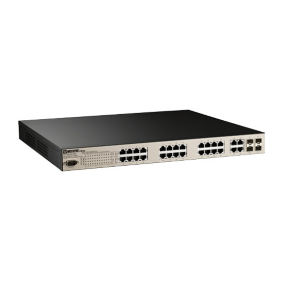
2 Hardware Installation This chapter includes hardware introduction, installation and configuration information. Following topics are covered in this chapter: Hardware Introduction Wiring Power Inputs Power Supply Specifications Wiring Digital Input Wiring Relay Output Wiring Fast Ethernet Ports Wiring Combo Ports Data and Power Ports Wiring RS‐232 console cable 2.10 Rack Mounting Installation 2.11 Safety Warning Hardware Introduction Dimension (H x W x D) is 43.8mm x 431mm x 375mm Diagram: MRI‐128‐F4G‐PSE/24 and MRI‐128‐F4G‐PSE/16 Proudly Distributed by Gross Automation | (877) 268-3700 www.westermosales.com | sales@grossautomation.com... - Page 9 Diagram: MRI‐120‐F4G‐PSE/8 Panel Layout The front panel includes up to 24 10/100Mbps Fast Ethernet ports, 4 combo Gigabit Ethernet ports, SFP slot, RS‐232 console port, System / Combo Port LED and up to 24 PoE LED. Diagram: MRI‐128‐F4G‐PSE/24 and MRI‐128‐F4G‐PSE/16 Diagram: MRI‐120‐F4G‐PSE/8 The back panel consists of 2 DC power inputs, 1 AC Input, 1 Relay Output. 53VDC [p1] Proudly Distributed by Gross Automation | (877) 268-3700 www.westermosales.com | sales@grossautomation.com...
- Page 10 Wiring Power Inputs The switch provides two types power input, AC power input and DC power input. It also provides redundant or aggregated power inputs, depending on the voltage of power input. If there are over two power inputs are connected with different voltages, it will be powered from the highest connected voltage (redundant power). If the voltages of power inputs are the same, the total power output will be aggregated (aggregaged power). ...
- Page 11 Note 1: It is a good practice to turn off input and load power. Otherwise, your screwdriver blade can inadvertently short your terminal connections to the grounded enclosure. Note 2: The range of the suitable electric wire is from 12 to 22 AWG. Note 3: The unit will alarm for loss of power, for instance, PSU, DC1 or DC2. Power Supply Specifications Power Supply Input Range Fuse Max. Power Consumption Type Rating Min Max All Ethernet Ports 48 VDC 46 VDC 57 VDC 10A(T) 280W HI (250 VDC) 127 VDC 370 VDC 4A(T) HI (110/230 90 VAC 264 VAC ...
-
Page 12: Wiring Digital Output
MRI‐120‐F4G‐PSE/8 Power Input Range Fuse Power Consumption Supply Rating Min Max Worst Max Type Case 48 VDC 46 VDC 57 VDC 1.5A(F) 123.2W 123.2W 53 VDC 52 VDC 57 VDC 1.5A(F) 182W 240W Table: PoE/PoE Plus Power Supply Specifications Note 1: (F) Denotes fast‐acting fuse, (T) denotes time‐delay fuse Note 2: Power consumption varies based on configuration. 10/100Tx ports consume roughly 1W less than fiber optic ports ... -
Page 13: Wiring Fast Ethernet Ports
Wiring Fast Ethernet Ports The switch includes up to 24 RJ‐45 Fast Ethernet ports. The Fast Ethernet ports support 10Base‐T and 100Base‐TX, full or half duplex modes. All the Fast Ethernet ports will auto‐detect the signal from connected devices to negotiate the link speed and duplex mode. Auto MDI/MDIX allows users to connect another switch, hub or workstation without changing straight through or crossover cables. ... -
Page 14: Wiring Combo Ports
2 RX – and Vport ‐ 3 TX + and Vport + 6 TX – and Vport + 4, 5, 7, 8 NC Table: RJ45 PoE pin‐out assignment Wiring RS‐232 Console Cable Westermo attaches one RS‐232 DB‐9 to DB‐9 cable in the box. Connect the DB‐9 connector to the COM port of your PC, open Terminal tool and set up serial settings to 9600, N,8,1. (Baud Rate: 9600 / Parity: None / Data Bit: 8 / Stop Bit: 1) Then you can access the CLI interface using the console cable. Proudly Distributed by Gross Automation | (877) 268-3700 www.westermosales.com | sales@grossautomation.com... -
Page 15: Rack Mounting Installation
Note: If you have lost the cable, please contactyour local sales or office or follow the pin assignment to buy/make a new one. The pin assignment spec is listed in the appendix. 2.10 Rack Mounting Installation The Rack Mount Kit is attached inside the package box. Attach the brackets to the device by using the screws provided in the Rack Mount kit. Mount the device in the 19’ rack by using four rack‐mounting screws When installing multiple switches, mount them in the rack one below the other. Proudly Distributed by Gross Automation | (877) 268-3700 www.westermosales.com | sales@grossautomation.com... -
Page 16: Safety Warning
It’s requested to reserve 0.5U‐1U free space for multiple switches installing. This is important to disperse the heat generated by the switch. Notice when installing: Temperature: Check if the rack environment temperature conforms to the specified operating temperature range. Mechanical Loading: Do no place any equipment on top of the switch Grounding: Rack‐mounted equipment should be properly grounded. 2.11 Safety Warning The equipment is intended for installation in a Restricted Access Location. And the below warning will be marked on the equipment in prominent position adjacent to the hot part. Proudly Distributed by Gross Automation | (877) 268-3700 www.westermosales.com | sales@grossautomation.com... -
Page 17: Preparation For Management
Preparation for Serial Console In the package, Westermo attached one RS‐232 DB‐9 to DB‐9 console cable. Please attach RS‐232 DB‐9 connector to your PC COM port, connect to the Console port of the the switch. If you lose/lost the cable, please follow the ... -
Page 18: Preparation For Web Interface
5. Switch to DOS command mode and ping 192.168.2.200 to verify a normal response time. Launch the web browser and Login. 6. Launch the web browser (Internet Explorer or Mozilla Firefox) on the PC. 7. Type http://192.168.2.200 (or the IP address of the switch). And then press Enter. 8. The login screen will appear next. Type in the user name and the password. Default user name is admin and password westermo. Click on Enter or OK. The welcome page of the web‐based management interface will then appear. Proudly Distributed by Gross Automation | (877) 268-3700 www.westermosales.com | sales@grossautomation.com... - Page 19 Note 1: Internet Explorer 5.0 or later versions do not allow Java applets to open sockets by default. Users have to directly modify the browser settings to selectively enable Java applets to use network ports. Note 2: The Web User Interface connection session of the switch will be logged out automatically if you don’t give any input after 30 seconds. After logged out, you should re‐login and type in the correct user name and password again. 3.2.2 Secured Web Interface Westermo web management page also provides secured management HTTPS login. All the configuration commands will be secured. Launch the web browser and Login. Launch the web browser (Internet Explorer or Mozilla Firefox) on the PC. Type https://192.168.2.200 (or the IP address of the switch). And then press Enter. The popup screen will appear and request you to trust the secured HTTPS connection. Press Yes to trust it. ...
-
Page 20: Preparation For Telnet Console
Key in the user name and the password. The default user name is admin and password is westermo. Press Enter or click on OK. The welcome page of the web‐based management interface will then appear. Once you enter the web‐based management interface, all the commands you see are the same as what you see by HTTP login. Preparation for Telnet Console 3.3.1 Telnet The switch supports Telnet console. You can connect to the switch by Telnet and the command lines are the same as what you see by RS232 console port. Below are the steps to open Telnet connection to the switch. 1. Go to Start ‐> Run ‐> cmd. And then press Enter ... - Page 21 After click on Open, then you can see the cipher information in the popup screen. Press Yes to accept the Security Alert. After few seconds, the SSH connection to the switch is opened. Type the Login Name and its Password. The default Login Name and Password are admin / westermo. Proudly Distributed by Gross Automation | (877) 268-3700 www.westermosales.com | sales@grossautomation.com...
- Page 22 All the commands you see in SSH are the same as the CLI commands you see via RS232 console. The next chapter will introduce in detail how to use command line to configure the switch. Proudly Distributed by Gross Automation | (877) 268-3700 www.westermosales.com | sales@grossautomation.com...
-
Page 23: Feature Configuration
4 Feature Configuration This chapter explains how to configure the switch software features. There are four ways to access the switch: Serial console, Telnet/SSH, Web browser and SNMP. Following topics are covered in this chapter: Command Line Interface (CLI) Introduction Basic Setting Port Configuration Power over Ethernet Network Redundancy VLAN Traffic Prioritization Multicast Filtering SNMP 4.10 Security 4.11 Warning 4.12 Monitor and Diag 4.13 Device Front Panel 4.14 Save 4.15 Logout Command Line Interface Introduction The Command Line Interface (CLI) is one of the user interfaces to the switch’s embedded ... - Page 24 Switch> enable Turn on privileged mode command exit Exit current mode and down to previous mode list Print command list ping Send echo messages quit Exit current mode and down to previous mode show Show running system information telnet Open a telnet connection traceroute Trace route to destination ...
- Page 25 Switch# configure terminal Switch(config)# access-list Add an access list entry administrator Administrator account setting Set a static ARP entry clock Configure time-of-day clock default Set a command to its defaults End current mode and change to enable mode exit Exit current mode and down to previous mode gvrp GARP VLAN Registration Protocol hostname...
- Page 26 Switch(config)# interface fa1 Switch(config-if)# acceptable Configure 802.1Q acceptable frame types of a port. auto-negotiation Enable auto-negotiation state of a given port description Interface specific description duplex Specify duplex mode of operation for a port End current mode and change to enable mode exit Exit current mode and down to previous mode flowcontrol...
- Page 27 Summary of the 5 command modes. Command Main Function Enter and Exit Method Prompt Mode User EXEC This is the first level of access. Enter: Login successfully Switch> User can ping, telnet remote Exit: exit to logout. device, and show some basic Next mode: Type enable to information enter privileged EXEC mode. Privileged In this mode, the system allows Enter: Type enable in User Switch# EXEC you to view current EXEC mode. configuration, reset default, Exec: Type disable to exit to reload switch, show system user EXEC mode. information, save Type exit to logout configuration…and enter global Next Mode: Type configure configuration mode. terminal to enter global configuration command. Global In global configuration mode, Enter: Type configure Switch(config)# ...
- Page 28 Here are some useful commands to see available commands. It can save your time when typing and avoid errors. ? To see all the available commands in this mode. It helps you to see the next command you can/should type as well. Switch(config)# interface (?) IFNAME Interface's name vlan Select a vlan to configure (Character)? To see all the available commands starts from this character. Switch(config)# a? access-list Add an access list entry administrator Administrator account setting Set a static ARP entry...
-
Page 29: Basic Setting
Basic Setting The Basic Setting group provides you to configure switch information, IP address, User name/Password of the system. It also allows you to do firmware upgrade, backup and restore configuration, reload factory default, and reboot the system. Following commands are included in this chapter: 4.2.1 Switch Setting 4.2.2 Admin Password 4.2.3 IP Configuration 4.2.4 Time Setting 4.2.5 Jumbo Frame 4.2.6 DHCP Server 4.2.7 Backup and Restore 4.2.8 ... - Page 30 4.2.2 Admin Password You can change the user name and the password here to enhance security. User name: You can type in a new user name here. The default setting is admin. Password: You can type in a new password here. The default setting is westermo. Confirm Password: You need to type the new password again to confirm it. Once you finish configuring the settings, click on Apply to apply your configuration. Figure 4.2.2.2 Popup alert window for Incorrect user name. Proudly Distributed by Gross Automation | (877) 268-3700...
- Page 31 4.2.3 IP Configuration This function allows users to configure the switch’s IP address settings. DHCP Client: You can select to Enable or Disable DHCP Client function. When DHCP Client function is enabled, an IP address will be assigned to the switch from the network’s DHCP server. In this mode, the default IP address will therefore be replaced by the one assigned by DHCP server. If DHCP Client is disabled, then the IP address that you specified will be used instead. IP Address: You can assign the IP address reserved by your network for your switch. If DHCP Client function is enabled, you don’t need to assign an IP address to the switch, as it will be overwritten by DHCP server and shown here. The default IP is 192.168.2.200. ...
- Page 32 4.2.4 Time Setting Time Setting source allow user to set the time manually or via a NTP server. Network Time Protocol (NTP) is used to synchronize computer clocks in a network. You can configure NTP settings here to synchronize the clocks of several switches on the network. It also provides Daylight Saving Time function. Manual Setting: User can select “Manual setting” to change time as user wants. User also can click the button “Get Time from PC” to get PC’s time setting for switch. After click the “Get Time from PC” and apply the setting, the System time display the same time as your PC’s time. ...
- Page 33 Switch(config)# clock timezone 01 (GMT‐12:00) Eniwetok, Kwajalein 02 (GMT‐11:00) Midway Island, Samoa 03 (GMT‐10:00) Hawaii 04 (GMT‐09:00) Alaska 05 (GMT‐08:00) Pacific Time (US & Canada) , Tijuana 06 (GMT‐07:00) Arizona 07 (GMT‐07:00) Mountain Time (US & Canada) 08 (GMT‐06:00) Central America ...
- Page 34 37 (GMT+02:00) Jerusalem 38 (GMT+03:00) Baghdad 39 (GMT+03:00) Kuwait, Riyadh 40 (GMT+03:00) Moscow, St. Petersburg, Volgograd 41 (GMT+03:00) Nairobi 42 (GMT+03:30) Tehran 43 (GMT+04:00) Abu Dhabi, Muscat 44 (GMT+04:00) Baku, Tbilisi, Yerevan ...
- Page 35 Daylight Saving Time: Set when Enable Daylight Saving Time start and end, during the Daylight Saving Time, the device’s time is one hour earlier than the actual time. Once you finish your configuration, click on Apply to apply your configuration. 4.2.5 Jumbo Frame What is Jumbo Frame? The typical Ethernet frame is range from ...
- Page 36 After selecting to enable DHCP Server function, type in the Network IP address for the DHCP server IP pool, Subnet Mask, Default Gateway address and Lease Time for client. Once you have finished the configuration, click Apply to apply your configuration Excluded Address: You can type a specific address into the IP Address field for the DHCP server reserved IP address. The IP address that is listed in the Excluded Address List Table will not be assigned to the network device. Add or remove an IP address from the Excluded Address List by clicking Add or Remove. Manual Binding: the switch provides a MAC address and IP address binding and removing ...
- Page 37 DHCP Relay Agent: The DHCP Relay Agent is also known as DHCP Option 82. It can help relay the DHCP Request to remote DHCP server located in different subnet. Note: The DHCP Server can not work with DHCP Relay Agent at the same time. Relay Agent: Choose Enable or Disable the relay agent. Relay Policy: The Relay Policy is used when the ...
- Page 38 the configuration back to the switch. This mode is only provided by Web UI while CLI is not supported. TFTP Server mode: In this mode, the switch acts as TFTP client. Before you do so, make sure that your TFTP server is ready. Then please type the IP address of TFTP Server and Backup configuration file name. This mode can be used in both CLI and Web UI. TFTP Server IP Address: You need to key in the IP address of your TFTP Server here. Backup/Restore File Name: Please type the correct file name of the configuration file.. ...
- Page 39 Note that the folders of the path to the target file do not allow you to input space key. Type the IP address of TFTP Server IP. Then click on Backup/Restore. Note: point to the wrong file will cause the entire configuration missed 4.2.8 Firmware Upgrade In this section, you can update the latest firmware for your switch. Westermo provides the latest firmware in the Web site. The new firmware may include new features, bug fixes or other software changes. We’ll also provide the release notes for the update as well. For technical viewpoint, we suggest you use the latest firmware before installing the switch to the customer site. Note that the system will be automatically rebooted after you finished upgrading new firmware. Please remind the attached users before you do this. ...
- Page 40 There are two modes for users to backup/restore the configuration file, Local File mode and TFTP Server mode. Local File mode: In this mode, the switch acts as the file server. Users can browse the target folder and then type the file name to backup the configuration. Users also can browse the target folder and select the existed configuration file to restore the configuration back to the switch. This mode is only provided by Web UI while CLI is not supported. TFTP Server mode: In this mode, the switch acts as the TFTP client. Before you do so, make sure that your TFTP server is ready. And then please type the IP address of TFTP Server IP address. This mode can be used in both CLI and Web UI. TFTP Server IP Address: You need to key in the IP address of your TFTP Server here. Firmware File Name: The file name of the new firmware. ...
- Page 41 4.2.9 Factory Default In this section, you can reset all the configurations of the switch to default setting. Click on Reset the system will then reset all configurations to default setting. The system will show you popup message window after finishing this command. Default setting will work after rebooting the switch. Popup alert screen to confirm the command. Click on Yes to start it. Click on OK to close the screen. Then please go to Reboot page to reboot the switch. Click on OK. The system will then auto reboot the device. Note: If you already configured the IP of your device to other IP address, when you use this command by CLI and Web UI, the switch will not reset the IP address to default IP. The system will remain the IP address so that you can still connect the ...
- Page 42 WORD Network name of this system Switch(config)# hostname SWITCH SWITCH(config)# System SWITCH(config)# snmp-server location Sweden Location System Contact SWITCH(config)# snmp-server contact support@westermo.se Display SWITCH# show snmp-server name SWITCH SWITCH# show snmp-server location Sweden SWITCH# show snmp-server contact support@westermo.se Proudly Distributed by Gross Automation | (877) 268-3700...
- Page 43 Switch> show version Loader Version : 1.0.0.3 Firmware Version : 1.1.26-20101025-10:17:48 Switch# show hardware mac MAC Address : 00:07:7c:e6:00:00 Switch# show hardware led RM : Off Admin Password User Name and SWITCH(config)# administrator Password NAME Administrator account name SWITCH(config)# administrator orwell PASSWORD Administrator account password SWITCH(config)# administrator orwell orwell Change administrator account orwell and password...
- Page 44 inet 192.168.2.8/24 broadcast 192.168.2.255 ……….. SWITCH# show running-config ……… interface vlan1 ip address 192.168.2.8/24 no shutdown ip route 0.0.0.0/0 192.168.2.254/24 Time Setting NTP Server SWITCH(config)# ntp peer enable disable primary secondary SWITCH(config)# ntp peer primary IPADDR SWITCH(config)# ntp peer primary 192.168.2.200 Time Zone SWITCH(config)# clock timezone 26 Sun Jan 1 04:13:24 2006 (GMT) Greenwich Mean Time:...
- Page 45 Secondary peer : N/A SWITCH# show clock Sun Jan 1 04:14:19 2006 (GMT) Greenwich Mean Time: Dublin, Edinburgh, Lisbon, London SWITCH# show clock timezone clock timezone (26) (GMT) Greenwich Mean Time: Dublin, Edinburgh, Lisbon, London Switch# show ptpd PTPd is enabled Mode: Slave Jumbo Frame Jumbo Frame...
- Page 46 lease DHCP Lease Time list Print command list network dhcp network remove quit Exit current mode and down to previous mode service enable service DHCP Server Switch(config-dhcp)# service dhcp Enable <cr> DHCP Server IP Switch(config-dhcp)# network Pool A.B.C.D/M network/mask ex. 10.10.1.0/24 (Network/Mask Switch(config-dhcp)# network 192.168.2.0/24 DHCP Server –...
- Page 47 replace Switch(config-dhcp)# ip dhcp relay information policy drop <cr> Switch(config-dhcp)# ip dhcp relay information policy keep <cr> Switch(config-dhcp)# ip dhcp relay information policy replace <cr> DHCP Relay – IP Switch(config-dhcp)# ip dhcp helper-address Helper Address A.B.C.D Switch(config-dhcp)# ip dhcp helper-address 192.168.2.200 Reset DHCP Switch(config-dhcp)# ip dhcp reset...
- Page 48 DHCP Relay Switch# show ip dhcp relay Information DHCP Relay Agent ON ---------------------------------------- IP helper-address : 192.168.2.200 Re-forwarding policy: Replace Backup and Restore Backup Startup Switch# copy startup-config tftp: Configuration 192.168.2.33/default.conf file Writing Configuration [OK] Note 1: To backup the latest startup configuration file, you should save current settings to flash first.
- Page 49 Firmware Upgrade Firmware Switch# archive download-sw /overwrite tftp Upgrade 192.168.2.33 MRI-128-F4G-PSE.bin Firmware upgrading, don't turn off the switch! Tftping file MRI-128-F4G-PSE.bin Firmware upgrading ......................................Firmware upgrade success!! Rebooting..Factory Default Factory Switch# reload default-config file Default Reload OK! Switch# reboot System Reboot...
-
Page 50: Port Configuration
Port Configuration Port Configuration group enables you to enable/disable port state, or configure port auto‐negotiation, speed, and duplex, flow control, rate limit control and port aggregation settings. It also allows you to view port status and aggregation information. Following commands are included in this chapter: 4.3.1 Port Control 4.3.2 Port Status 4.3.3 Rate Control 4.3.4 Storm Control 4.3.5 ... - Page 51 In Speed/Duplex column, you can configure port speed and duplex mode of this port. Below are the selections you can choose: Fast Ethernet Port 1~24 (fa1~fa24): AutoNegotiation, 10M Full Duplex(10 Full), 10M Half Duplex(10 Half), 100M Full Duplex(100 Full) and 100M Half Duplex(100 Half). Gigabit Ethernet Port 25~28: (gi25~gi28): AutoNegotiation, 10M Full Duplex(10 Full), 10M Half Duplex(10 Half), 100M Full Duplex(100 Full), 100M Half Duplex(100 Half), 1000M Full Duplex(1000 Full), 1000M Half Duplex(1000 Half). The default mode is Auto Negotiation mode. In Flow Control column, “Symmetric” means that you need to activate the flow control function of the remote network device in order to let the flow control of that corresponding port on the switch to work. “Disable” means that you don’t need to activate the flow control function of the remote network device, as the flow control of that corresponding port on the switch will work anyway. ...
- Page 52 The description of the columns is as below: Port: Port interface number. Type: 100TX ‐> Fast Ethernet port. 1000TX ‐> Gigabit Ethernet port. Link: Link status. Up ‐> Link UP. Down ‐> Link Down. State: Enable ‐> State is enabled. Disable ‐> The port is disable/shutdown. Speed/Duplex: Current working status of the port. Flow Control: The state of the flow control. SFP Vendor: Vendor name of the SFP transceiver you plugged. Wavelength: The wave length of the SFP transceiver you plugged. Distance: The distance of the SFP transceiver you plugged. Eject: Eject the DDM SFP transceiver. You can eject one port or eject all by click the icon “Eject All”. Temperature: The temperature specific and current detected of DDM SFP transceiver. Tx Power (dBm): The specification and current transmit power of DDM SFP transceiver. Rx Power (dBm): The specification and current received power of DDM SFP transceiver. ...
- Page 53 2. If the plugged DDM SFP transceiver is not certified by Westermo, the DDM function will not be supported. But the communication will not be disabled. 4.3.3 Rate Control Rate limiting is a form of flow control used to enforce a strict bandwidth limit at a port. You can program separate transmit (Egress Rule) and receive (Ingress Rule) rate limits at each port, and even apply the limit to certain packet types as described below. ...
- Page 54 Packet type: You can assign the Rate for specific packet types based on packet number per second. The packet types of the Ingress Rule listed here include Broadcast, DLF (Destination Lookup Failure) and Multicast. Choose Enable/Disable to enable or disable the storm control of specific port. Rate: This column allows you to manually assign the limit rate of the port. The unit is packets per second. The limit range is from 1 to 262143 packet/sec, zero ...
- Page 55 Link Aggregation Group (LAG), Link Aggregation Control Protocol, Ethernet Trunk, Ether Channel…etc. Most of the implementations now conform to IEEE standard, 802.3ad. The aggregated ports can interconnect to the other switch which also supports Port Trunking. Westermo Supports two2 types of port trunking. One is Static Trunk, the other is 802.3ad. When the other end uses 802.3ad LACP, you should assign 802.3ad LACP to the trunk. When the other end uses non‐802.3ad, you can then use Static Trunk. There are two configuration pages, Aggregation Setting and Aggregation Status. ...
- Page 56 Aggregation Status This page shows the status of port aggregation. Once the aggregation ports are negotiated well, you will see following status. Group ID: Display Trunk 1 to Trunk 8 set up in Aggregation Setting. Type: Static or LACP set up in Aggregation Setting. Aggregated Ports: When the LACP links is up, you can see the member ports in Aggregated column. Individual Ports: When LACP is enabled, member ports of LACP group which are not connected to correct LACP member ports will be displayed in the Individual column. Link Down Ports: When LACP is enabled, member ports of LACP group which are not linked up will be displayed in the Link Down column. Load Balance: There is several load balance types based on dst‐ip (Destination IP), dst‐mac (Destination MAC), src‐dst‐ip (Source and Destination IP), src‐dst‐mac (Source and Destination MAC), src‐ip (Source IP), src‐mac (Source MAC). Proudly Distributed by Gross Automation | (877) 268-3700 www.westermosales.com | sales@grossautomation.com...
- Page 57 4.3.6 Command Lines for Port Configuration Feature Command Line Port Control Port Switch(config-if)# shutdown -> Disable port Control – state State Port1 Link Change to DOWN interface fastethernet1 is shutdown now. Switch(config-if)# no shutdown -> Enable port state Port1 Link Change to DOWN Port1 Link Change to UP interface fastethernet1 is up now.
- Page 58 Control – Port1 Link Change to DOWN Force set the speed mode ok! Speed/Duple Switch(config-if)# Port1 Link Change to UP Switch(config-if)# duplex full Port1 Link Change to DOWN set the duplex mode ok! Switch(config-if)# Port1 Link Change to UP Port Switch(config-if)# flowcontrol on Control –...
- Page 59 Rx power:N/A Port 9 Temperature:64.00 C <range :0.0-80.00> Tx power:-6.0 dBm <range : -9.0 - -4.0> Rx power:-30.0 dBm <range: -30.0 - -4.0> Port 10 Temperature:67.00 C <range :0.0-80.00> Tx power:-6.0 dBm <range : -9.0 - -4.0> Rx power:-2.0 dBm <range: -30.0 - -4.0> Note: Administrative Status ->...
- Page 60 Packet Type dlf :Destination Lookup Failure multicast :Multicast packets Storm Switch(config)# storm-control broadcast Contr–l - <0-100000> Rate limit value 0~262143 packet/sec Rate Switch(config)# storm-control broadcast 10000 limit_rate = 10000 packets/sec Set rate limit for Broadcast packets. Switch(config)# storm-control multicast 10000 limit_rate = 10000 packets/sec Set rate limit for Multicast packets.
-
Page 61: Power Over Ethernet
GroupID Protocol Ports --------+---------+--------------------------------- LACP 8(D) 9(D) 10(D) Switch# show trunk group 2 FLAGS: I -> Individual P -> In channel D -> Port Down Trunk Group GroupID Protocol Ports --------+---------+--------------------------------- Static 6(D) 7(P) Switch# Power over Ethernet Power over Ethernet is one of the key features of the switch. It is fully IEEE802.3af‐2003 ... - Page 62 As shown in the above picture, you can enable/disable the PoE function and configure the power budget and voltage of DC Power 1 and DC Power 2. The valid range of budget is 0 – 400 Watts (default is 0, and 0 mean power is disable). The valid range of power voltage is 46 ‐ 57 V (default is 53 V). And the default power budget of inside AC power supply is 300 Watts and 53 V. Warning Water Level is used for power utiltization monitoring, (valid range is 0 – 100 %, and 0 mean function is disable) If the power utilization using is more than this water level, the warning event will happen. Pull down the PoE Mode column to enable/disable ports, or set it to scheduling control mode. Pull ...
- Page 63 IEEE 802.3at LLDP provides smart power budget control behavior to fulfill the needs of higher end setups requiring exact high power delivery. By using the ongoing dynamic re‐negotiation function of the IEEE802.3at LLDP, the switch can perform more intelligently by dynamically reallocating power to the PDs. The switch implements the 2‐event and Link Layer Discovery Protocol (LLDP) PoE into the system for efficient power budget negotiation between PSE and PD devices. The Power Budget can limit the consumption of PoE port and ensure the ...
- Page 64 4.4.2 Emergency Power Management The switch is equipped with dual 48VDC power inputs for providing true network redundancy. An alarm relay output signals when a power input fails or other critical events occur. To ensure reliable power delivery, other advanced PoE power management features include individual port status monitoring, emergency power management (3 power supply indication inputs for quick shutdown of ports according to pre‐defined priority table in cases where power ...
- Page 65 that you want to detect. The Cycle Time is the gap per detection. After configuring, please click the Apply button to enable and perform the functions. 4.4.4 PoE Scheduling The PoE Scheduling control is a powerful function which helps you to save power and money. You need to configure PoE Scheduling and select a target port manually to enable this function. 4.4.5 PoE Status The PoE Status page shows the operating status of each power and each PoE Port. The power information includes power input voltage,budget, power aggregation, redundancy status, Total Power budget, Total Output Power, Warning Water Level ...
- Page 66 power will be backup power for primary. The tertiary power will be backup power for primary or secondary. 4.4.6 Command Line for PoE control Syntax show poe system Parameters Enable mode Command Mode Description Display the status of the PoE system. Examples Switch> enable Switch# show poe system PoE System PoE Admin : Enable PoE Hardward : Normal PoE Input Voltage : Vmain 1 : 52.8 V Vmain 2 : 53.0 V...
- Page 67 Ouput power : 0.0 Watts Temperature 1 : 39 degree Temperature 2 : 41 degree Temperature 3 : 47 degree Power information : Budget : DC Power 1 : 400 Watts (In Use) DC Power 2 : 400 Watts AC Power : 300 Watts (In Use) Total : 1100 Watts 700 Watts in Use Warning water level : N/A...
- Page 68 Switch# show poe pd-detect Examples PD Status Detection Status : Enabled Host 1 : Target IP : 192.168.2.100 Cycle Time : 10 Host 2 : Target IP : 192.168.2.200 Cycle Time : 20 Host 3 : Target IP : 192.168.2.15 Cycle Time : 30 Host 4 : Target IP : 192.168.2.20...
- Page 69 Syntax poe powering-mode 802.3af/forced Parameters 802.3af: deliver power if and only if the attached PD comply with IEEE 802.3af forced: deliver power no maater what PD attached Command Mode Interface mode Description Set the Powring mode of PoE EX 1: Set 802.3af powring mode Examples Switch(config)# poe powering-mode 802.3af EX 2: Set forced powering mode...
- Page 70 Syntax poe user enable/disable Parameters enable: enable port in user mode disable: disable port in user mode Command Mode Interface mode Description Enable/Disable the PoE of the port in user mode. If in schedule mode, it will come into affect when the control mode changes to user mode.
- Page 71 Syntax poe priority critical/high/low Parameters Critical : Hightest priority level High : High priority level Low : Low priority level Command Mode Interface mode Description Set the powering priority. The port with higher priority will have the privilege to delivery power under limited power situation.
- Page 72 Syntax poe budget warning <0-100> Parameters <0-100> 0 is disable, valid range is 1 to 100 percentage Command Mode Configuration mode Description Set the warning water level of total power budget. Set the warning water level to 60% Examples Switch(config-if)# poe budget warning 60 Syntax poe pd_detect enable/disable Parameters...
-
Page 73: Network Redundancy
Network Redundancy The switch firmware supports standard RSTP, Multiple Super Ring, Rapid Dual Homing. Multiple Super Ring (MSR) technology, 0 milliseconds for restore and less than 300 milliseconds for failover. Advanced Rapid Dual Homing (RDH) technology also facilitates the switch to connect with a core managed switch easily and conveniently. With RDH technology, you can also group several Rapid Super Rings or RSTP cloud together, which is also known as Auto Ring Coupling. Besides ring technology, the switch also supports 802.1D‐2004 version Rapid Spanning Tree Protocol (RSTP). New version of RSTP standard includes 802.1D‐1998 ... - Page 74 RSTP Mode: You must first enable STP/RSTP mode, before configuring any related parameters. Parameter settings required for both STP and RSTP are the same. Note that 802.1d refers to STP mode, while 802.1w refers to faster RSTP mode. Bridge Configuration Priority (0‐61440): RSTP uses bridge ID to determine the root bridge, the bridge with the highest bridge ID becomes the root bridge. The bridge ID is composed of bridge priority and bridge MAC address. So that the bridge with the highest priority becomes the highest bridge ID. If all the bridge ID has the same priority, the bridge with the lowest MAC address will then become the root bridge. Note: The bridge priority value must be in multiples of 4096. A device with a lower number has a higher bridge priority. Ex: 4096 is higher than 32768. ...
- Page 75 reconfigure itself as a root bridge. Once two or more devices on the network are recognized as a root bridge, the devices will renegotiate to set up a new spanning tree topology. Hello Time (1‐10): Enter a value from 1 to 10 seconds here. This is a periodic timer that drives the switch to send out BPDU (Bridge Protocol Data Unit) packet to check current STP status. The root bridge of the spanning tree topology periodically sends out a “hello” message to other devices on the network to check if the topology is “healthy”. The “hello time” is the amount of time the root has waited during sending hello ...
- Page 76 Admin Edge: A port directly connected to the end stations cannot create a bridging loop in the network. To configure this port as an edge port, set the port to the Enable state. When the non‐bridge device connects an admin edge port, this port will be in blocking state and turn to forwarding state in 4 seconds. Once you finish your configuration, click on Apply to save your settings. 4.5.2 RSTP Info This page allows you to see the information of the root switch and port status. Root Information: You can see root Bridge ID, Root Priority, Root Port, Root Path Cost and the Max Age, Hello Time and Forward Delay of BPDU sent from the root switch. Port Information: You can see port Role, Port State, Path Cost, Port Priority, Oper P2P mode, Oper edge port mode and Aggregated(ID/Type). 4.5.3 Multiple Super Ring (MSR) The most common industrial network redundancy is to form a ring or loop. Typically, ...
- Page 77 The Multiple Super Ring has enhanced Ring Master selection and faster recovery time. It is also enhanced for more complex ring application. Multiple Super Ring (MSR) technology ranks the fastest restore and failover time in the world, 0 ms for restore and less than 300 ms for failover. Advanced Rapid Dual Homing (RDH) technology also facilitates Switch Managed Switch to connect with a core managed switch easily and conveniently. With RDH technology, you can also couple several Rapid Super Rings or RSTP cloud together, which is also known as Auto Ring Coupling. TrunkRing technology allows integrate MSR with LACP/Port Trunking. The LACP/Trunk aggregated ports is a virtual interface and it can work as the Ring port of the MSR. MultiRing is an outstanding technology that multiple rings can be aggregated within one switch by using different Ring ID. The maximum Ring number one switch can support is half of total port volume. For example, the switch is a 24+4G ...
- Page 78 Ring Configuration ID: Once a Ring is created, it appears and can not be changed. In multiple rings’ environment, the traffic can only be forwarded under the same ring ID. Name: This field will show the name of the Ring. If it is not filled in when creating, it will be automatically named by the rule “RingID”. Version: The version of Ring can be changed here. There are three modes to choose: Rapid Super Ring as default. Device Priority: The switch with highest priority (highest value) will be automatically selected as Ring Master. Then one of the ring ports in this switch will become forwarding port and the other one will become blocking port. If all of ...
- Page 79 4.5.4 Ring Info This page shows the RSR information. ID: Ring ID. Version: which version of this ring. Role: This Switch is RM or nonRM Status: If this field is Normal which means the redundancy is activated. If any one of the links in the Ring is down, then the status will be Abnormal. RM MAC: The MAC address of Ring Master of this Ring. It helps to find the redundant path. Blocking Port: This field shows which is blocked port of RM. Role Transition Count: This shows how many times this switch has changed its Role from nonRM to RM or from RM to nonRM. ...
- Page 80 4.5.5 Command Lines: Feature Command Line RSTP Enable Switch(config)# spanning-tree enable Disable Switch (config)# spanning-tree disable RSTP mode Switch(config)# spanning-tree mode rapid-stp SpanningTree Mode change to be RSTP(802.1w) . STP mode Switch(config)# spanning-tree mode stp SpanningTree Mode change to be STP(802.1d) . Priority Switch(config)# spanning-tree priority <0-61440>...
- Page 81 RSTP Info Active status Switch# show spanning-tree active Rapid Spanning-Tree feature Enabled Spanning-Tree BPDU transmission-limit Root Address 0007.7c01.0386 Priority 4096 Root Path Cost : 200000 Root Port : 7 Root Times : max-age 20 sec, hello-time 2 sec, forward-delay 15 sec Bridge Address 0007.7cff.0102 Priority 4096...
- Page 82 Port 128.6 as Disabled Role is in Disabled State Port Path Cost 200000, Port Identifier 128.6 RSTP Port Admin Link-Type is Auto, Oper Link-Type is Point-to-Point RSTP Port Admin Edge-Port is Enabled, Oper Edge-Port is Edge Designated root has priority 32768, address 0007.7c00.0112 Designated bridge has priority 32768, address 0007.7c60.1aec...
- Page 83 Ring Port Switch(config-multiple-super-ring)# port IFLIST Interface list, ex: fa1,fa3-5,gi8-10 cost path cost Switch(config-multiple-super-ring)# port fa1,fa2 Ring Port Cost Switch(config-multiple-super-ring)# port cost <0-255> valid range is 0 or 255 default set default (128)valid range is 0 or 255 Switch(config-multiple-super-ring)# port cost 100 <0-255>...
- Page 84 Ring Info Ring Info Switch# show multiple-super-ring [Ring ID] [Ring1] Ring1 Current Status : Disabled Role : Disabled Ring Status : Abnormal Ring Manager : 0000.0000.0000 Blocking Port : N/A Giga Copper : N/A Configuration : Version : Rapid Super Ring Priority : 128 Ring Port...
-
Page 85: Vlan
VLAN A Virtual LAN (VLAN) is a “logical” grouping of nodes for the purpose of limiting a broadcast domain to specific members of a group without physically grouping the members together. That means, VLAN allows you to isolate network traffic so that only members of VLAN could receive traffic from the same VLAN members. Basically, creating a VLAN from a switch is the logical equivalent of physically reconnecting a group of network devices to another Layer 2 switch, without actually disconnecting these devices from their original switches. ... - Page 86 PVID: The abbreviation of the Port VLAN ID. Enter the port VLAN ID. PVID allows the switches to identify which port belongs to which VLAN. To keep things simple, it is recommended that PVID is equivalent to VLAN IDs. The values of PVIDs are from 0 to 4095. But, 0 and 4095 are reserved. You can’t input these two PVIDs and 1 is the default value and 2 to 4094 are valid and available. Accept Frame Type: This column defines the accepted frame type of the port. There are two modes you can select, Admit All and Tag Only. Admit All mode means that the port can accept both tagged and untagged packets. Tag Only mode means that the port can only accept tagged packets. ...
- Page 87 Management VLAN ID: The switch supports management VLAN. The management VLAN ID is the VLAN ID of the CPU interface so that only member ports of the management VLAN can access the switch. The default management VLAN ID is 1. Static VLAN: You can assign a VLAN ID and VLAN Name for new VLAN here. VLAN ID is used by the switch to identify different VLANs. Valid VLAN ID is between 1 and 4094 andVLAN 1 is the default VLAN. VLAN Name is a reference for network administrator to identify different VLANs. The available character is 12 for you to input. If you don’t input VLAN name, the system will automatically assign VLAN name for the VLAN. The rule is VLAN (VLAN ID). ...
- Page 88 Static VLAN Configuration You can see the created VLANs and specify the egress (outgoing) port rule to be Untagged or Tagged . Static VLAN Configuration table. You can see that new VLAN 3 is created. VLAN name is test. Egress rules of the ports are not configured now. ‐‐ : Not available U: Untag: Indicates that egress/outgoing frames are not VLAN tagged. T : Tag: Indicates that egress/outgoing frames are to be VLAN tagged. Steps to configure Egress rules: Select the VLAN ID. Entry of the selected VLAN turns to light blue. Assign Egress rule of the ports to U or T. Press Apply to apply the setting. If you want to remove one VLAN, select the VLAN entry. Then press Remove button. Proudly Distributed by Gross Automation | (877) 268-3700 www.westermosales.com | sales@grossautomation.com...
- Page 89 4.6.3 GVRP configuration GVRP allows users to set‐up VLANs automatically rather than manual configuration on every port of every switch in the network. GVRP Protocol: Allow user to enable/disable GVRP globally. State: After enable GVRP globally, here still can enable/disable GVRP by port. Join Timer: Controls the interval of sending the GVRP Join BPDU.An instance of this timer is required on a per‐Port, per‐GARP Participant basis. Leave Timer: Control the time to release the GVRP reservation after received the GVRP Leave BPDU. An instance of the timer is required for each state machine that is in the LV state. ...
- Page 90 VLAN ID: ID of the VLAN. Name: Name of the VLAN. Status: Static shows this is a manually configured static VLAN. Unused means this VLAN is created by UI/CLI and has no member ports. This VLAN is not workable yet. Dynamic means this VLAN is learnt by GVRP. After created the VLAN, the status of this VLAN will remain in Unused status until you add ports to the VLAN. 4.6.5 CLI Commands of the VLAN Command Lines of the VLAN port configuration, VLAN configuration and VLAN table display Feature Command Line VLAN Port Configuration VLAN Port PVID Switch(config-if)# switchport trunk native vlan 2 Set port default vlan id to 2 success Port Accept Frame Switch(config)# inter fa1...
- Page 91 Ingress Filtering Switch(config)# interface fa1 (for fast Ethernet Switch(config-if)# ingress filtering enable port 1) ingress filtering enable Switch(config-if)# ingress filtering disable ingress filtering disable Egress rule – Switch(config-if)# switchport access vlan 2 Untagged (for VLAN switchport access vl–n - success Egress rule –...
- Page 92 no shutdown VLAN Configuration Create VLAN (2) Switch(config)# vlan 2 vlan 2 success Switch(config)# interface vlan 2 Switch(config-if)# Note: In CLI configuration, you should create a VLAN interface first. Then you can start to add/remove ports. Default status of the created VLAN is unused until you add member ports to it.
- Page 93 192.168.2.200/24 ->Delete the IP address Create multiple Switch(config)# interface vlan 5-10 VLANs (VLAN 5-10) Shut down VLAN Switch(config)# interface vlan 2 Switch(config-if)# shutdown Switch(config-if)# no shutdown ->Turn on the VLAN Display – VLAN Switch# sh vlan table VLAN Name Status Trunk Ports Access Ports ---- ------------ -------...
- Page 94 GVRP configuration GVRP Switch(config)# gvrp mode enable/disable disable Disable GVRP feature globally on the switch enable Enable GVRP feature globally on the switch Switch(config)# gvrp mode enable Gvrp is enabled on the switch! Switch(config)# inter fa1 Configure GVRP timer Switch(config-if)# garp timer <10-10000>...
-
Page 95: Traffic Prioritization
Traffic Prioritization Quality of Service (QoS) provides traffic prioritization mechanism and can also help to alleviate congestion problems and ensure high‐priority traffic is delivered first. This section allows you to configure Traffic Prioritization settings for each port with regard to setting priorities. QOS supports four physical queues, weighted fair queuing (WRR) and Strict Priority scheme, which follows 802.1p COS tag and IPv4 TOS/DiffServ information to prioritize the traffic of your industrial network. Following commands are included in this chapter: ... - Page 96 Use a Round Robin scheme. The Round Robin scheme means all the priority has the same privilege, the traffic is forward cyclic from highest to lowest. Use a strict priority scheme. Packets with higher priority in the queue will always be processed first, except that there is no packet with higher priority. Use Weighted Round Robin scheme. This scheme allows users to assign new weight ratio for each class. The 10 is the highest ratio. The ratio of each class is as below: Wx / W0 + W1 + W2 + W3 + W4 + W5 + W6 + W7 (Total volume of Queue 0‐7) Port Setting Priority column is to indicate default port priority value for untagged or priority‐tagged frames. When the switch receives the frames, the switch will attach the value to the CoS field of the incoming VLAN‐tagged packets. You can ...
- Page 97 After configuration, press Apply to enable the settings. 4.7.4 CLI Commands of the Traffic Prioritization Command Lines of the Traffic Prioritization configuration Feature Command Line QoS Setting Queue Scheduling – Switch(config)# qos queue-sched Round Robin Round Robin Strict Priority wrr Weighted Round Robin Switch(config)# qos queue-sched rr The queue scheduling scheme is setting to Round Robin.
- Page 98 The queue scheduling scheme is setting to Weighted Round Robin. Port Setting – Switch(config)# interface fa1 Priority Switch(config-if)# qos priority DEFAULT-PRIORITY Assign an priority (7 highest) Switch(config-if)# qos priority 7 The default port priority value is set 7 ok. Note: When change the port setting, you should Select the specific port first.
- Page 99 Map CoS 1 to Queue Switch(config)# qos cos-map 1 1 The CoS to queue mapping is set ok. Map CoS 2 to Queue Switch(config)# qos cos-map 2 2 The CoS to queue mapping is set ok. Map CoS 3 to Queue Switch(config)# qos cos-map 3 3 The CoS to queue mapping is set ok.
- Page 100 DSCP-Queue Mapping Format Switch(config)# qos dscp-map PRIORITY Assign an priority (63 highest) Switch(config)# qos dscp-map 0 QUEUE Assign an queue (0-7) Format: qos dscp-map priority_value queue_value Map DSCP 0 to Queue Switch(config)# qos dscp-map 0 1 The TOS/DSCP to queue mapping is set ok. Display –...
-
Page 101: Multicast Filtering
Multicast Filtering For multicast filtering, the switch uses IGMP Snooping technology. IGMP (Internet Group Management Protocol) is an Internet Protocol that provides a way for internet device to report its multicast group membership to adjacent routers. Multicasting allows one computer on the internet to send data to a multitude of other computers that have identified themselves as being interested ... - Page 102 Following commands are included in this section: 4.8.2 IGMP Query 4.8.3 Unknown Multicast 4.8.4 CLI Commands of the Multicast Filtering 4.8.1 IGMP Snooping This page is to enable IGMP Snooping feature, assign IGMP Snooping for specific VLAN, and view IGMP Snooping table from dynamic learnt or static manual key‐in. The switch support IGMP snooping V1/V2/V3 automatically and IGMP query V1/V2. IGMP Snooping, you can select Enable or Disable here. After enabling IGMP Snooping, you can then enable IGMP Snooping for specific VLAN. You can enable ...
- Page 103 IGMP Snooping Table: In the table, you can see multicast group IP address, VLAN ID it belongs to, and member ports of the multicast group. The switch supports 256 multicast groups. Click on Reload to refresh the table. Proudly Distributed by Gross Automation | (877) 268-3700 www.westermosales.com | sales@grossautomation.com...
- Page 104 4.8.2 IGMP Query This page allows users to configure IGMP Query feature. Since the switch can only be configured by member ports of the management VLAN, IGMP Query can only be enabled on the management VLAN. If you want to run IGMP Snooping feature in several VLANs, you should notice that whether each VLAN has its own IGMP Querier first. The IGMP querier periodically sends query packets to all end‐stations on the LANs or VLANs that are connected to it. For networks with more than one IGMP ...
- Page 105 Send to Query Ports: The unknown multicast will be sent to the Query ports. The Query port means the port received the IGMP Query packets andit is usually the uplink port on the switch. Send to All Ports: The unknown multicast will be flooded to all ports even if they are not member ports of the groups. Discard: The unknown multicast will be discarded. Non‐member ports will not receive the unknown multicast streams. 4.8.4 CLI Commands of the Multicast Filtering Command Lines of the multicast filtering configuration Feature Command Line IGMP Snooping IGMP Snooping - Switch(config)# ip igmp snooping Global IGMP snooping is enabled globally. Please specify on which vlans IGMP snooping enables IGMP Snooping - Switch(config)# ip igmp snooping vlan...
- Page 106 query-interval; 125s query-max-response-time: 10s Switc evic ip igmp snooping IGMP snooping is globally enabled Vlan1 is IGMP snooping enabled Vlan2 is IGMP snooping enabled Vlan3 is IGMP snooping disabled Display – IGMP Switc evic ip igmp snooping multicast all Table VLAN IP Address Type...
- Page 107 interface vlan1 ip address 192.168.2.200/24 ip igmp no shutdown ……. Unknown Multicast Send Unknown Switch(config)# ip igmp snooping Multicast to Query source-only-learning Ports IGMP Snooping Source-Only-Learning enabled Switch(config)# no ip igmp snooping Send Unknown source-only-learning Multicast to All IGMP Snooping Source-Only-Learning disabled Ports Switch(config)# no mac-address-table multicast filtering...
-
Page 108: Snmp
SNMP Simple Network Management Protocol (SNMP) is a protocol used for exchanging management information between network devices and is a member of the TCP/IP protocol suite. The switch support SNMP v1 and v2c and V3. An SNMP managed network consists of two main components: agents and a manager. An agent is a management software module that resides in a managed switch. An agent translates the local management information from the managed device into a SNMP compatible format. The manager is the console through the network. Following commands are included in this chapter: 4.9.1 SNMP Configuration 4.9.2 SNMPv3 Profile 4.9.3 SNMP Traps 4.9.4 ... - Page 109 4.9.2 SNMP V3 Profile SNMP V3 can provide more security functions when the user performs remote management through SNMP protocol. It delivers SNMP information to the administrator with user authentication; all of data between the switch and the administrator are encrypted to ensure secure communication. Security ...
- Page 110 SNMP Trap is the notification feature defined by SNMP protocol. All the SNMP management applications can understand such trap information. So you don’t need to install new application to read the notification information. This page allows users to Enable SNMP Trap, configure the SNMP Trap server IP, Community name, and trap Version V1 or V2. After configuration, you can see the change of the SNMP pre‐defined standard traps and Westermo pre‐defined traps. The pre‐defined traps can be found in Westermo private MIB. Proudly Distributed by Gross Automation | (877) 268-3700...
- Page 111 4.9.4 CLI Commands of the SNMP Command Lines of the SNMP configuration Feature Command Line SNMP Community Read Only Switch(config)# snmp-server community public ro Community community string add ok Read Write Switch(config)# snmp-server community private Community community string add ok SNMP Trap Enable Trap Switch(config)# snmp-server enable trap Set SNMP trap enable ok. SNMP Trap Server IP Switch(config)# snmp-server host 192.168.2.33 without specific...
-
Page 112: Security
4.10 Security The switch provides several security features for you to secure your connection. The Filter Set is also known as Access Control List. The ACL feature includes traditional Port Security and IP Security. Following commands are included in this section: 4.10.1 Filter Set (Access Control List) 4.10.2 IEEE 802.1x 4.10.3 CLI Commands of the Security 4.10.1 Filter Set (Access Control List) The Filter Set is known as Access Control List feature. There are two major types, one is MAC Filter and the other one is IP Filter. ACE is short of Access Control Entry, user defines the Permit or Deny rule for specific IP/MAC address or IP groups by network mask in each ACE. One ACL may ... - Page 113 MAC Filter (Port Security): The MAC Filter allows user to define the Access Control List for specific MAC address or a group of MAC addresses. Filter ID/Name: The name for this MAC Filter entry. Action: Permit to permit traffic from specified sources. Deny to deny traffic from those sources. Source/Destination Address: Type the MAC address you want configure, the format is “AABB.CCDD.EEFF”. Example: “Source to Destination” is “0007.7c00.0000 to 0007.7c00.0002”. Source/Destination Wildcard: This command allows user to define single host or a group of hosts based on the wildcard. Some of the allowance examples are as ...
- Page 114 Egress Port: Bind the MAC Filter rule to specific front port. Once you finish configuring the ACE settings, click on Add to apply your configuration. You can see below screen is shown. Example of the below Entry: Permit Source MAC “0007.7c00.0000” to Destination MAC “0007.7c00.0002”. The Permit rule is egress rule and it is bind to Gigabit Ethernet Port 25. Once you finish configuring the settings, click on Apply to apply your configuration. Proudly Distributed by Gross Automation | (877) 268-3700 www.westermosales.com | sales@grossautomation.com...
- Page 115 IP Filter: Type ID/Name when select IP Filter. The ID for IP access list is listed as below of the field. You can also type ACL name in this field, it goes to IP Extended mode setting and support both IP Standard and IP Extended mode depend on the setting. Click Add to add the rule. Click Edit to edit the content for the rule. After configured, click Apply to apply all the rules. Reload to reload setting. Remove to remove one of the entries. Example: IP Standard Access List: This kind of ACL allows user to define filter rules according to the source IP address. IP Extended Access List: This kind of ACL allows user to define filter rules according to the source IP address, destination IP address, Source TCP/UDP port, ...
- Page 116 Filter ID/Name: The ID or the name for this IP Filter entry. Action: Permit to permit traffic from specified sources. Deny to deny traffic from those sources. Source/Destination Address: Type the source/destination IP address you want configure. Source/Destination Wildcard: This command allows user to define single host or a group of hosts based on the wildcard. Some of the allowance examples are as below: Proudly Distributed by Gross Automation | (877) 268-3700 www.westermosales.com | sales@grossautomation.com...
- Page 117 Wildcard Bit Number of Note allowance Any 11111111.11111111. All All IP addresses. 11111111.11111111 Or a mask: 255.255.255.255 Host 0.0.0.0 1 Only the Source or Destination host. 0.0.0.3 0.0.0.(00000011) 3 0.0.0.7 0.0.0.(00000111) 7 0.0.0.15 0.0.0.(11111111) 15 …. Note: The mask is a wildcard mask: the high‐order bits of the mask that are binary zeros determine how many corresponding high‐order bits in the IP address ...
- Page 118 After configured the ACL filter rules, remember associate this filter with the physical ports. Then the port has the capability to filter traffic/attach based on the packets lost. 4.10.2 IEEE 802.1x 802.1X configuration IEEE 802.1X is the protocol that performing authentication to obtain access to IEEE 802 LANs. It is port‐base network access controland the switch could control which connection should be available or not. Proudly Distributed by Gross Automation | (877) 268-3700 www.westermosales.com | sales@grossautomation.com...
- Page 119 System AuthControl: To enable or disable the 802.1x authentication. Authentication Method: Radius is an authentication server that provides authentication, with this method, user must connect the switch to to the Radius server. If the user select Local for the authentication method, the switch will use the local user data base which can be create in this page for authentication. Radius Server IP: The IP address of the Radius server Shared Key: The password between the switch and the Radius Server. Server Port: UDP port of the Radius server. Accounting Port: Port for packets that contain the information of account login or logout. Secondary Radius Server IP: Secondary Radius Server could be set in case of the primary radius server down. Local Radius User: The user can add Account/Password for local authentication. Local Radius User List: This list shows the account information; user also can remove selected account. ...
- Page 120 Once you finish configuring the settings, click on Apply to apply your configuration. Port control: Force Authorized means this port is authorized; the data is free to in/out. Force unauthorized just opposite, the port is blocked. If users want to control this port with Radius Server, please select Auto for port control. Reauthentication: If enable this field, switch will ask client to re‐authenticate. The default time interval is 3600 seconds. Max Request: the maximum times that the switch allow client request. Guest VLAN: VLAN ID 0 to 4094 is available for this field. If this field is set to 0, that means the port is blocked for failed authentication. Otherwise, the port will be set to a Guest VLAN. Host Mode: if there are more than one device connected to this port, set the Host Mode to single means only the first PC authenticate success can access this port. If this port is set to multi, all the devices can access this port once any one of them pass the authentication. Control ...
- Page 121 Click Initialize Selected to set the authorize state of selected port to initialize status. Click Reauthenticate Selected to send EAP Request to supplicant to request reauthentication. Click Default Selected to reset the configurable 802.1x parameters of selected port to the default values. 802.1X Port Status The user can observe the port status for Port control, Authorize Status, Authorized Supplicant and Oper Control Direction on each port. 4.10.3 CLI Commands of the Security Command Lines of the Security configuration Feature Command Line Port Security Add MAC Switch(config)# mac-address-table static...
- Page 122 Security Enable new MAC addresses learning and aging activities! Display Switch# show mac-address-table static Destination Address Address Type Vlan Destination Port ------------------- --------------- ------- ------------------------ 0007.7c01.0101 Static IP Security IP Security Switch(config)# ip security Set ip security enable ok. Switch(config)# ip security host 192.168.2.33 Add ip security host 192.168.2.33 ok.
- Page 123 : 192.168.2.250 Secondary RADIUS Server Key : 5678 Secondary RADIUS Server Port : 1812 Secondary RADIUS Accounting Port : 1813 User name/password Switch(config)# dot1x username Westermo passwd for authentication Westermo vlan 1 Proudly Distributed by Gross Automation | (877) 268-3700...
-
Page 124: Warning
4.11 Warning The switch provides several types of Warning features for you to remote monitor the status of end devices or the change of your network. The features include Fault Relay, System Log and SMTP E‐mail Alert. Following commands are included in this chapter: 4.11.1 Fault Relay 4.11.2 Event Selection 4.11.3 Syslog Configuration 4.11.4 SMTP Configuration 4.11.5 CLI Commands 4.11.1 Fault Relay The switch provides one digital output, also known as Relay Output. The relay contacts ... - Page 125 Off Period (Sec): Type the period time to turn off Relay Output. Available range of a period is 0‐4294967295 seconds. How to configure: Type turn‐on period and turn‐off period when the time is reached, the system will turn on or off the Relay Output. How to turn On/Off the other device: Type “1” into the “On period” field and “0” into “Off Period” field and apply the setting, the relaywill be trigger to form as a close circuit. To turn off the relay, just type “0” into the “On period” field and “1” into “Off Period” field and apply the setting, the relay will be trigger to form as a open circuit. ...
- Page 126 Event Type: Ping Failure IP Address: IP address of the target device you want to ping. Reset Time (Sec): Waiting time to short the relay output. Hold Time (Sec): Waiting time to ping the target device for the duration of remote device boot How to configure: After selecting Ping Failure event type, the system will turn Relay Output to short state and continuously ping the target device. When the ping ...
- Page 127 Event Type: Super Ring Failure Select Super Ring Failure. When the Rapid Super Ring topology is changed, the system will short Relay Out and lengthen Alarm LED. Once you finish configuring the settings, click on Apply to apply your configuration. 4.11.2 Event Selection Event Types can be divided into two basic groups: System Events and Port Events. System Events are related to the overall function of the switch, whereas Port Events related to the activity of specific ports ...
- Page 128 Both The link status changed. PoE Powering Event Warning Event is sent when….. Enable The PoE port is powering. Disable The PoE port is not powering. Once you finish configuring the settings, click on Apply to apply your configuration. ...
- Page 129 Remote Mode: In this mode, you should assign the IP address of the System Log server. The switch will send the occurred events selected in Event Selection page to System Log server you assigned. Both: Both modes can be enabled at the same time. Once you finish configuring the settings, click on Apply to apply your configuration. Note: When enabling Local or Both mode, you can monitor the system logs in [Monitor and Diag] / [Event Log] page. 4.11.4 SMTP Configuration The switch supports E‐mail Warning feature. The switch will send the occurred events ...
- Page 130 Field Description SMTP Server IP Address Enter the IP address of the email Server Authentication Click on check box to enable password User Name Enter email Account name (Max.40 characters) Password Enter the password of the email account Confirm Password Re‐type the password of the email account You can set up to 4 email addresses to receive email alarm from MRI‐128 Rcpt E‐mail Address 1 The first email address to receive email alert from MRI‐128 (Max. 40 characters) Rcpt E‐mail Address 2 The second email address to receive email alert from MRI‐128 (Max. 40 characters) Rcpt E‐mail Address 3 The third email address to receive email alert from MRI‐128 (Max. 40 characters) Rcpt E‐mail Address 4 ...
- Page 131 4.11.5 CLI Commands Command Lines of the Warning configuration Feature Command Line Relay Output Relay Output Switch(config)# relay 1 dry output ping ping failure port port link failure power power failure ring super ring failure Dry Output Switch(config)# relay 1 dry <0-4294967295> turn on period in second Switch(config)# relay 1 dry 5 <0-4294967295>...
- Page 132 Disable Relay R. Switch(config)# no rel1 relay id Switch(config)# no relay 1 (Relay_ID: 1 or 2) <cr> Display Switch# show relay 1 Relay Output Type : Port Link Port : 1, 2, 3, 4, 5, Event Selection Event Selection Switch(config)# warning-event coldstart Switch cold start event warmstart...
- Page 133 Switch(config)# smtp-server server 192.168.2.200 ACCOUNT SMTP server mail account, ex: support@westermo.se Switch(config)# smtp-server server 192.168.2.200 support@westermo.se SMTP Email Alert set Server: 192.168.2.200, Account: support@westermo.se ok. Receiver mail S witch(config)# smtp-server receipt 1 support@westermo.se SMTP Email Alert set receipt 1: support@westermo.se ok. Authentication...
- Page 134 SMTP Email Alert is Enabled Server: 192.168.2.200, Account: support@westermo.se Authentication: Enabled Username: admin, Password: admin SMTP Email Alert Receipt: Receipt 1: support@westermo.se Receipt 2: Receipt 3: Receipt 4: Proudly Distributed by Gross Automation | (877) 268-3700 www.westermosales.com | sales@grossautomation.com...
-
Page 135: Monitor And Diag
4.12 Monitor and Diag The switch provides several types of features for you to monitor the status of the switch or diagnostic for you to check the problem when encountering problems related to the switch. The features include MAC Address Table, Port Statistics, Port Mirror, Event Log and Ping. Following commands are included in this section: 4.12.1 M AC Address Table 4.12.2 P ort Statistics 4.12.3 P ort Mirror 4.12.4 E vent Log 4.12.5 T opology Discovery 4.12.6 ... - Page 136 belongs to CPU port only. Static Unicast MAC address can be added and deleted. Dynamic Unicast MAC is MAC address learnt by the switch Fabric. Static Multicast can be added by CLI and can be deleted by Web and CLI. Dynamic Multicast will appear after you enabled IGMP and the switch learnt IGMP report. Click on Remove to remove the static Unicast/Multicast MAC address. Click on Reload ...
- Page 137 4.12.3 Port Mirroring Port mirroring (also called port spanning) is a tool that allows you to mirror the traffic from one or more ports onto another port, without disrupting the flow of traffic on the original port. Any traffic that goes in or out of the Source Port(s) will be duplicated at the Destination Port. This traffic can then be analyzed on the Destination port using a monitoring device or application. A network administrator will typically utilize this tool for diagnostics, debugging, or fending off attacks. Port Mirror Mode: Select Enable/Disable to enable/disable Port Mirror. Source Port: This is also known as Monitor Port. These are the ports you want to monitor and the traffic of all source/monitor ports will be copied to destination/analysis ...
- Page 138 4.12.4 Event Log When System Log Local mode is selected, the switch will record occurred events in local log table. This page shows this log table. The entry includes the index, occurred data and time and content of the events. Click on Clear to clear the entries. Click on Reload to refresh the table. Proudly Distributed by Gross Automation | (877) 268-3700 www.westermosales.com | sales@grossautomation.com...
- Page 139 4.12.5 Topology Discovery The switch supports 802.1AB Link Layer Discovery Protocol, thus the 5428G can be discovered by the Network Management System which support LLDP discovery. With LLDP supported, the NMS can easier maintain the topology map, display port ID, port description, system description, VLAN ID… Once the link failure, the topology change events can be updated to the NMS as well. The LLDP Port State can display the neighbor ID and IP leant from the connected devices. LLDP: Select Enable/Disable to enable/disable LLDP function. LLDP Configuration: To configure the related timer of LLDP. LLDP Timer: The interval time of each LLDP and counts in second; the valid number is from 5 to 254, default is 30 seconds. LLDP Hold time: The TTL (Time to Live) timer. The LLDP state will be expired once the LLDP is not received by the hold time. The default is 120 seconds. Local port: the current port number that linked with neighbor network device. Neighbor ...
- Page 140 4.12.6 Ping Utility This page provides Ping Utility for users to ping remote device and check whether the device is alive or not. Type Target IP address of the target device and click on Start to start the ping. After few seconds, you can see the result in the Result field. Proudly Distributed by Gross Automation | (877) 268-3700 www.westermosales.com | sales@grossautomation.com...
- Page 141 4.12.7 CLI Commands of the Monitor and Diag Command Lines of the Monitor and Diag configuration Feature Command Line MAC Address Table Ageing Time Switch(config)# mac-address-table aging-time mac-address-table aging-time set ok! Note: 350 is the new ageing timeout value. Add Static Unicast Switch(config)# mac-address-table static MAC address 0007.7c01.0101 vlan 1 interface fastethernet7 mac-address-table ucast static set ok! Note: rule: mac-address-table static MAC_address VLAN VID interface interface_name...
- Page 142 ---- --------------- ---- ------- -------------------------- 0100.5e40.0800 0100.5e7f.fffa fa4,fa6 Show MAC Address Switch# show mac-address-table dynamic Table – Dynamic Destination Address Address Type Vlan Learnt MAC Destination Port addresses ------------------- --------------- ------- ------------------------ 000f.b079.ca3b Dynamic 0007.7c01.0386 Dynamic Show MAC Address Switch# show mac-address-table multicast Table –...
- Page 143 Good Octets: 330500 Unicast: 602, Broadcast: 1, Multicast: 2261 Pause: 0, Deferred: 0, Collisions: 0 SingleCollision: 0, MultipleCollision: 0 ExcessiveCollision: 0, LateCollision: 0 Filtered: 0, FCSError: 0 Number of frames received and transmitted with a length of: 64: 2388, 65to127: 142, 128to255: 11 256to511: 64, 512to1023: 10, 1024toMaxSize: Port Mirroring Enable Port Mirror Switch(config)# mirror en...
- Page 144 Event Log Display Switch# show event-log <1>Jan 1 02:50:47 snmpd[101]: Event: Link 4 Down. <2>Jan 1 02:50:50 snmpd[101]: Event: Link 5 Up. <3>Jan 1 02:50:51 snmpd[101]: Event: Link 5 Down. <4>Jan 1 02:50:53 snmpd[101]: Event: Link 4 Up. Ping Ping IP Switch# ping 192.168.2.33 PING 192.168.10.33 (192.168.2.33): 56 data bytes 64 bytes from 192.168.2.33: icmp_seq=0 ttl=128...
-
Page 145: Device Front Panel
4.13 Device Front Panel Device Front Panel allows you to see LED status on the switch. You can see LED and link status of the Power, Alarm, R.S. and Ports. Feature On / Link UP Off / Link Down Other PSU Green Black DC1 Green Black DC2 Green Black Sys Green Black R.S. Green: Ring state is Black Green Flashing: normal Incrorrect Amber: Ring state is configuration abnormal Amber Flashing: One of the ring ports break has been detected Alarm Red ... - Page 146 MRI‐120‐F4G‐PSE/8 Note: No CLI command for this feature. Proudly Distributed by Gross Automation | (877) 268-3700 www.westermosales.com | sales@grossautomation.com...
-
Page 147: Save To Flash
4.14 Save to Flash Save Configuration allows you to save any configuration you just made to the Flash. Powering off the switch without clicking on Save Configuration will cause loss of the new settings. After selecting Save Configuration, click on Save to Flash to save your new configuration. Command Lines: Feature Command Line Save SWITCH# write Building Configuration… [OK] Switch# copy running-config startup-config Building Configuration... [OK] Proudly Distributed by Gross Automation | (877) 268-3700 www.westermosales.com | sales@grossautomation.com... -
Page 148: Logout
4.15 Logout The switch provides two logout methods. The web connection will be logged out if you don’t input any command after 30 seconds. The Logout command allows you to manually logout the web connection. Click on Yes to logout, No to go back the configuration page. Command Lines: Feature Command Line Logout SWITCH> exit SWITCH# exit Proudly Distributed by Gross Automation | (877) 268-3700 www.westermosales.com | sales@grossautomation.com... -
Page 149: Appendix
5 Appendix Pin Assignment of the RS‐232 Console Cable The total cable length is 150cm. Proudly Distributed by Gross Automation | (877) 268-3700 www.westermosales.com | sales@grossautomation.com... -
Page 150: Private Mib 1
Private MIB The private MIB can be found in product CD. Compile the private MIB file by your SNMP tool. The private MIB tree is the same as the web tree. This is easier to understand and use. If you are not familiar with standard MIB, you can directly use private MIB to manage/monitor the switch, no need to learn or find where the OIDs of the commands are. Proudly Distributed by Gross Automation | (877) 268-3700 www.westermosales.com | sales@grossautomation.com... -
Page 151: Revision History 1
Revision History Edition Date Modifications V1.0 2010/11/30 The first release Proudly Distributed by Gross Automation | (877) 268-3700 www.westermosales.com | sales@grossautomation.com... - Page 152 Proudly Distributed by Gross Automation | (877) 268-3700 www.westermosales.com | sales@grossautomation.com...
Need help?
Do you have a question about the MRI-128-F4G-PSE Series and is the answer not in the manual?
Questions and answers