
Related Manuals for Analog Devices ADSP-CM419F


Summary of Contents for Analog Devices ADSP-CM419F
- Page 1 ADSP-CM419F CPA Manual Revision 1.0, Jan 2018 Part Number 20_047150 Analog Devices, Inc. One Technology Way Norwood, MA 02062-9106...
-
Page 2: Copyright Information
Analog Devices, Inc. reserves the right to change this product without prior notice. Information furnished by Ana- log Devices is believed to be accurate and reliable. However, no responsibility is assumed by Analog Devices for its use; nor for any infringement of patents or other rights of third parties which may result from its use. No license is granted by implication or otherwise under the patent rights of Analog Devices, Inc. - Page 3 The CPA Board contains ESD (electrostatic discharge) sensitive devices. Electrostatic charges readily accumulate on the human body and equipment and can discharge without detection. Permanent damage may occur on devices subjected to high-energy discharges. Proper ESD precautions are recommended to avoid performance degradation or loss of functionality.
-
Page 4: Table Of Contents
Contents Preface Contents Copyright Information ..........................2 Regulatory Compliance ..........................2 Contents ..............................4 Preface ..............................6 Purpose of This Manual ........................6 Intended Audience ..........................6 Technical Support ..........................7 Supported Processors ........................... 8 Supported Tools ........................... 8 Product Information ..........................8 Package Contents .......................... - Page 5 5 kV digital Isolator with 5V DC-to-DC (ADUM6201) ................17 TFT LCD ............................... 18 Hardware Reference ........................ 19 System Architecture .......................... 19 Reset Pushbutton ( RES ) ........................20 GPIO Pushbuttons (SW A to E) ......................21 LED Enable ( S705 ) ..........................22 Boot Mode Select (JP1) ........................
-
Page 6: Preface
1 Preface Thank you for purchasing the Analog Devices, Inc. CPA development Board evaluation system. ® ® The ADSP-CM419F processor is based on the ARM Cortex -M4 processor core with floating point unit operating at frequencies up to 240 MHz core clock, and the ARM® Cortex-M0 processor core operating at frequencies up to 100 MHz system clock. -
Page 7: Technical Support
For additional information about the Analog Devices processor, see the Hardware Reference Manual. The document describes the core and memory architecture of the ADSP-CM41x processor, but does not provide detailed programming information for the ARM core. The applicable documentation for programming the ARM Cortex-M4 core includes: •... -
Page 8: Supported Processors
Norwood, MA 02062-9106 Supported Processors This evaluation system supports the Analog Devices ADSP-CM419Fprocessor. Supported Tools Information about code development tools for the ADSP-CM419F and ADSP-CM41x family of processors is available at: http://www.analog.com/ADSPCM419FEZKIT Product Information Product information can be obtained from the Analog Devices Website Analog Devices Website The Analog Devices website, http://www.analog.com, provides information about a broad range of products - analog... -
Page 9: Package Contents
If you are a registered user, just log on. Your user name is your e-mail address. EngineerZone EngineerZone is a technical support forum from Analog Devices, Inc. It allows you direct access to ADI technical support engineers. You can search FAQs and technical information to get quick answers to your embedded processing and DSP design questions. -
Page 10: Cpa Setup
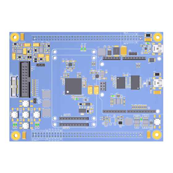
This chapter provides information on the major components and peripherals on the board along with instructions for installing and setting up the evaluation software. Product Overview The board features: • Analog Devices ADSP-CM419F processor 212 ball BGA • 16MHz and 30 MHz oscillators • Analog Devices Unity-Gain Stable, Ultralow Distortion, 1 nV/√Hz Voltage Noise, High Speed Op Amp (AD8639) -
Page 11: Default Configuration
Default Configuration The CPA Development Board is designed to run as a standalone unit or can be used as a plug in card to other power Default Hardware Setup boards. The figure shows the default settings for jumpers and switches and the location of the jumpers, switches, connectors, and LEDs. -
Page 12: Block Diagram
Block Diagram Figure 2: CPA Block Diagram... -
Page 13: Analog Input Channel Selection
Analog Input Channel Selection The ADSP-CM419F has 24 x 16 bit ADC Input Channels and 7 x 14 bit ADC Input Channels as follows: ® • 16 bit ADC channels connected to Cortex M4 • A0 - A7 • B0 - B7 •... -
Page 14: Power Architecture
Power Architecture Digital Supply The ADSP-CM419F has two primary voltage domains: 3.3V and 5.0V. The 5.0V source can be selected to input from the USB connector (J200) or from the connector interface (X401). The Analog Devices ADM7170ACPZ provides 3.3V to the analog circuitry while the ADP2119 provides 3.3V to the digital circuitry. -
Page 15: Bit Serial Flash Memory With Dual And Quad Spi (W25Q64)
64M-bit Serial Flash Memory with Dual and Quad SPI (W25Q64) The W25Q64FV (32 Mb) Serial Flash memory provides a storage solution for systems with limited space, pins and power. The 25Q series offers flexibility and performance well beyond ordinary Serial Flash devices. They are ideal for code shadowing to RAM, executing code directly from Dual/Quad SPI (XIP) and storing voice, text and data. -
Page 16: Dual Channel Digital Isolator - 5K Rms (Adum2281)
Dual channel Digital Isolator – 5K RMS (ADuM2281) The ADuM2280/ADuM2281/ADuM2285/ADuM2286ADuM228x in this data sheet) are 5 kV rms dual-channel digital isolators based on Analog Devices, Inc., iCoupler® technology. Combining high speed CMOS and monolithic air core transformer technology, these isolation components provide outstanding performance characteristics superior to alternatives, such as optocoupler devices and other integrated couplers. -
Page 17: Kv Digital Isolator With 5V Dc-To-Dc (Adum6201)
The ADuM6200/ADuM6201/ADuM62021 are dual-channel digital isolators with isoPower®, an integrated, isolated dc-to-dc converter. Based on the Analog Devices, Inc., iCoupler® technology, the dc-to-dc converter provides up to 400 mW of regulated, isolated power at either 5.0 V or 3.3 V from a 5.0 V input supply, or at 3.3 V from a 3.3 V supply at the power levels shown in Table 1. -
Page 18: Tft Lcd
TFT LCD This 2.2-inch TFT LCD module features a SPI interface fully compatible with popular LCD5110 interface. Features • TFT01_2.2 SP is a 2.2 "SPI TFT LCD Screen Module, 10pins interface, compatible LCD5110 interface. Not just a LCD but also includes an SD card connector. •... -
Page 19: Hardware Reference
Figure 3-1: Block Diagram This CPA board is designed to demonstrate the ADSP-CM419F processor’s capabilities. The board has a 30 MHz input clock and runs at 240 MHz internally. User I/O to the processor is provided in the form of five pushbuttons... -
Page 20: Reset Pushbutton ( Res )
Reset Pushbutton ( The reset pushbutton resets the ADSP-CM419F processor. The reset signal also is connected to the expansion connectors via the signal. Reset ( is used to indicate when the board is in reset. SYS_HWRST D705... -
Page 21: Gpio Pushbuttons (Sw A To E)
GPIO Pushbuttons ( SW A to E The GPIO pushbuttons are connected to the processor’s signals PF_08, PA_00, PA_01 PE_14 PE_15 respectively. These pushbuttons are enabled through S706 dip switch which can enable or disable each connection to the processor Figure 7: Push button circuit connections to ADSP-CM419 Table 3-1: Pushbutton Enable Switch –... -
Page 22: Led Enable ( S705 )
LED Enable ( S705 The LED enable switch is used to connect/disconnect the LEDs from the processor. When the switch is in the ON position the respective signal is connected between the LED and the processor. When the switch is in the OFF position the respective signal is disconnected between the LED and the processor and the signal can be used for another function. -
Page 23: Vdd_Int Regulator
VDD_INT Regulator The VDD_INT regulator is an internal voltage regulator supplying the VDD_INT power to the processor. This supplies 1.2V to the internal Flash of the processor. It is controlled from an internal base drive circuit, regulating the supply.There is therefore no need for an external supply. See circuit below for details. Figure 9: Internal Regulator... -
Page 24: Vref Source (Jp500)
VREF Source (JP500) The VREF source jumpers select whether an internal or external voltage reference supplies the VREF0, VREF1 and VREF2 signal of the processor. This jumper must be installed. This selection also determines the DC Bias of the input of the ADC. This is midscale of the ADC range (3.0V). ADC VINx At the input of each ADC channel there is an RC circuit positioned almost directly at the input pin of each ADC channel. -
Page 25: Main Power Select ( Jp200 )
Main Power Select ( JP200 The main power select jumper selects whether the main power source for the board is provided from the USB or an the optional 5V external source through the connector X401. The default setting is USB. Table 3-12: Main Power Select Jumper Position... -
Page 26: Clock
Clock The clock connectors allow for a connection point to the SYS_CLKIN0 and SYS_CLKIN1 input pins of the processor. Two other clocks are generated - FPGA_CLK0 and FPGA_CLK1 which are used to drive any CPLD or FPGA devices that may be connected to the external connector. The clocks are fixed at 30MHz and 16MHz respectively. -
Page 27: Lcd
Part Description Manufacturer Part Number 2.2" TFT LCD Adafruit 1480 Character Display (J21) Part Description Manufacturer Part Number 20x2 character display Newhaven Display NHD-0220D3Z-FL-GBW-V3 Debug (X602) The debug connectors provides a connection point for the emulator to interface with the processor. There are two debug connectors on the board.
Need help?
Do you have a question about the ADSP-CM419F and is the answer not in the manual?
Questions and answers