
Related Manuals for Aastra NeXspan C


Summary of Contents for Aastra NeXspan C
- Page 1 Integrated DECT Service Installation guide NeXspan C/S/L/D - NeXspan 50 - NeXspan 500 AMT/PTD/PBX/0020/2/4/EN 01/2007 © AASTRA MATRA Telecom...
- Page 2 Page 2 01/2007 AMT/PTD/PBX/0020/2/4/EN...
-
Page 3: Table Of Contents
NeXspan C/S/L/D ........ - Page 4 Chapter 4 - Implementation of hardware on NeXspan C/S/L/D ....67 Conventions used for card names ......67 Interface cards .
- Page 5 Base station synchronization ....... . .93 Chapter 5 - Implementation of hardware on NeXspan 50 ....95 Interface card .
- Page 6 6.2.8 DECT CLOCK INTERFACES ........124 6.2.9 Connecting the LDT board .
- Page 7 Chapter 9 - Programming for the NeXspan C/S/L/D range ....163 Introduction ..........163 Manage topology .
- Page 8 10.12 Declare and register a mobile .......186 10.13 Declare the DECT subscribers ......186 Chapter 11 - Multi-site programming .
-
Page 9: Chapter 1 - Introduction
Chapter 4: Implementation of hardware on NeXspan C/S/L/D This chapter describes the interface cards to be used in an NeXspan C/S/L and the wiring layout between the system and the DECT base stations. -
Page 10: Audience
Chapter 8: Checking the installation This chapter describes the preliminary operations common to both the NeXspan C/S/L/D, NeXspan 50 and NeXspan 500 ranges before the DECT installation is programmed and put in service. Chapter 9: Programming for the NeXspan C/S/L/D range This chapter describes the programming steps to put in service the integrated DECT service for NeXspan C/S/L./D... -
Page 11: Reference Documents
[14] Operating manual NeXspan 50 - Volume 4 (AMT/PTD/PBX/0011*) [15] Operating manual NeXspan 50 - Volume 5 (AMT/PTD/PBX/0012*) [16] Installation and Maintenance Manual - NeXspan C/S/L/D Range (AMT/PTD/PBX/0058*) [17] M910/M915 User’s guide (AMT/PUD/PTD/0001*) [18] M920 M921 M922 User Guide (PS10419*) -
Page 12: Abbreviations
M6540 IP PBX range PBX range including MC6530, MC6530E, MC6550, and M6550 IP PBX, NeXspan 50 and NeXspan 500 PBX range comprising NeXspan D (XD), NeXspan L (XL), NeXspan S (XS) and NeXspan C (XC) Fixed Part Subnumber Generic Access Profile IPEI... -
Page 13: Definitions
Definitions 1.5.1 Definitions concerning deployment • Coverage area The coverage area refers to the space within which the user of a mobile must be able to transmit and receive calls. This area can include coverage both inside and outside a building. •... - Page 14 • case 2: ¨B1, B2, and B3 are base stations, each with its own radio area. Each time a cordless handset is located at the intersection of these three areas, it recognises the three base stations with the same radio level. •...
- Page 15 • Radio area: The radio area is the basic element in radio coverage. The radio area is the zone in which a base station transmits and receives signals. However, depending on the traffic conditions (number of simultaneous calls required within the same office), it may be necessary to install multiple base stations adjacent to one another covering virtually the same radio area.
-
Page 16: Overlapping Radio Areas
• Roaming: mechanism for changing the channel for a cordless handset during communication or when no call is set up (roaming). • Handover: mechanism for changing the base station during communication. radio area 8-base station cell : DECT base station centre of radio area (3 overlapping base stations maximum) Figure1: Example deployment... - Page 17 Examples of representation of these measurements: The graphs below show the change in the RSSI level according to the distance from the base station studied. The graphs are linked to the chosen direction. To determine whether the overlap of the two radio areas is correct, you must have the two measurements in both directions for the plan concerned (for example on horizontal axle of base station 1, right direction –...
-
Page 18: Pari/Sari Management (Mobile Access Rights)
ARC, Access Right Class. Radio communication standard used by the PBX (e.g. B class multi-cellular PBX). • EIC, Equipment Installation Code: distributor reference (example: AASTRA) managed by the ETSI. • FPN + FPS, Fixed Part Number and Fixed Part Sub-number. Network user reference (AASTRA customer) or PBX reference (see below), managed by AASTRA. -
Page 19: Constructing The Authentication Key
FOR A SINGLE-SITE PBX MANAGING LESS THAN 32 CELLS: A single PARI assigned to all the base stations is provided by AASTRA. Authorization access is performed by testing the PARK registered in the mobiles which must correspond to the PARI. - Page 20 Page 20 01/2007 AMT/PTD/PBX/0020/2/4/EN...
-
Page 21: Chapter 2 - Description
Chapter 2 - Description Description The integrated DECT is designed to operate with NeXspan C/S/L/D, NeXspan 50 and NeXspan The DECT system contains the following components: • the mobile set which enables the user to use PBX telephony features •... -
Page 22: Dect Radio Base Stations
DECT radio base stations 2.2.1 Physical description A DECT base station consists of a plastic housing and an electronic card. The electronic card manages the ISDN interface. One radio module mounted on the card manages the radio interface. A DECT base station is equipped as standard with two quarter-wave antennas integrated into the unit. - Page 23 Figure 2-2: Presentation of a DECT base station If the base station is mounted on a "metal structure" partition, the base station must be 60 to 80 cm from the partition using an extension bracket. Connections The maximum cable distance permitted between a base station and the PBX is 800 meters (principle of the point-to-point S0 bus).
- Page 24 In cases where old wire is to be reused, it is recommended to carry out 4 tests: cross-talk measurements at 100 kHz (decoupling check and detection of any cross-talk) near-end cross-talk measurements (> or = 60dB) degeneration measurements at 10khz (alpha < 6 dB) loop resistance measurements (R loop = R termination + R cable) To facilitate connection to the base station, it is recommended to use: •...
- Page 25 • J202: power supply jack used to supply power locally to the base station. J201 S202 J202 The black square represents the position of the switch. Figure 2-3: Overview of the electronic card on the old M6241 base station New M6241 base station connections The base station is connected to its environment using 5 connectors: •...
- Page 26 • J5: power supply jack used to supply power locally to the base station. The black square represents the position of the switch. Figure 2-4: Overview of the electronic card on the new M6241 base station The cable used to connect a base station to an S0 wall jack must conform to the France Telecom CSE B31-21 standard: •...
- Page 27 MAT Equipement HT6116A Connection kit for external antenna AASTRA Table 3: References of antennas used by DECT base stations A 50-centimeter cable equipped with a male TNC connector is provided with the bidirectional antenna (MA821X12). To retain the gain/directivity character of this antenna, do not add cables between the antenna and the base station.
- Page 28 The internal antenna comprises an MMS connector (1), a KX21 coaxial cable (2) and a radiating element (3). The external antenna is connected using a cable (4-5-6) comprised of a male MMS connector (4), a KX21 coaxial cable (5) and a female TNC connector (6). Radiall gives losses of less than one dB (guaranteed).
-
Page 29: Functional Description
2.2.2 Functional description The DECT base station transmits and receives radio signals to and from the mobile. 4-channel base station The D channel of the S0 BRI transports the signal between the PBX and the base station. The 2 B channels are used to transport the ADPCM encoded 4-channel voice signals at 32 Kb/S. DECT base stations are connected to the PBX using standard S0 interface cards with a 144 kb/s throughput and a 2-pair cable (S0 point to point pinout). -
Page 30: Specifications
2.2.3 Specifications The characteristics of the DECT base station are as follows: • Frequency band: 1880 -1900 MHz. • Number of radio channels: 10. • Transmission power: 250 mw maximum / 10 mw average. • Instantaneous throughput of the channel: 1152 kbit/s •... -
Page 31: Configuration Of The Old M6241 Dect Base Station
2.2.4 Configuration of the old M6241 DECT base station • Configuration of the switches on the base station’s electronic card (see figure 3 page 25): Switches CA1 Status Description CA1-1 on ON Activation of the adaptation resistor on the synchronization pair (factory configuration) CA1-2 on ON The base station reset is only activated when the base station or... -
Page 32: Configuration Of The New M6241 Dect Base Station
2.2.5 Configuration of the new M6241 DECT base station • Configuration of the switches on the base station’s electronic card (see figure 4 page 26): Switches CA1 Status Description CA1-1 on ON Activation of the adaptation resistor on the synchronization pair (factory configuration) CA1-2 on ON The base station reset is only activated when the base station or... -
Page 33: M90X Mobile Terminals
M90x mobile terminals 2.3.1 Physical description of an M90x mobile Description The M90x mobile terminal comprises: • the mobile set with its battery • a charger • a power supply cable and mains power unit • a belt clip kit Figure 2-6: View of an M90x mobile terminal For more detailed information, refer to document [3] (see "Reference documents"... -
Page 34: Configuring An M90X Mobile Terminal
2.3.2 Configuring an M90x mobile terminal Registering an M90x mobile terminal A. Check that the mobile has not already been registered. The cordless handset must not contain any "parasite" registrations (for example, from previous use on another DECT system). In the standard case where the mobile is to be used on one DECT system only, it must not be registered on any other base at the outset. - Page 35 "Enter code" appears on the display Enter the "set number + PBX registration code" and press OK The set displays "Please Wait". • "Still waiting" • "Declare base OK" or "Failed, Retry" Stop and restart the mobile, then check to see if it is active. Deregistering an M90x mobile terminal Press the Menu key...
- Page 36 M90x mobile DEBUG mode The debug menu is used to view the radio quality of the base stations detected by the mobile terminal. This mode consists of two screens: the first screen gives information about the current base station, whereas the second screen provides information on other base stations detected by the mobile terminal.
- Page 37 Definition of the debug screen corresponding to the current base station B S I Figure 2-7: Debug screen for the current base station of an M90x mobile terminal • XX: RPN Indicates the number of base station used by the mobile •...
- Page 38 Definition of the debug screen corresponding to other base stations detected by the mobile terminal Figure 2-8: Debug screen for other base stations detected by the M90x mobile terminal • C3C3/R3R3: RPN and RSSI Indicates the third best available base station for handover in cell XX •...
-
Page 39: M910/M915 Mobile Terminals
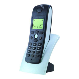
M910/M915 mobile terminals 2.4.1 Physical description of an M910/M915 mobile terminal Description The M910/M915 mobile terminal comprises: • a terminal • a charging unit • an adapter • 3 AAA-NiMH batteries • 2 User Guides (in French and English) Figure 2-9: View of an M910 mobile terminal For more detailed information on the use of an M910/M915 mobile terminal, refer to document [15] (see "Reference documents"... - Page 40 M910 Specifications • Weight: 135 grams. • Dimensions: 136 x 48 x 23 mm. • Autonomy: 15 hours talktime, 180 hours in standby mode. • Registration of terminal with a maximum of four 4 DECT/GAP base stations • Display unit (LCD): 2 lines x 12 characters + 1 line for icons. •...
- Page 41 Headset for M915 - Specifications • Plug diameter: 2.5mm • 32 ohms mini. • headset reference: TC2070A Figure 2-10: View of an M915 mobile terminal AMT/PTD/PBX/0020/2/4/EN 01/2007 Page 41...
-
Page 42: Configuring An M910/M915 Mobile Terminal
2.4.2 Configuring an M910/M915 mobile terminal Registering an M910/M915 mobile terminal It is important to follow the procedure below when registering the M910 for the first time. On the mobile terminal, the line "Register" is displayed. Press the Menu key, select System using the keys and confirm with OK . - Page 43 Keypad lock function The keypad lock function is accessible via the “Security” menu. Use this menu with caution. If the user forgets his PIN code, the only way the code can be reactivated is by resetting the mobile with a special tool. The mobile needs to be sent to the manufacturer repair centre for this to be done.
-
Page 44: M92X Mobile Terminals
M92x mobile terminals 2.5.1 Physical description of an M92x mobile Description Although M92x and M90x mobile terminals are physically identical, M92x mobile terminals offer the following hardware and software upgrades: • Replacement of obsolete components • Introduction of new functions: •... - Page 45 Specifications • Weight: 120 grams. • Dimensions: 135 x 58 x 19 mm. • Autonomy: 10 hours talktime, 72 hours in standby mode. • GAP compatibility (CTR22 standard). • Charger: wall or mobile unit. • Full graphic display: 3 lines x 12 characters with 14 icons. •...
- Page 46 New features in M92x Note: For more detailed information on the use of an M92x mobile terminal, refer to document [15] (see "Reference documents" on page 11). The new features available in the M92x mobile terminal are: • new graphical display (new pictograms and new fonts) •...
-
Page 47: Configuring An M92X Mobile Terminal
2.5.2 Configuring an M92x mobile terminal Registering an M92x mobile terminal A. Check that the mobile has not already been registered. The cordless handset must not contain any "parasite" registrations (for example, from previous use on another DECT system). In the standard case where the mobile is to be used on one DECT system only, it must not be registered on any other base at the outset. - Page 48 Deregistering an M92x mobile terminal Press the Menu key Enter the installer code 9995. Press the middle key several times until "Declare" is displayed Press the Declare key The display shows: Declare base number? 1 2 3 4 Press the key to select the base to be deleted and confirm by pressing the OK The set displays: Delete base n...
- Page 49 M92x mobile DEBUG mode The debug menu is used to view the radio quality of the base stations detected by the mobile terminal. This mode consists of two screens: the first screen gives information about the current base station, whereas the second screen provides information on other base stations detected by the mobile terminal.
- Page 50 • XX: RPN (radio part number) Indicates the number of base station used by the mobile • F: Frequency Indicates the frequency used by the mobile (0 …. 9) • S: Slot number Indicates the slot number used by the mobile ( 0…….b) •...
- Page 51 The following information is used for laboratory development: • Sx: indicates periodic scanning of DECT channels • HI x: indicates, during a call, whether the external handover is valid (indicator of external HO received from base station). Definition of the debug screen corresponding to other base stations detected by the mobile terminal A44:0 A44:0...
- Page 52 Indication on the backup base station table that the base station has disappeared The backup base station table is sorted in descending RSSI order. If a base station is not detected after 3 full scanning operations on all the channels, its RSSI in the table is divided by two.
-
Page 53: Functional Description Of M90X, M910 And M92X Mobile Terminals
Functional description of M90x, M910 and M92x mobile terminals An NeXspan C/S/L/D or NeXspan 50 or NeXspan 500 PBX manages terminal mobility with the following functions: Authentication Mobile authorization procedure. The decision to initiate the procedure is controlled by the PBX. - Page 54 If an attempt is made to call a non-located set: • the call is forwarded to the backup set, if declared (recommended solution), then to the voice mailbox, if declared. • If no backup set is declared, external calls are lost and internal calls receive the busy tone after 20 seconds searching for the mobile.
-
Page 55: Capacity
48 V supplied by 2 base stations ADS50X 4 channels (if UCT2-C equipped with an ADPCM16 daughter card) Table 9: Radio network capacities of NeXspan C/S/L/D PBXs The maximum number of DECT mobile terminals is 256. AMT/PTD/PBX/0020/2/4/EN 01/2007 Page 55... -
Page 56: Nexspan 50 / Nexspan 500
2.7.2 NeXspan 50 / NeXspan 500 S0 interface cards Power Capacity For 1 CCUs LDS + ADPCM32 or 48 V supplied by 64 base stations LDT + ADPCM32B ADS850 4 channels For 37 CCUs LDS + ADPCM32 or 48 V supplied by 256 base stations LDT + ADPCM32B ADS850... -
Page 57: Chapter 3 - Deployment Principles
Chapitre 3 - Deployment principles Description Before beginning deployment procedures ensure that the following studies have been conducted: • Radio coverage for the entire site. It must be possible to send and receive calls within the coverage area. • Site traffic study. The number of simultaneous calls must be determined according to the number of users and their habits. -
Page 58: Determining The Radio Coverage
Determining the radio coverage This section describes the principles of the site survey for positioning base stations in order to achieve complete coverage of the area. The purpose of deployment is to determine where to locate the base stations. This cannot be achieved using only building plans;... - Page 59 Metal structures found in conference halls and production rooms can also cause radio waves to be reflected due to their large metal structures. The resulting interference reduces the base station’s range. Once the nature of the materials has been identified in the coverage areas, the size of the radio areas can be evaluated, taking the following information into account: Average range Type of premises...
- Page 60 Measure the horizontal range on the floor below. Without moving the radio base station, go to the floor directly below and measure the horizontal coverage again. Note: If the building allows good radio signal penetration, the vertical coverage could extend to one floor above or below the one where the base station is located.
-
Page 61: Method Of Determining The Number Of Base Stations According
Method of determining the number of base stations according to predicted traffic This method allows you to determine the number of base stations required to provide service in a coverage area. Proceed as follows: Identify the traffic areas and divide them into two categories: •... - Page 62 Dimensioning for a 4-channel base station: Number of radio base stations for a given area according to traffic mobility parameters, and the ratio of the number of mobiles to the number of radio areas in the coverage area. MEDIUM HIGH (0.2) (0.5) (0.8)
- Page 63 Example: 20 mobiles 10 mobiles 60 mobiles DECT base station cell 2 radio area cell 3 cell 4 cell 0 cell 1 Homogenous area 1 Homogeneous Homogenous area 3 "Low" traffic area 2 Very "high" traffic "Medium" traffic Figure 3-1 : Example of deployment The deployment study produced the following information: •...
-
Page 64: Grouping Radio Areas Into Cells
Grouping radio areas into cells Since the cell is the mechanism by which the PBX locates the mobiles, it is necessary to group the radio areas into cells. The following criteria used to group radio areas into the same cell do not taken into account whether the area is homogenous or special, but consider only geographic proximity: •... -
Page 65: Installing And Connecting The Base Stations
If possible, check the link with a scanner. • On the NeXspan C/S/L/D range, connection is set up using a category 5 wire or a wire with twisted pairs (for connection with RJ45 connectors). A twisted cable (a 3/6 pair and a 4/5 pair) is required to connect DECT base stations to the integrated S0 accesses of the CPU card. - Page 66 Page 66 01/2007 AMT/PTD/PBX/0020/2/4/EN...
-
Page 67: Chapter 4 - Implementation Of Hardware On Nexspan C/S/L/D
UCT-S, UCTS-12 et UCT-C. Interface cards The cards used to connect DECT base stations to NeXspan C/S/L/D range devices are: • LD4/LD4NX cards, If necessary equipped with the ADPCM16 daughter card. - Page 68 800ms clock transmitted by the master base station via the third pair. UCT-S, UCTS-12 and UCT-C cards The UCT-S, UCTS-12 and UCT-C cards are NeXspan S, NeXspan S12 and NeXspan C CPU cards with four T0/S0 interfaces. The T0/S0 interfaces are used to connect: •...
-
Page 69: Factory) Configuration Of The Ld4 St Card With Stocko Format
(Factory) configuration of the LD4 ST card with Stocko format The black square represents the position of the switch. Figure 4-1: Top view of the LD4 ST card AMT/PTD/PBX/0020/2/4/EN 01/2007 Page 69... - Page 70 Figure 4-2: Bottom view of the LD4 ST card Page 70 01/2007 AMT/PTD/PBX/0020/2/4/EN...
-
Page 71: Description Of The Connectors
4.3.1 Description of the connectors Label Feature 40 V remote power supply connection Factory reserved. Factory reserved J5 and J6 ADPCM 16 daughter card connection Connection for 2 DECT base stations Interface 2: Interface 3: Pin 5: ED2 Pin 1: ED3 Pin 6: NED2 Pin 2: NED3 Pin 7: RD2... -
Page 72: Description Of The Switches
4.3.2 Description of the switches CA1.1 to CA1.4: these switches are used to adapt lines (factory setting, leave set to ON). CA2 (located on the copper side): configure according to the card's location and mode (master/ slave). For LD4 ST in T0 CA2.1 Feature (VALH) -
Page 73: Position Of Ld4 St Card
Table 4: Description of switches SW7 and SW8 on the LD4 ST card 4.3.3 Position of LD4 ST card The possible slots and restrictions for the LD4 card in a NeXspan cabinet are the same as for the LD4NX card see § 4.6.5. 4.3.4 Connecting base stations Each terminal is connected to the ISDN S0 (BRI) of an LD4 ST card, and uses two pairs: 1 transmit pair and 1 receive pair. -
Page 74: Factory) Configuration Of The Ld4 Rj Card With Rj45 Format
(Factory) configuration of the LD4 RJ card with RJ45 format Figure 4-4: Overview of the LD4 RJ card 4.4.1 Description of RJ45 connectors • 8 x 8-pin RJ 45 ports CONSOLE LD4 X Figure 4-5: Front panel of LD4 RJ card Check that signals match pins: LINE NO. -
Page 75: Switch Settings
Note: 40 V can also be supplied on connector T3 (connect the 40 V supply unit to connector T3, and the base station to connector S3). 4.4.2 Switch settings CA1.1 to CA1.4 (ADAPT): these switches are used for line adaptation. Leave these switches on the setting ON (factory setting). -
Page 76: Position Of Ld4 Rj Card
SW7 and SW8: the jumpers allow the selection of a 40 V or 48 V power supply. Note: The power supply units of the NeXspan range do not supply ISDN 40 V. To supply 40 V to sets and/or base stations, connect an external power supply unit to the T3 connector on the LD4 RJ card. - Page 77 RJ45 DECT base station Figure 4-6: Connecting a base station to an S0 interface of an LD4 RJ card S0 interface link with DECT base station: LD4 RJ card RJ45 connector Base station RJ45 connector Pin 6 (NRD1) Pin 6 Pin 3 (RD1) Pin 3 Pin 5 (NED1)
-
Page 78: Factory) Configuration Of The Ld4Nx St Card With Stocko Format
(Factory) configuration of the LD4NX ST card with Stocko format 1 2 3 J1-1 J2-1 J1-2 J2-2 DISA CA1 HVAL J1-3 J2-3 J1-4 J2-4 5 10 CA1 HVAL CA1.1 = ON HVAL CA1.1 = OFF H not validated CA1.2 = not wired Figure 4-7: Top view of the LD4NX ST card There are two operating modes on the LD4NX ST card: •... -
Page 79: Description Of The Connectors
4.5.1 Description of the connectors LABEL FUNCTIONS/CHARACTERISTICS CONTACTS 96-pin connector: backplane connection. STOCKO male connector, 2 pins: receives the ISDN 40 V remote power supply when the latter is • Pin 1: M40V not available on the PBX backplane (40 V only •... -
Page 80: Switch Settings
4.5.2 Switch settings Note: The Master/Slave micro-switch of previous LD4 cards no longer exists. The LD4NX ST card is always in DECT slave mode; it cannot generate the DECT clock. The LD4NX ST card has no micro-switch for downloading the flash memory with a BOF3 type tool (automatic detection). -
Page 81: Description Of The Diodes
4.5.3 Description of the diodes Label Color Feature Green Shows the operating status of the card DISABLED Orange Not used Table 13: Description of LD4NX ST card LEDs 4.5.4 Position of LD4NX ST card The possible slots and restrictions for the LD4NX card in LD4N mode in a NeXspan cabinet are the same for the LD4 card, see §... -
Page 82: Factory) Configuration Of The Ld4Nx Rj Card With Rj45 Format
(Factory) configuration of the LD4NX RJ card with RJ45 format 1 2 3 J1-1 J2-1 J1-2 J2-2 CA1 HVAL J1-3 J2-3 J1-4 J2-4 CA1 HVAL CA1.1 = ON HVAL CA1.1 = OFF H not validated CA1.2 = not wired LD4NX Console Figure 4-9: Overview of the LD4NX RJ card There are two operating modes on the LD4NX RJ card:... -
Page 83: Description Of The Connectors
4.6.1 Description of the connectors LABEL FUNCTIONS/CHARACTERISTICS CONTACTS 96-pin connector: backplane connection. HE14 connector - 1 x 8 male pins: used for not used loading programmable components "On Site" (reserved for manufacturer). J5 and J6 Two connectors AMP CMS 2 x 10 female pins: hosts an ADPCM16V daughter card. -
Page 84: Switch Settings
4.6.2 Switch settings Note: The Master/Slave micro-switch of previous LD4 cards no longer exists. The LD4NX RJ card is always in DECT slave mode; it cannot generate the DECT clock. The LD4NX RJ card has no micro-switch for downloading the flash memory with a BOF3 type tool (automatic detection). -
Page 85: Description Of The Diodes
4.6.3 Description of the diodes LABEL STATUS EXPLANATION RUN (green) Flashing rapidly Card in service OFF (orange) Card can be removed while powered up Table 18: Description of LD4NX RJ card LEDs Note: You are advised to disable the card before removing it. 4.6.4 Description of push buttons LABEL EXPLANATION... - Page 86 An LD4/LD4NX card (in LD4N mode) with ADPCM16 daughter card can be fitted in slots 6 and 7 without restriction. It is not allowed in slots 08 to 13. When an LD4/LD4NX + ADPCM16 card is fitted in slot 00, no card on the short list may be fitted in slot 08;...
-
Page 87: Connecting Base Stations
4.6.6 Connecting base stations Each base station is connected to the ISDN S0 (BRI) interface of an LD4NX RJ card, and uses two pairs: 1 transmit pair and 1 receive pair. Note: If there are a DECT base station and an S0 terminal (other than the base station) on the same card, the base station must be powered with a 40 V supply. -
Page 88: Configuring S/T Accesses Of Uct-S, Ucts-12 And Uct-C Cards
Configuring S/T accesses of UCT-S, UCTS-12 and UCT-C cards 4.7.1 S/T access of a UCT-S card S.DECT P.DECT PARALLEL PORT MUSIC S/T-3 S/T-2 S/T-1 S/T-0 PRINTER CONSOLE ALARM / REMOTE CONTROL 10/100-TX Figure 4-14: Front panel of a UCT-S card The UCT-S card has four T0/S0 interfaces (4 RJ45 connectors) for connecting four 2-channel DECT base stations (on UCT1-S first generation card) and 4-channel (on UCT2-S seconde generation or UCT3-S third generation card equipped with an ADPCM16 daughter card). -
Page 89: Description Of S/T Connectors Of Uct-S, Ucts-12 And Uct-C Cards
4.7.4 Description of S/T connectors of UCT-S, UCTS-12 and UCT-C cards Pin no. S/T3 S/T2 S/T1 S/T0 NRD3 NRD2 NRD1 NRD0 NED3 NED2 NED1 NED0 Table 21: Pinout of S/T connectors on UCT-S, UCTS-12 and UCT-C cards Note: The default pinout is set to connect T0 accesses directly (straight cable). A twisted cable or T0/ S0 adaptor is required to connect DECT base stations. - Page 90 J30xx S/T3 J29xx No remote power supply S/T2 48 V Power supply S/T1 40 V Power supply (option) S/T0 No remote power supply UCT FRONT PANEL Figure 4-17: Configuring remote power supply of S/T0 to S/T3 accesses Page 90 01/2007 AMT/PTD/PBX/0020/2/4/EN...
-
Page 91: Connecting Base Stations
The state of the jumpers can be viewed via MMC: Menu 3.2.4 ISDN BOARD SWITCHES STATUS SLOT TYPE DIREC/TG SYNC REMO-SUPL -------------------------------------------- 0-02-00 0-02-01 DECT BASE TG0 0-02-02 FT0-ETSI 0-02-03 FT0-ETSI 1-01-00 1-01-01 1-01-02 1-01-03 Figure 4-18: Status of ISDN card jumpers (Menu 3.2.4) Note: The jumper status of LD4NX cards in LD4X mode equipped in the PBX are also displayed (in this example, the card is equipped in slot 1-01). - Page 92 A twisted cable or S0/T0 adaptor is required to connect DECT base stations. 2 3 4 5 6 7 2 3 4 5 6 7 UCT-S/T-C Standard point-point cable 2 3 4 5 6 7 Crossover Twisted cable 2 3 4 5 6 7 Standard point-point cable DECT base...
-
Page 93: Base Station Synchronization
Base station synchronization DECT base stations connected to S0 accesses of an LD4/LD4NX card and to the S0 integrated accesses of seconde generation UCT2-S/UCT2S-12/UCT2-C or third generation UCT3-S/ UCT3S-12 cards are synchronized by the software, by the M bit of the S frame. DECT base stations connected to integrated S0 accesses of a first generation UCT1-S/UCT1S- 12/UCT1-C card are synchronized by a third pair. - Page 94 UCT1-S cards), a third pair may need to be wired for synchronization (pins 1 and 2 of the base station RJ45 connector); see the Chapter "Multi-site synchronization". Note: Multi-site DECT synchronization via third pair is not possible with NeXspan C and NeXspan S12.
-
Page 95: Implementation Of Hardware On Nexspan 50
Chapter 5 - Implementation of hardware on NeXspan 50 Interface card LDS/LDT cards, possibly fitted with one or two ADPCM32 (LDS) and ADPCM32B (LDT) daughter cards are used to connect DECT base stations to a NeXspan 50. LDS/LDT cards have T0/S0 interfaces for managing 2- or 4-channel DECT base stations. There are two versions of each card: •... -
Page 96: Front Panel
5.2.2 Front panel REA5 REA6 + 5 V S0 to S15 Interface Activation Display (level 1) Address not recognised (Fault) REA5 Rapid LED flashing --> Card operational Slow LED flashing --> Card not operational REA6 Not significant (LED off) LED steady on--> Card operational LED off -->... -
Page 97: Equipment On Top Side
5.2.3 Equipment on top side power supply power supply 1 2 3 ADPCM32 ADPCM32 (2,3) (6,7) (10,11) (14,15) (0,1) (4,5) (8,9) (12,13) The black square represents the position of the switch. J6, J7, J8, J9: ADPCM32 daughter card equipment J10, J11, J12, J13: equipment of second ADPCM32 daughter card Figure 5-2: Top view of the LDS card AMT/PTD/PBX/0020/2/4/EN 01/2007... -
Page 98: Equipment On Bottom Side
5.2.4 Equipment on bottom side The black square represents the position of the switch. Figure 5-3: Bottom view of the LDS card Page 98 01/2007 AMT/PTD/PBX/0020/2/4/EN... -
Page 99: Switch Settings
5.2.5 Switch settings Flash Eprom programming switches • CA1.2 = ON -> Flash Eprom programming (card not operational) • CA1.2 = OFF -> Card operational Mandatory Position 100 Ohm adaptation straps • CA1_i.1 = ON and CA1_i.2 = ON -> Access adapted 100 Ohms •... -
Page 100: Lds Card Layout
5.2.6 LDS card layout The LDS card can be fitted in the shelves in accordance with the configuration file. The card is connected to the synchronous bus via the AVADQ or AVLDT terminator inserted in a CFX front slot (corresponding to CLX slot on the LDS card). For more detailed information, refer to document [12] in the reference documents. -
Page 101: Connecting The Lds Card
5.2.7 Connecting the LDS card The LDS card is connected to the distribution frame by a special cable, also used for the remote power supply connection and the RSU connection if a T0 interface is synchronising on the LDS card. If there is no synchronising T0 on the LDS card, cable HG4301A or B is used. - Page 102 PLDS card A PLDS card is required for each LDS card to be supplied with remote power. Fuses are positioned on the PLDS card to select either 40 V or 48 V voltage (48 V as standard unless an S0 interface supplied with remote power is to be configured on the card). The remote power is supplied to the LDS card interfaces via the part of the cable terminating with the J4 connector.
-
Page 103: Distribution Frame Wiring With Cable Hg4302A
5.2.8 Distribution frame wiring with cable HG4302A On the distribution frame end the cable has: • 4 yellow terminal strips (16 transmission/reception interfaces), • 1 red terminal strip (DECT synchronization ). RJ45 S0 / DECT NED0 NRD0 NED1 NRD1 NED2 NRD2 NED3 NRD3... -
Page 104: Configuring The Ldt Card
Configuring the LDT card 5.3.1 References and equipment Designation Reference LDTA 16 T0/S0 interfaces for 2- or 4-channel DECT base stations HJ4758A LDTB 8 T0/S0 interfaces for 2- or 4-channel DECT base stations HJ4758B ADPCM32B Daughter card for managing 8 x 4-channel DECT base HJ4402B stations AVADQ... -
Page 105: Front Panel
5.3.2 Front panel REA5 REA6 + 5 V S0 to S15 Interface Activation Display (level 1) Address not recognised (Fault) REA5 Rapid LED flashing --> Card operational Slow LED flashing --> Card operational REA6 Not significant (LED off) LED steady on -->... -
Page 106: Equipment On Top Side
5.3.3 Equipment on top side J2 (+ 48 V or + 40 V) 1 2 3 J1 (- 48 V or - 40 V) 1 2 3 1 2 3 1 2 3 1 2 3 1 2 3 1 2 3 1 2 3 1 2 3 1 2 3... -
Page 107: Switch Settings
5.3.4 Switch settings Automatic resynchronization switch CA1.2 = ON -> Automatic resynchronization CA1.2 = OFF -> LDS operation without automatic resynchronization Remote power supply configuration straps • J1 set to 1-2 = Remote power supply ON • J2 set to 1-2 = Remote power supply ON •... -
Page 108: Connecting The Ldt Board
5.3.6 Connecting the LDT board The LDT card is connected to the distribution frame by a special cable, also used for the remote power supply connection and the RSU connection if a T0 interface is synchronising on the LDT card. If there is no synchronising T0 on the LDT card, cable HG4301A or B is used. - Page 109 PLDS card A PLDS board is required for each LDT board to be remote supplied. Fuses are positioned on the PLDS card to select either 40 V or 48 V voltage (48 V as standard unless an S0 interface supplied with remote power is to be configured on the card). The remote power is supplied to the LDT card interfaces via the part of the cable terminating with the J4 connector.
-
Page 110: Distribution Frame Wiring With Cable Hg4302A
5.3.7 Distribution frame wiring with cable HG4302A On the distribution frame end the cable has: • 4 yellow terminal strips (16 transmission/reception interfaces), • 1 red terminal strip (DECT synchronization ). Note: On an FPHBG2/CSI device, the synchronization signal is sent via the loop and transmitted to the LDT cards via the back plane (see Section 5.4). -
Page 111: Distribution Frame Wiring With Cable Hg4302B
5.3.8 Distribution frame wiring with cable HG4302B On the distribution frame end the cable has: • 2 yellow terminal strips (8 transmission/reception interfaces), • 1 red terminal strip (DECT synchronization ). Note: On an FPHBG2/CSI device, the synchronization signal is sent via the loop and transmitted to the LDT cards via the back plane (see Section 5.4). -
Page 112: Synchronization
synchronization The DECT radio base station synchronization method varies with the device used (FPHBG2/CSI or FPHBG/CSH) and the boards installed (LDS and/or LDT). The back plane assembly FPHBG2/ CSI and FPT30B/FPD30B allows the DECT clock to be sent on the loop and simplifies the DECT synchronization wiring in a single-site configuration. - Page 113 • For remote clusters: the transmission time compensation on the loop must be configured in the RMH board(s) of all the clusters that contain LDT boards to which DECT base stations are connected. This configuration is performed using 11 switches (binary value : ON = 0; OFF = 1) •...
-
Page 114: For A Nexspan 50 Equipped With An Fphbg Back Plane As Well As Csh And Lds/Ldt Cards
5.4.2 For a NeXspan 50 equipped with an FPHBG back plane as well as CSH and LDS/LDT cards The LDS/LDT card manages DECT synchronization by sending the 800ms time signal to DECT base stations on the S0 interface (M bit multi-frame mechanism of the S interface). LDS/LDT cards have two operating modes (configured via jumper CA1.1): •... - Page 115 Connecting the clocks Cable HG4302X is used to connect the DECT clock (800ms). This clock exits on 3 different V11 pairs (see LDS, LDT interfaces). All DECT V11 clock connections should be carried out on the 4G terminal strip. • Incoming (slave card)/outgoing (master card) DECT clock: SYNP (polarity +), SYNN (polarity •...
-
Page 116: Ldt/Lds Card Diagnosis Means On Nexspan 50
LDT/LDS card diagnosis means on NeXspan 50 The method used to check that the LDT/LDS card configuration and the DECT synchronization clocks wiring are correct, rests on the contents reading of some accesssibles registers on these cards. The accessible registers are not the same ones for LDT and LDS card. The command vport must be used under "enter command"... - Page 117 REGISTER RNBRESYNC I/O Address= 5032H Register NBRESYNC gives the number of times that LDT card switches to resynchronization mode. Its maximum value (FFH) is preserved once reached as long as this register is not read again. Note : This register is incremented only if LDT card is in automatic resynchonisation mode. The reading of this one gives to zero the meter REGISTER RFEN Register RFEN, accessible in reading only, contains the localization code of the card.
-
Page 118: Content Reading Of Lds Card Registers
5.5.2 Content reading of LDS card registers REGISTER RFEN Register RFEN, accessible in reading only, contains the localization code of the card. Its content is the code cabled in back plane, that is to say the reverse of the CLX number used for the recognition of the bus system orders I/O Address= 503CH bit 7... -
Page 119: Implementation Of Hardware On Nexspan 500
Chapter 6 - Implementation of hardware on NeXspan 500 Interface card LDT cards, possibly fitted with one or two ADPCM32B daughter cards are used to connect DECT base stations to a NeXspan 500. LDT cards have T0/S0 interfaces for managing 2- or 4-channel DECT base stations. There are two versions of each card: •... -
Page 120: Front Panel
6.2.2 Front panel REA5 REA6 + 5 V S0 to S15 Interface Activation Display (level 1) Address not recognised (Fault) REA5 Rapid LED flashing --> Card operational Slow LED flashing --> Card operational REA6 Not significant (LED off) LED steady on -->... -
Page 121: Equipment On Top Side
6.2.3 Equipment on top side J2 (+ 48 V or + 40 V) 1 2 3 J1 (- 48 V or - 40 V) 1 2 3 1 2 3 1 2 3 1 2 3 1 2 3 1 2 3 1 2 3 1 2 3 1 2 3... -
Page 122: Switch Settings
6.2.4 Switch settings Automatic resynchronization switch CA1.2 = ON -> Automatic resynchronization CA1.2 = OFF -> LDS operation without automatic resynchronization Remote power supply configuration straps • J1 set to 1-2 = Remote power supply ON • J2 set to 1-2 = Remote power supply ON •... -
Page 123: Installing The Ldt Card
6.2.5 INSTALLING THE LDT CARD Proceed as follows to install an LDT card: • "Insert the LDT card in a CLX slot with synchronous bus access. • "Connect it to the synchronous bus with a plug. • "Connect it to a synchronizing clock input in the PBX in the case of a synchronizing T0 interface on the LDT card. -
Page 124: Dect Clock Interfaces
6.2.8 DECT CLOCK INTERFACES The CSI card generates a DECT clock and sends this clock to all the PBX clusters. The synchronization signal is sent via the loop and extracted by the RMH cards. The DECT synchronization signal is then sent to the LDT cards via the backplane. The configuration rules are as follows: •... - Page 125 Figure 6-4: AHG0013X cable Note: New LDT cable must be used if DECT clock (800 ms) forwards by the loop: case of a PBX equipped with FPS backplane, a CSI card and FPG backplane AMT/PTD/PBX/0020/2/4/EN 01/2007 Page 125...
- Page 126 Figure 6-5: HG4302X cable Note: This cable allows to transmit DECT clock 800 ms by the distribution frame Page 126 01/2007 AMT/PTD/PBX/0020/2/4/EN...
-
Page 127: Distribution Frame Wiring With Cable Ahg0013A
6.2.10Distribution frame wiring with cable AHG0013A On the distribution frame end the cable has: • 4 yellow terminal strips (16 transmission/reception interfaces), RJ45 S0 / DECT NED0 NRD0 NED1 NRD1 NED2 NRD2 NED3 NRD3 (A02) (A03) (C02) (C03) (B03) (B04) (C04) (A04) (B05) -
Page 128: Distribution Frame Wiring With Cable Hg4302A
6.2.12Distribution frame wiring with cable HG4302A On the distribution frame end the cable has: • 4 yellow terminal strips (16 transmission/reception interfaces), • 1 red terminal strip (DECT synchronization ). Note: This cable allows to transmit DECT clock 800 ms by the distribution frame RJ45 S0 / DECT NED0... -
Page 129: Synchronization
6.2.14synchronization The set of FPS backplane allows the DECT clock to be sent on the loop and simplifies the DECT synchronization wiring in a single-site configuration The CSI board generates a DECT clock and sends this clock to all the PBX clusters. The synchronization signal is sent via the loop and extracted by the RMH boards. - Page 130 • For remote clusters: the transmission time compensation on the loop must be configured in the RMH board(s) of all the clusters that contain LDT boards to which DECT base stations are connected. This configuration is performed using 11 switches (binary value : ON = 0; OFF = 1) •...
-
Page 131: Ldt/Lds Card Diagnosis Means On Nexspan 500
LDT/LDS card diagnosis means on NeXspan 500 The method used to check that the LDT/LDS card configuration and the DECT synchronization clocks wiring are correct, rests on the contents reading of some accesssibles registers on these cards. The accessible registers are not the same ones for LDT and LDS card. The command vport must be used under "enter command"... - Page 132 REGISTER RNBRESYNC I/O Address= 5032H Register NBRESYNC gives the number of times that LDT card switches to resynchronization mode. Its maximum value (FFH) is preserved once reached as long as this register is not read again. Note: This register is incremented only if LDT card is in automatic resynchonisation mode. The reading of this one gives to zero the meter REGISTER RFEN Register RFEN, accessible in reading only, contains the localization code of the card.
-
Page 133: Content Reading Of Lds Card Registers
6.3.16Content reading of LDS card registers REGISTER RFEN Register RFEN, accessible in reading only, contains the localization code of the card. Its content is the code cabled in back plane, that is to say the reverse of the CLX number used for the recognition of the bus system orders I/O Address= 503CH bit 7... - Page 134 Page 134 01/2007 AMT/PTD/PBX/0020/2/4/EN...
-
Page 135: Chapter 7 - Multi-Site Synchronization
Chapter 7 - Multi-site synchronization Principles of installation 7.1.1 Contiguous multi-site configuration In a contiguous multi-site configuration, the base stations of site 1 can "hand over" to base stations of site 2. The base stations of the different sites must therefore be synchronized with a single 800 ms clock. -
Page 136: Distributing Dect Synchronization To The Base Stations
Distributing DECT synchronization to the base stations 7.2.1 Distribution by M bit Here the synchronization signal is distributed to the base stations by the M bit of the S0 frame from the DECT interface card (LD4/LD4N cards for the M6501 L/R/RM IP PBX (F1), LD4/LD4NX cards (LD4N or LD4X mode) for the NeXspan S/L/D (F6), LDS card for the M6540 IP PBX (F2) , LDT card for NeXspan 50 (F4) equipped with FPHBG2/CSI and the LDT card for NeXspan 500 (F4) equipped with FPS/CSI. - Page 137 Wiring synchronization with the REP16 repeater Description of the REP 16 repeater It is possible to connect: • only one base station per repeater output (two base stations on outputs 7 and 14) • one to four repeaters to the master base station. slave radio base station 1 slave...
- Page 138 Wiring REP96 repeater synchronization Description of REP 96 Up to four base stations may be connected per repeater output and from one to four repeaters may be connected to the master base station. syn+E23 syn-E17 Gray Gray syn+E22 syn-E18 Transparent syn-E19 syn+E21 Gray...
- Page 139 SYN-E23 SYN+E24 SYN+E23 SYN-E22 SYN-E24 SYN+E22 SYN-E21 SYN+E21 21-pin connector range SYN-E20 SYN+E20 SYN-E19 SYN+E19 SYN-E18 EN-G3 SYN+E18 SYN-E17 SYN+E17 SYN-E15 SYN+16 SYN+E15 SYN-E14 SYN-16 SYN+E14 SYN-E13 SYN+E13 21-pin connector range SYN-E12 SYN+E12 SYN-E11 SYN+E11 SYN-E10 EN-G2 SYN+E10 SYN-E9 SYN+E9 SYN-E7 SYN+8 SYN+E7...
-
Page 140: Synchronization On M6501 L/R/Rm Ip Pbx And Succession 6500 Media Gateway With Oct4/Oct4 I
Synchronization on M6501 L/R/RM IP PBX and Succession 6500 Media Gateway with OCT4/OCT4 I 7.3.1 Principles of installation In a network containing several PBXs fitted with an OCT4 or OCT4 I card (M6501 L/R/RM IP PBX and Succession 6500 Media Gateway), it is not necessary to wire the DECT base stations with a third pair for synchronization. -
Page 141: Wiring Of Synchronization Ports
This timeout can be adjusted via MMC (see chapter - Multi-site programming, § 11.4). Adjustment is made in 100 m steps on the slave PBXs, with the following formula applied: 8xN + totalL where N = number of slave PBXs from master PBX and totalL = total length of cable between master and slave PBX Example figure above: •... -
Page 142: Synchronization On Nexspan S/L/D With Uct-S/Uct-L/Uct-D
NeXspan S/L/D with UCT-S/UCT-L/UCT- Note: NeXspan S12 and NeXspan C have no synchronisation port but are capable of multi-site DECT synchronisation via a third pair. 7.4.1 Principles of installation In a network containing several PBXs fitted with a UCT-S or UCT-L or UCT-D card (NeXspan-S... - Page 143 Indicators There are several LEDs on the front panel of UCT cards providing information about synchronization clock operation and DECT multi-site synchronization: Note: The "S.DECT" and "MST DECT" LEDs are absent from the UCTS-12 and UCT-C front panel. Note: On the NeXspan D, the "S.DECT" and "MST DECT" LEDs are presents from the IUCT-D card front panel.
-
Page 144: Wiring Examples
7.4.2 Wiring examples Series wiring in Simplex mode ADS300 ADS300 ADS300 Slave Esclave Priority Master Slave Maître Prioritaire Esclave ADS300 ADS300 Slave Esclave Esclave Slave Figure 7-8: Multi-site synchronization with UCT-L/UCT-S in Simplex mode (series wiring) Series wiring in Duplex mode Maître Priority Maître... - Page 145 For series wiring (Simplex or Duplex mode), the following rules must be respected: • There are no particular postioning rules to be followed for the slaves behind the two "Master" PBXs. In Simplex mode in particular, all the slaves are wired in series behind a single Master PBX.
- Page 146 For star wiring the following rules must be respected: • There are no particular postioning rules to be followed for the slaves behind the two "Master" PBXs. In Simplex mode in particular, all the slaves are wired in series behind a single Master PBX.
-
Page 147: Wiring Of Synchronization Ports
7.4.3 Wiring of synchronization ports Important: DECT synchronization wiring between the two NeXspans must be done using only an STP5 cable. • Master - Slave and Slave - Slave wiring (ISDN straight wiring) RJ45 S DECT RJ45 P DECT Signal (J7B) (J7A) PHBIT... -
Page 148: Synchronization On Nexspan 50 With Csi
synchronization on NeXspan 50 with CSI 7.5.1 Principle In a configuration comprising several (contiguous) PBXs fitted with a CSI card, you do not need to wire the DECT base stations with a third pair for synchronization. Multi-site DECT synchronization on NeXspan 50 requires the RHMIC and BCSI boards to be installed. The RHMIC board is connected to the rear of the back plane of shelf FPHBG2 on the HMIC connector. -
Page 149: Configuration
The use of "Master" or "Slave" mode is automatically configured by the BCSI board (if a clock is detected on the primary port, slave mode is used). The secondary port of the master or N slave is connected to the primary port of the first slave or slave N+1. - Page 150 • The compensation of the synchronization signal propagation time between the "Slave" PBX and the "Master" PBX must be defined: 5 switches are used (serial printing: RET4-0, each switch = step of 100 meters). ∆T 900 5 5 , × 4950ns Distance RET 4...
-
Page 151: Wiring Of Synchronization Ports
A BCSI LED on the front panel of the CSI card gives information about DECT multi-site synchronization: STATE EXPLANATION No BCSI card connected Flashes green BCSI card present but no incoming (for a master PBX) DECT synchronization signal On steady green Incoming DECT synchronization signal on the BCSI card (for a slave PBX) Tableau 15 : Meaning of DECT multi-site synchronization on CSI card front panel... -
Page 152: Examples
Examples 7.6.1 F1/F2 or F6/F2 contiguous multi-site configuration The slave PBX must be synchronized via an inter-site link (2.048 MHz clock). The base stations must be wired in three pairs (F2 has no synchronization port + LD4/LDS, LD4NX/LDS combination). The synchronization pair carries the 800 ms clock. Note: The LD4X mode (removing the J14 jumper on an LD4NX card and used to implement additional functions) is only compatible on NeXspan S/L/D with software release R4.1 and above. -
Page 153: F2/F2 Or F4/F2 Contiguous Multi-Site Configuration
7.6.2 F2/F2 or F4/F2 contiguous multi-site configuration The slave PBX must be synchronized via an inter-site link (2.048 MHz clock). The base stations must be wired in two pairs. The synchronization signal is carried by the M bit in the S frame. One LDS or LDT card must be declared master and the other slave. -
Page 154: F1/F2/F4 Or F6/F2/F4 Contiguous Multi-Site Configuration
7.6.3 F1/F2/F4 or F6/F2/F4 contiguous multi-site configuration The slave PBXs must be synchronized via inter-site links (2.048 MHz clock). The base stations must be wired in three pairs (F2 has no synchronization port + LD4/LDS, LD4NX/LDS combination). The synchronization pair carries the 800 ms clock. Note: F2 has no synchronization ports;... -
Page 155: F4/F4, F4/F6 Or F4/F1 Contiguous Multi-Site Configuration
7.6.4 F4/F4, F4/F6 or F4/F1 contiguous multi-site configuration Case of multisite F4/F4 device with an F4 equipped with an FPHBG back plane and CSH, LDS and/or LDT cards The slave PBX must be synchronized via an inter-site link (2.048 MHz clock). The base stations must be wired in two pairs. - Page 156 Case of multisite F4/F6 or F4/F1 device with F4 equipped with an FPHBG back plane and CSH, LDS and/or LDT cards The slave PBX must be synchronized via an inter-site link (2.048 MHz clock). The base stations must be wired in three pairs (combination of LD4/LDS (or LDT), LD4NX/LDS (or LDT) card).
- Page 157 Case of multisite F4/F4, F4/F6 or F4/F1 device with F4 equipped with an FPHBG2 back plane and CSI and LDT cards The secondary port of the “Master” PBX is connected to the primary port of the “Slave” PBX. The base stations must be wired in two pairs. The synchronization signal is carried by the M bit in the S frame.
-
Page 158: F6/F1 Or F6/F6 Contiguous Multi-Site Configuration In Simplex Mode
7.6.5 F6/F1 or F6/F6 contiguous multi-site configuration in simplex mode The secondary port of the “Master” PBX is connected to the primary port of the “Slave” PBX. The base stations must be wired in two pairs. The synchronization signal is carried by the M bit in the S frame. -
Page 159: F6-F6/F6 Or F6-F6/F1 Contiguous Multi-Site Configuration In Duplex Mode
7.6.6 F6-F6/F6 or F6-F6/F1 contiguous multi-site configuration in duplex mode The two "Master" PBXs are connected via their primary port. The secondary ports of the “Master” PBXs are connected to the primary ports of the “Slave” PBXs. The base stations must be wired in two pairs. The synchronization signal is carried by the M bit in the S frame. - Page 160 Page 160 01/2007 AMT/PTD/PBX/0020/2/4/EN...
-
Page 161: Chapter 8 - Checking The Installation
Chapter 8 - Checking the installation Preliminary operations It is advisable to back up the customer configuration before beginning DECT programming. Be sure to have the following information available: • the PARI number, • deployment information and plans Note: The PARI number can be found on the PBX approval label. AMT/PTD/PBX/0020/2/4/EN 01/2007 Page 161... -
Page 162: Procedure
Procedure Before beginning implementation, check the conformity of the S0 interface cards, the power supplies, and the positions of the interface cards in the PBX and the configuration of the card switches (see chapter 4). It is imperative to respect the order of the following procedures. •... -
Page 163: Chapter 9 - Programming For The Nexspan C/S/L/D Range
Chapter 9 - Programming for the NeXspan C/S/L/D range Introduction The steps for programming the DECT service are described for NeXspan C/S/L/D PBXs. Note: It is essential to follow the programming order given. PRELIMINARY OPERATIONS: • Check the "internal" type data routing (menu 2.5 "Data management/Routes") -
Page 164: Manage Topology
Manage topology MENU: 1.8.1 (Single-company management) or 1.9.1 (Multi-company management) WIRELESS: TOPOLOGY 1 NAMES OF FIRST CELLS 2 NAMES OF LAST CELLS 3 DECT PARAMETERS 9.2.1 Declare the cells This screen allows you to declare the cells that were defined during deployment. The maximum number of cells is fixed at 128 (for a mono-site configuration) and 254 (for a multisite configuration). - Page 165 • PARI VALUE: 9 digits maximum (the PARI number can be found on the PBX approval label). • RANDOM VAL RECORDED and RS VAL RECORDED: maximum 9 digits. 2 random values (must not be the same) registered in the mobile by the PBX when the mobile was registered on the DECT network.
-
Page 166: Resources
Resources MENU: 1.8.2 (Single-company management) or 1.9.2 (Multi-company management) WIRELESS: RESOURCES 1 TRUNK GROUP NAMES 2 TRUNK GROUP DEFINITION 3 ALLOCATION OF BASE STATIONS 4 BASE STATION DISPLAY LIST 5 COVER DISPLAY ENTER YOUR CHOICE 9.3.1 Naming the trunk groups One trunk group must be associated with one cell only. -
Page 167: Selecting A Trunk Group
9.3.3 Selecting a trunk group MENU: 1.8.2.2 (Single-company management) or 1.9.2.2 (Multi-company management) TRUNK GROUP DEFINITION SELECTION BY NAME 9.3.4 Associating the trunk group with the base station TRUNK GROUP DEFINITION TG0 LOCATED IN CELL BLDG A Note: to declare a DECT trunk group in a cell, all base stations in the cell must be out of service. -
Page 168: Putting Dect Cards And Base Stations In Service
Putting DECT cards and base stations in service Menus 1.8.2.3 (Single-company management) or 1.9.2.3 (Multi-company management) "Base station allocation" are used to declare and put in service 2- or 4-channel DECT base stations. Follow the instructions below before using this menu. 9.4.1 Preliminary operations and checks Before putting the base stations in service, carry out the preliminary operations below. - Page 169 2) Putting in service DECT interface cards of the UCT CPU card (UCT-S and UCT-C) MENU 3.2.2 : Example of an XS MOTHER BOARD MANAGEMENT - MIGRATION UCT: HARDWARE VIEW SOFTWARE VIEW XXS CONFIGURATION DIG. IN 0-00: IN SERVICE ..ANAL IN 0-01: IN SERVICE ..
-
Page 170: Declaring And Putting In Service Dect Base Stations
Declaring and putting in service DECT base stations When declaring each base station note its position on the diagram (cabinet/card/channel). 9.5.1 Declaring and defining a base station Use Menu 1.8.2.3 or Menu 1.9.2.3 to select the DECT base station you wish to put in service. Three types of selection are proposed: •... - Page 171 • SYNCHRONIZATION: this parameter indicates the type of synchronization: • synchronization via M bit of the S frame • external synchronization using an additional pair (master base station) • external synchronization using an additional pair (slave base station). Note: If the DECT base stations are connected to the integrated S0 accesses of the NeXspan S CPU card, a third pair is required for synchronization (use external synchronization via an additional pair).
-
Page 172: Checking The Programming
Checking the programming 9.6.1 Display the base stations Displaying the base stations enables you to carry out a final check of the declared base stations. MENU: 1.8.2.4 (Single-company management) or 1.9.2.4 (Multi-company management) DISPLAY. STAT. EQUIP NB TYPE STATUS TRUNK GP CELL ---------------------------------------------- 0-02-02 00 2 CHAN. -
Page 173: Registration And Putting In Service
9.7.1 Declaring a mobile in the PBX A mobile must be created for each subscriber. MENU 1.8.3.1 (single-company) or 1.9.3.1 (multi-company) CREATE MOBILE ----------------------- DIRECTORY NUMBER 7542. COMPANY AASTRA DEPARTMENT 115.. WIRELESS TYPE DECT REFERENCE CELL ..DIRECTORY EMERGENCY EXTENSIONS .. -
Page 174: Deleting Mobiles From The Pbx
9.7.2 Deleting mobiles from the PBX Mobiles are deleted from the PBX using the menu "Delete mobiles" MENU 1.8.3.2 (Single- company management) or 1.9.3.2 (Multi-company management) This menu is used to delete one or more mobile set subscribers.1 DELETE MOBILES ------------------------ FIRST DIRECTORY NUMBER 7542. -
Page 175: Chapter 10 - Programming For The Nexspan 50 Or Nexspan 500 Range
Chapter 10 - Programming for the Nexspan 50 or Nexspan 500 range 10.1 Introduction The DECT service programming steps are described for NeXspan 50 or NeXspan 500 PBXs. Note: It is essential to follow the programming order given. Deactivate the fibre tests (loop tests) MMC XCALEN (Value 31) Check the "local"... - Page 176 As standard, the prefix of the PLL used for downloading to the base stations takes the value 999. Caution: If there is a link number for the PAD, EBVO, etc. with the value 9x, the system accepts the value 999 but in this case, the base stations will not switch to download mode (translation in the analysis tree-structure is finished).
- Page 177 Declare and register a mobile See Chapter 2, Registering an M90x mobile terminal If the procedure fails, check the following: • that the registration of the base station in service is authorised • that the set has registration rights in its feature class •...
-
Page 178: Routing Check
10.2 Routing check MMC "XACHEM , Object: Routing, Action: Display" is used to check local routing.. ROUTING AND ANALYSIS Obj.=ROUTING. Action=Display Routing=0.. ------------------------------------------------------------- Type of routing=LOCAL TO STANDARD SUBSCR. Back-up routing for routings.= Routing used for analysis= Operation performed For a multi-site configuration check that the network ID field for local analysis is set to yes. ROUTING AND ANALYSIS Obj.=ANALYSIS. -
Page 179: Declare The Telbor Server
10.3 Declare the TELBOR server When being put in service for the first time, the base station is updated by downloading from the PBX, if necessary. The TELBOR server and a PLL are used for downloading from the PBX software. The MMC XTGTOT "Action=Extend"... -
Page 180: Declare The Radio Zones
10.4 Declare the radio zones The MMC XSERVI is used to declare the radio zones. The "Zone" field must be " .. " and routing "local site" for a single-site configuration. For multisite configuration, a cluster routing must be created in all the sites containing DECT base stations. Example: "Local center"... -
Page 181: Put The Cards In Service
10.6 Put the cards in service The base stations are declared on the S0 accesses of the DECT interface cards. Depending on previous subscriber registrations, the subscribers declared on these accesses must be checked and, if necessary, deleted. To check the availability of the S0 accesses and delete any S0 subscribers present on the accesses to be used by the base stations, use the MMC XABONS, "Subscr S0"... -
Page 182: Declare The Cells
10.7 Declare the cells The MMC XCELLU, Object "Cells", is used to declare the cells. A cell must be a group of base stations with adjacent coverage. The maximum number of base stations per cell is 8 (you are advised to configure only 6, with a view to expansion in order to increase traffic flow). -
Page 183: Declare The Dect Parameters
10.8 Declare the DECT parameters Declare the DECT parameters in the MMC XLIGAB, object "radio zones" sub-object "DECT parameters". The SARI number is the same as the PARI number. The PARI number is unique. TELEPHONE SUBSCRIBERS Objet=Radio Restrictions Radio Topic=DECT Parameters Action=Display -------------------------------------------------------------------------------- PARI 1=0268652584... -
Page 184: Trunk Group/Cell Association
10.9 Trunk group/cell association Use the MMC XBORFA, Object "Radstions Tk gp", to associate a company profile and a trunk group number with a cell number. This trunk group represents the resources in the cell and is used to associate the cell number with a physical equipment interface. TRUNK GROUP AND TRUNKS Object=Radstions Tkgp Action=Display... -
Page 185: Declare The Base Stations
10.10 Declare the base stations The MMC XBORFA, Object "RadSta", is used to declare the base stations. • The fields "TS Frame assignment" and "Freq. assignment" must not be changed (both at 1). • The field "Anten. choice" must be "Automatic" if the base station has no external antenna. •... -
Page 186: Register A Mobile Password
10.11 Register a mobile password The MMC XSYSTM is used to register a mobile password. SYSTEM PARAMETERS (Ctrl H: Help) Object=Password Type of password=Cordless Registration Action=Modify ----------------------------------------------------------------------- Password=..Operation Password=..10.12 Declare and register a mobile See Chapter 2, Registering an M90x mobile terminal. 10.13 Declare the DECT subscribers Use the MMC XLIGAB, object "Telephone subscribers", to declare the Telephone subscribers. -
Page 187: Chapter 11- Multi-Site Programming
Chapter 11- Multi-site programming 11.1 Precautions to be taken in a multisite configuration 11.1.1 Contiguous multi-site configuration For practical and operational reasons, it is essential to declare different cell numbers in the various sites (by allocating a range of numbers to each site). This is because in a multi-site configuration two neighbouring cells cannot have the same cell number and thus the same base station number. -
Page 188: Non-Contiguous Multi-Site Configuration
• sub-object "General", field "Addr-nat."= F4, 2nd byte=BF (All sites of all centers) • on NeXspan C/S/L: menu 1.8.1.2 or 1.9.1.2 "DECT Parameters" • parameter "search mobiles not registered" Create a broadcast list A with all the sites where the DECT is present. -
Page 189: Programming The Dect Parameters
11.3 Programming the DECT parameters On NeXspan C/S/L, menu 1.8.1.2 (Single-company management) or 1.9.1.2 (Multi-company management) is used to program the DECT parameters: DECT PARAMETERS PARI VALUE 0 999999999. RANDOM VAL RECORDED 86..RS VAL RECORDED 66..DIR. BEGINNING ASSIGNED TO PLL 999. -
Page 190: Multi-Site Configuration With Oct4
11.4 Multi-site configuration with OCT4 In a multi-site configuration with OCT4 (or OCT4 I), one cabinet is declared "Reference Site": Menu 1.8.1.2 (Single-company management) or 1.9.1.2 (Multi-company management) DECT PARAMETERS PARI VALUE 0 999999999. RANDOM VAL RECORDED 86..RS VAL RECORDED 66.. - Page 191 The line "MASTER SITE FAR FROM" is used to compensate the DECT clock transmission time from one site to another. Adjustment is made in 100 m steps on the slave PBXs, with the formula described in section Synchronization on M6501 L/R/RM IP PBX and Succession 6500 Media Gateway with OCT4/OCT4 I to the page 140.
-
Page 192: Multi-Site Configuration With Uct-S/Uct-L/Iuct-D
In a multi-site configuration with UCT (UCT-S or UCT-L or IUCT-D), one PBX (Simplex mode) or two PBXs (Duplex mode) are declared "Master". Note: NeXspan C has no synchronization port but is capable of DECT multi-site synchronization via a third pair. 11.5.1 Simplex mode In Simplex mode, only one PBX is configured in "priority master"... - Page 193 For the other sites the programming is as follows: DECT PARAMETERS PARI VALUE 0 999999999. RANDOM VAL RECORDED 86..RS VAL RECORDED 66..DIR. BEGINNING ASSIGNED TO PLL 999. SEARCH MOBILES NOT REGISTERED IN THE LOCAL SITE OR IN ANOTHER SITE ..
-
Page 194: Duplex Mode
11.5.2 Duplex mode In Duplex mode, there are two "master" PBXs (one PBX is configured in "priority master" and the other in "not priority master" mode) and they can provide the DECT synchronisation signal to the entire multi-sites network. Other PBXs are configured in "slave" mode. Menu 1.8.1.2 (Single-company management) or 1.9.1.2 (Multi-company management): one site is declared priority Master DECT PARAMETERS... - Page 195 Another site is declared not priority Master: DECT PARAMETERS PARI VALUE 0 999999999. RANDOM VAL RECORDED 86..RS VAL RECORDED 66..DIR. BEGINNING ASSIGNED TO PLL 999. SEARCH MOBILES NOT REGISTERED IN THE LOCAL SITE OR IN ANOTHER SITE ..OR IN THE LOCAL CENTER OR IN ANOTHER CENTER ..
-
Page 196: Multi-Site Configuration With Csi
11.6 Multi-site configuration with CSI In a multi-site configuration with CSI there is no particular MMC programming to be carried out. Configuration is manual (configuration of switches on BCSI, CSI and RMH; see section 7.5.2). Page 196 01/2007 AMT/PTD/PBX/0020/2/4/EN...
Need help?
Do you have a question about the NeXspan C and is the answer not in the manual?
Questions and answers