Table of Contents
Advertisement
Quick Links
One Technology Way • P.O. Box 9106 • Norwood, MA 02062-9106, U.S.A. • Tel: 781.329.4700 • Fax: 781.461.3113 • www.analog.com
Evaluating the
ADMV1013
FEATURES
Fully featured evaluation board for the
On-board USB for SPI control
5 V operation
ACE
software interface for SPI control
EVALUATION KIT CONTENTS
ADMV1013-EVALZ evaluation board
EQUIPMENT NEEDED
5 V dc power supply
RF frequency generator
Spectrum analyzer
180° hybrid from 5.4 GHz to 10.25 GHz
Power supply cables, 2.92 mm coaxial cables
PC
Mini USB to USB cable
DOCUMENTS NEEDED
ADMV1013
data sheet
SOFTWARE NEEDED
ACE
software
ADMV1013
plugins
ADMV1013-EVALZ USB driver
PLEASE SEE THE LAST PAGE FOR AN IMPORTANT
WARNING AND LEGAL TERMS AND CONDITIONS.
24 GHz to 44 GHz, Wideband Microwave Upconverter
ADMV1013
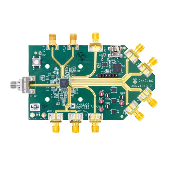
EVALUATION BOARD PHOTOGRAPH
Figure 1.
Rev. B | Page 1 of 19
ADMV1013-EVALZ
GENERAL DESCRIPTION
The ADMV1013-EVALZ evaluation board incorporates the
ADMV1013
with a microcontroller, low dropout (LDO)
regulators, and the
AD5601
easy evaluation of the ADMV1013. The microcontroller allows
the user to configure the
ADMV1013
Analysis, Control, Evaluation
allow the
ADMV1013
to be powered on by a single supply, and
offer power supply ripple rejection. The
allows the user to attenuate the radio frequency (RF) power
from the mixer of the
ADMV1013
power supply.
The
ADMV1013
is a silicon germanium (SiGe) design, wideband,
microwave upconverter optimized for point to point microwave
radio designs operating in a frequency range of 24 GHz to 44 GHz.
The
ADMV1013
comes in a compact, thermally enhanced,
6 mm × 6 mm LGA package, and operates over a temperature
range of −40°C to +85°C. For full details on the ADMV1013, see
the
ADMV1013
data sheet. Consult the data sheet in conjunction
with this user guide when using the ADMV1013-EVALZ
evaluation board.
User Guide
UG-1461
nanoDAC® to allow the quick and
register map through the
(ACE) software. The LDO regulators
AD5601
nanoDAC
without using an external
Advertisement
Table of Contents

Subscribe to Our Youtube Channel
Related Manuals for Analog Devices ADMV1013-EVALZ


Summary of Contents for Analog Devices ADMV1013-EVALZ
-
Page 1: Features
−40°C to +85°C. For full details on the ADMV1013, see ADMV1013 data sheet ADMV1013 data sheet. Consult the data sheet in conjunction SOFTWARE NEEDED with this user guide when using the ADMV1013-EVALZ evaluation board. software ADMV1013 plugins ADMV1013-EVALZ USB driver EVALUATION BOARD PHOTOGRAPH Figure 1. -
Page 2: Table Of Contents
UG-1461 ADMV1013-EVALZ User Guide TABLE OF CONTENTS Features ....................1 Installing the ACE Software, ADMV1013 Plugins, and ADMV1013 USB Drivers ..............6 Evaluation Kit Contents ..............1 Initial Setup ..................7 Equipment Needed ................1 ADMV1013 Block Diagram and Functions ........8 ... -
Page 3: Evaluation Board Hardware
(Register 0x09, Bits[3:0]). I_N, Q_P, and Q_N, to an I/Q baseband generator, and use Jumper J1 to Jumper J4 with the I/Q inputs. The ADMV1013-EVALZ The LO path operates differentially or single-ended. LOP and evaluation board operates on a 5 V dc supply. Figure 4 shows the LON are the inputs to the LO path. -
Page 4: Changes To Figure 4 And Figure 6
LO INPUT 180° HYBRID FOR DIFFERENTIAL LO LO_P LO_N DAC OR BASEBAND GENERATOR SPECTRUM ANALYZER RF_OUT BASEBAND INPUTS DC POWER SUPPLY +5V DC Figure 6. ADMV1013-EVALZ Lab Bench Setup for the I/Q Inputs Rev. B | Page 4 of 19... -
Page 5: Changes To Figure 7
IF_I IF INPUT SPECTRUM ANALYZER RF FREQUENCY GENERATOR RF_OUT 90° HYBRID FOR SINGLE-ENDED TO QUADRATURE DC POWER SUPPLY IF INPUT IF_Q +5V DC Figure 7. ADMV1013-EVALZ Lab Bench Setup for the IF Inputs Rev. B | Page 5 of 19... -
Page 6: Evaluation Board Software Quick Start Procedures
ADMV1013 Plugin from Software When the installations are complete and the software starts, the ADMV1013-EVALZ plugin appears (see Figure 10). Figure 8. Drivers Required with Installing the USB Driver After the software is installed, take the following steps to install the... -
Page 7: Changes To Initial Setup Section
INITIAL SETUP When the ADMV1013-EVALZ plugin is double clicked, the ADMV1013-044718 RevA tab shown in Figure 12 To set up the ADMV1013-EVALZ evaluation board, take the opens. On the left side of the window, open the INITIAL following steps: CONFIGURATION section, click Gain Setup, and enter... -
Page 8: Changes To Table 1
Enable is highlighted, the PARITY_EN bit is enabled. When Parity Enable is not highlighted, the PARITY_EN bit is disabled. For proper functionality of the ADMV1013-EVALZ evaluation board, it is recommended to always keep Parity Enable highlighted. Rev. B | Page 8 of 19... - Page 9 ADMV1013-EVALZ User Guide UG-1461 Label Function Click Bandgap Power Down (Label F3), and then click Apply Changes to set the BG_PD bit (Bit 10, Register 0x03). When Bandgap Power Down is highlighted, the band gap is powered down. When the Bandgap Power Down button is not highlighted, the band gap is powered up.
- Page 10 UG-1461 ADMV1013-EVALZ User Guide Label Function U1 to U2 Use the detector as follows: Click Detector Enable (Label U1), and then click Apply Changes to set the DET_EN bit (Bit 5, Register 0x03) and turn on the detector. When Detector Enable is highlighted, the DET_EN bit is enabled. When Detector Enable is highlighted, the DET_EN bit is disabled.
-
Page 11: Ctrl Voltage For The
VCTRL1 and CTRL CTRL VCTRL2 Voltage (mV) box, or type the corresponding decimal The ADMV1013-EVALZ evaluation board comes with the number for an 8-bit register in the Equivalent Decimal Value AD5601 nanoDAC. The AD5601... -
Page 12: Test Results
UG-1461 ADMV1013-EVALZ User Guide TEST RESULTS The following results test results of the ADMV1013-EVALZ Figure 17 shows the results of an IF input of 1000 MHz at evaluation board are the expected results. V = 1800 mV is used −10 dBm, single tone mixed, with a 7 GHz LO at 0 dBm to an CTRL for both the IF results and the I/Q results. -
Page 13: Changes To Figure 19
ADMV1013-EVALZ User Guide UG-1461 EVALUATION BOARD SCHEMATICS AND ARTWORK LO_P LO_N 25-146-1000-92 4 3 2 25-146-1000-92 AGND AGND 3.3V_1013 SEN1 C341 33Ω 1.8V 0.01µF 10µF 100pF AGND AGND AGND B3S-1000 0.01µF 100pF 10µF AGND AGND AGND 1.1kΩ AGND SCLK AGND 3.3V_1013... -
Page 14: Changes To Figure 19
UG-1461 ADMV1013-EVALZ User Guide 10µF 0.1µF 0.1µF 0.1µF 0.1µF C3216 C0402 C0402 C0402 C0402 AGND 3.3V PROGRAMMING HEADER TSW-106-08-G-S 80.6Ω R1206 XC12 10µF C0603 AGND 10kΩ LB L293-N1N2-25-Z (BLUE) R0603 PIC18F24J50-I/ML VDDCORE_VCAP VUSB RA1_AN1_C2INA_RP1 MCLR_N RA0_AN0_C1INA_ULPWU_RP0 RA2_AN2_VREF_NEG_CVREF_C2INB RB7_KBI3_PGD_RP10 RA3_AN3_VREF_POS_C1INB RB6_KBI2_PGC_RP9... - Page 15 4.7µF 0.001µF 0.001µF AGND AGND AGND C0603 C0603 C0603 AGND AGND AGND AGND AGND 3.3V_1013 3.3V Figure 21. LDO Regulator Connections Figure 22. ADMV1013-EVALZ Evaluation Board Top Figure 23. ADMV1013-EVALZ Evaluation Board Bottom Rev. B | Page 15 of 19...
-
Page 16: Changes To Figure 23
NOTES 1. SILKSCREEN MIGHT BE SLIGHTLY DIFFERENT DEPENDING ON THE REVISION OF THE BOARD. Figure 24. ADMV1013-EVALZ Evaluation Board Printed Circuit Board (PCB), Top Layer Figure 25. ADMV1013-EVALZ Evaluation Board PCB, Second Layer Rev. B | Page 16 of 19... -
Page 17: Changes To Figure 24
ADMV1013-EVALZ User Guide UG-1461 Figure 26. ADMV1013-EVALZ Evaluation Board PCB, Third Layer NOTES 1. SILKSCREEN MIGHT BE SLIGHTLY DIFFERENT DEPENDING ON THE REVISION OF THE BOARD. Figure 27. ADMV1013-EVALZ Evaluation Board PCB, Bottom Layer Rev. B | Page 17 of 19... -
Page 18: Configuration Options
AD5601 nanoDAC Not applicable ADMV1013 device under test Not applicable PCB, ADMV1013-EVALZ Not applicable The ADMV1013-EVALZ evaluation board material between Layer 1 and Layer 2 is made of 10.7 mil Rogers 4350B LoPRo®. Rev. B | Page 18 of 19... -
Page 19: Changes To Table 2
By using the evaluation board discussed herein (together with any tools, components documentation or support materials, the “Evaluation Board”), you are agreeing to be bound by the terms and conditions set forth below (“Agreement”) unless you have purchased the Evaluation Board, in which case the Analog Devices Standard Terms and Conditions of Sale shall govern. Do not use the Evaluation Board until you have read and agreed to the Agreement.
Need help?
Do you have a question about the ADMV1013-EVALZ and is the answer not in the manual?
Questions and answers