Table of Contents
Advertisement
Quick Links
One Technology Way • P.O. Box 9106 • Norwood, MA 02062-9106, U.S.A. • Tel: 781.329.4700 • Fax: 781.461.3113 • www.analog.com
Using the ADN8831 TEC Controller Evaluation Board
INTRODUCTION
The
ADN8831
is a thermoelectric cooler (TEC) controller
that drives medium power TECs (<4 A current) with excellent
temperature control resolution, stability, and high power
efficiency. The ADN8831 integrates two high performance
amplifiers dedicated to temperature sensing and thermal loop
compensation, allowing direct interface to a thermistor, a resistive
temperature device (RTD), or other temperature sensors.
When used in conjunction with the ADN8831 data sheet, this
application note describes how to configure the ADN8831-EVALZ
evaluation board (Version 4.0), and how to develop a real TEC
control circuit with an ADN8831. The ADN8831 data sheet
provides the detailed technical specifications and internal
functional block diagrams, as well as the application design
guidelines.
Important layout design guidelines are available in the
Evaluation Board Layout section of this application note.
FUNCTIONAL BLOCK DIAGRAM
ADN8831 EVALUATION BOARD
SETPOINT
VOLTAGE LIMIT
TEMPERATURE
CONFIGURATION
RANGE
LED
POTENTIOMETERS
CONFIGURATION
POTENTIOMETERS
ADN8831
SETPOINT
TEMPERATURE
ADJUSTMENT
STANDBY
POTENTIOMETER
TUNABLE
COMPENSATION NETWORK
Figure 1. Functional Block Diagram of ADN8831 Evaluation Board
Rev. C | Page 1 of 12
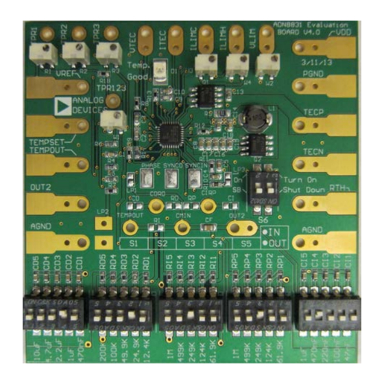
EVALUATION BOARD DESCRIPTION
The ADN8831 evaluation board offers a configurable design
platform to work with various TECs and thermistors. On the
evaluation board, the ADN8831 delivers and controls a bidirec-
tional TEC current using two pairs of complementary MOSFETs
in an H-bridge configuration.
With the on-board, adjustable components, the evaluation
board provides configurability of temperature setpoint, tem-
perature setpoint range, TEC current and/or voltage limits, and
a PID compensation network. The temperature setpoint range
(factory default) circuit, optimized to work with 10 kΩ negative
temperature coefficient thermistors, can also work with other
types of temperature sensors. The tunable PID compensation
network allows the characteristic matching between the control
circuit and the thermal load for achieving the fastest response
time and temperature control stability. A green LED illuminates
when the TEMOUT voltage is within ±100 mV of the TEMPSET
setpoint voltage.
CURRENT AND
POWER
SUPPLY
TEC
ON
ON
OFF
THERMISTOR
EXTERNAL
COMPONENTS
AN-695
APPLICATION NOTE
Advertisement
Table of Contents

Related Manuals for Analog Devices ADN8831


Summary of Contents for Analog Devices ADN8831
-
Page 1: Introduction
(RTD), or other temperature sensors. board provides configurability of temperature setpoint, tem- When used in conjunction with the ADN8831 data sheet, this perature setpoint range, TEC current and/or voltage limits, and application note describes how to configure the ADN8831-EVALZ a PID compensation network. -
Page 2: Table Of Contents
AN-695 Application Note TABLE OF CONTENTS Introduction ..................1 Set the Output Voltage Limit ............6 Evaluation Board Description............1 Monitor the TEC Voltage .............6 Functional Block Diagram .............. 1 Monitor the TEC Current ............6 Getting Started .................. 3 Temperature Compensation ............6 Switches and Potentiometers ............ -
Page 3: Getting Started
The ADN8831-EVALZ, shown in Figure 2, is set by factory default to deliver about 2 A bidirectional TEC current while The ADN8831 is placed in standby mode when Switch S6 (the working with a 10 kΩ thermistor at 25°C. left hand side knob) is down. When the knob is up (default), the ADN8831 is released from standby mode. -
Page 4: Quick Start
Connect the power supply, the TEC module, and the thermistor TEMPOUT resistance dependent. V is a function of R , R1, R2, and to an ADN8831-EVALZ as shown in Figure 5 and as described TEMPOUT R3 as in Step 1 through Step 6. ... -
Page 5: Configure The Setpoint Temperature
Application Note AN-695 Because these potentiometers connect to the active components CONFIGURE THE SETPOINT TEMPERATURE inside the ADN8831, the measured result is not accurate if the The V voltage corresponds to a TEC setpoint temperature. TEMPSET internal components conduct a significant leakage current. -
Page 6: Set The Output Voltage Limit
When the ADN8831 is set to standby mode, knowing the voltage Set CI to 1 μF, RI and RP to 249 kΩ, RD to 100 kΩ, and CD across the TEC is useful. This voltage, called the Seebeck voltage, is to 470 nF. -
Page 7: Adjust The Pwm Switching Frequency
MULTIPLE UNIT EVALUATION work components with the discrete components to be used The ADN8831 can drive one TEC or, in a multiple unit configure- in the future system and repeat the test. After soldering the tion, can drive multiple TECs. Details for connecting multiple discrete components, turn off the tunable compensation net- devices together are available in the ADN8831 data sheet. -
Page 8: Evaluation Board Layout
AN-695 Application Note EVALUATION BOARD LAYOUT Figure 10 through Figure 13 show the layout of the ADN8831 that occurs when a high frequency signal interferes evaluation board. with a low frequency circuit; the interference signal is rectified, or coupled, onto dc or lower frequency signals, Seven important guidelines are helpful when designing an thus affecting the operation of the circuit. -
Page 9: Evaluation Board Schematic And Artwork
(Version 4.0). Note that THPAD, shown as Pin 33 in this schematic, refers to the exposed thermal pad underneath the chip set. Connect THPAD to AGND to dissipate heat. Figure 9. ADN8831 Evaluation Board Schematic Rev. C | Page 9 of 12... - Page 10 AN-695 Application Note Figure 10. Top Layer Silkscreen Figure 11. Middle Layer 1 Layout Rev. C | Page 10 of 12...
- Page 11 Application Note AN-695 Figure 12. Middle Layer 2 Layout Figure 13. Bottom Layer Layout Rev. C | Page 11 of 12...
- Page 12 LG T67K-H2K1-24-Z Switch, 2PST C&K SDA02H1SBD S1, S2, S3, S4, S5 Switch, 5PST C&K SDA05H1SBDA ©2013 Analog Devices, Inc. All rights reserved. Trademarks and registered trademarks are the property of their respective owners. AN04592-0-5/13(C) Rev. C | Page 12 of 12...
Need help?
Do you have a question about the ADN8831 and is the answer not in the manual?
Questions and answers