Table of Contents
Advertisement
INST-006/009P_R13
05/2020
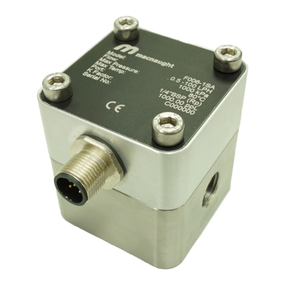
OVAL GEAR FLOWMETER
ELECTRONIC MODEL 006/009 (¼‖)
To the Owner
PLEASE READ THIS SAFTEY INFORMATION
CAREFULLY BEFORE USE.
Read and retain this instruction manual to assist you
in the operation and maintenance of this product.
If you have any problems with the meter, refer to the
maintenance and trouble shooting sections of this
manual.
This manual contains connection and operating in-
structions for meters with Pulse outputs.
Models with a Liquid Crystal Display have an addi-
tional LCD instruction manual supplied. If you need
further assistance, contact your local representative
or distributor for advice.
INSTRUCTION MANUAL— ‗M' Series 006/009 Meters
This Flow Meter has incorporated the oval rotor prin-
cipal into its design. This has proven to be a reliable
and highly accurate method of measuring flow.
Exceptional repeatability and high accuracy over a
wide range of fluid viscosities and flow rates are
features of the oval rotor design. With a low pressure
drop and high pressure rating oval rotor flow meters
are suitable for both gravity and pump (in line)
applications.
This instruction manual covers pulse meters con-
structed in Aluminium or Stainless Steel.
Page 1 of 20
Advertisement
Table of Contents

Related Manuals for Macnaught M Series


Summary of Contents for Macnaught M Series
- Page 1 INST-006/009P_R13 05/2020 OVAL GEAR FLOWMETER ELECTRONIC MODEL 006/009 (¼‖) INSTRUCTION MANUAL— ‗M‘ Series 006/009 Meters To the Owner PLEASE READ THIS SAFTEY INFORMATION This Flow Meter has incorporated the oval rotor prin- CAREFULLY BEFORE USE. cipal into its design. This has proven to be a reliable and highly accurate method of measuring flow.
-
Page 2: Table Of Contents
index Installation Page 3 Pre-installation checks …………………………………………………………. Page 3 Operating Principle …………………………………………………………. Page 3 Installation Procedure …………………………………………………………. Maintenance Procedure Disassembly …………………………………………………………. Page 4 Page 4 Reassembly …………………………………………………………. Page 4 Exploded Diagram …………………………………………………………. Flowmeter Specifications Page 5 Flowmeter Specifications …………………………………………………………. Page 5 Pulser Specifications …………………………………………………………. -
Page 3: Pre-Installation Checks
Important Information Installation Procedure WARNING Before use, confirm the fluid to be used is com- patible with the meter. Refer to Industry fluid compatibility charts or consult your local rep- resentative for advice. To prevent damage from dirt or foreign matter it is recommended that a Y or Basket type 200 mesh strainer be installed as close as possible to the inlet side of the meter. -
Page 4: Maintenance Procedure
Maintenance Procedures Disassembly Reassembly Ensure that the fluid supply to the meter is dis- 1. Place the rotors (Item 2 & 3) on the shafts inside connected, and the line pressure is released be- the body at 90° to each other in the same way as fore disassembly, with the exception for repair or it was originally factory fitted. -
Page 5: Flowmeter Specifications
Product Specifications Flowmeter Metric Below 5 cP 2 - 100 l/hr 0.5 - 26 G/hr Flow Range 5 to 1000 cP 0.5 - 100 l/hr 0.13 - 26 G/hr 006 Flowmeter Range K-Factor (Pulses per Unit of Measure) Refer to Flowmeter Data Plate Below 5 cP 25 - 500 L/hr 6.6- 130 G/hr... -
Page 6: Wiring Instructions - If Flowmeter Fitted With Cable
Pulser Wiring Instructions - Models M,F,S and CR - If fitted with cable Note: The below wiring instructions are only valid for flowmeters fitted with cable. Read carefully Reed Switch Reed Switch is a 2-wire device which triggers by magnet inside the rotors as they spin. -
Page 7: Wiring Instructions - If Flowmeter Fitted With Din Connector
Notes Analogue Output (4-20mA) Analogue outputs are available as an auxiliary display signal by including the following LCD displays with your flow meter. These may be fitted to the meter or remote (wall mount) types. Small display with analogue output module Remote or Meter Mount Large display with analogue output module Remote Mount only... - Page 8 Pulser Wiring Instructions - Models M,F, CR and S - If fitted with DIN connector Note: The below wiring instructions are only valid for flowmeters fitted with DIN connector Wiring instructions Reed / Hall Module Pin designation M12 male connector Schematic diagram Contact designation M12 cable Schematic diagram...
- Page 9 Pulser Wiring Instructions - Models M,F, CR and S - If fitted with DIN connector Note: The below wiring instructions are only valid for flowmeters fitted with DIN connector Wiring instructions Dual Reed Module Pin designation M12 male connector Schematic diagram Contact designation M12 cable Schematic diagram Page 9 of 20...
-
Page 10: Signal Cable Specs - (M12) Din Cable
Signal cables SPECS (M12) DIN cable Note: The below wire specifications are for female DIN connector cable General Connector M12 (DIN) Standards / regulations IEC 61076-2-101 Part Number MXD-C1.5S Description 1.5 meter connection cable (straight plug/socket) Technical Specifications (Plug and socket) Number of positions Protection IP67... -
Page 11: Troubleshooting Guide
Troubleshooting Guide Problem Cause Remedy Fluid will not flow a) Foreign matter blocking rotors a) Dismantle meter, clean rotors (strainer must be fit- through meter b) Line strainer blocked ted in line) c) Damaged rotors b) Clean strainer d) Meter connections over tightened c) Replace rotors (Strainer must be fitted in line) e) Fluid is too viscous d) Re-adjust connections... -
Page 12: Spare Parts Kits
Spare Parts Kits - Type M,F,S and CR There are 3 Spare Kit options available for the purchase of replacement components: Pulser Kit (PKit) - Replacement Pulser Cap Rotor Kit (RKit) - Complete Rotor assembly Seal Kit (SKit) - Complete set of O-Rings/Gaskets spare kits Series 006 F006... -
Page 13: Meter Cap Torques
Spare kit Coding Procedure 1. Determine what type of Spare Parts Kit is required (e.g. Rotor Kit) 2. Use the ‘Coding Sequence’ to construct a part number according to the meter type. Pulser Kit - (for models M,F,S and CR) - If fitted with cable —... - Page 14 Pulser Kit - (for models M,F,S and CR) - If fitted with DIN connector — Customer Model Number Coding Sequence (Reed/Hall) RH PKit — Size — (Reed/Reed) RR Kit Components Order Number Components Items Pulser Cap PKit – F006/009 – RH Bolts Seal O-ring NOTE:...
- Page 15 Rotor Kit - (for Models M,F,S and CR) - If fitted with cable — Customer Model Number Coding Sequence RKit — Type Size — Order Number Components Items Kit Components Complete Rotor Assembly 1 set RKit – F006 – SP Meter Body O-Rings Meter Cap Screws NOTE:...
-
Page 16: Wetted Parts
Wetted Parts Model 006 Component Type 'F' Type 'S' Type 'M' Type 'CR' Meter Body Meter Cap Rotor Shafts Hast C Rotors - Standard - High Temp. Rotor Bushes O-Ring FFKM FFKM FFKM Model 009 Component Type 'F' Type 'S' Type 'M' Type 'CR' Meter Body... - Page 17 Pressure Drop v’s Viscosity 100% 100% Page 17 of 20...
- Page 18 Meter Dimensions 006 Dimensions of DR/DRA register—If meter 006 is fitted with one of these Page 18 of 20...
- Page 19 Meter Dimensions 009 Dimensions of DR/DRA register—If meter 009 is fitted with one of these Page 19 of 20...
- Page 20 The WEEE Directive requires the recycling of waste electrical and electronic equip- ment in the European Union. Whilst the WEEE Directive does not apply to some of Macnaught’s products, we sup- port its policy and ask you to be aware of how to dispose of this product.
Need help?
Do you have a question about the M Series and is the answer not in the manual?
Questions and answers