Table of Contents
Advertisement
MXL-INST
Rev 8
10/2017
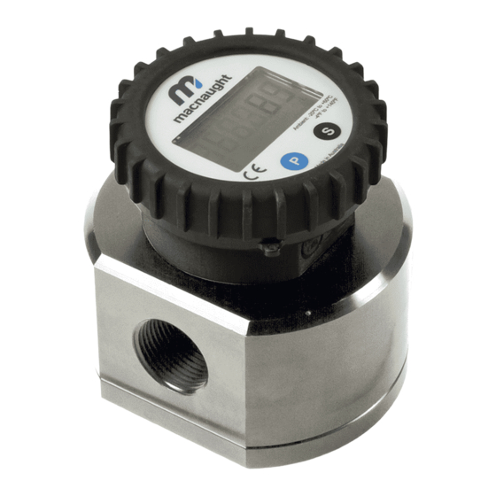
OVAL GEAR FLOWMETER SERIES
To the Owner
Please read and retain this instruction manual to
assist you in the operation and maintenance of this
product.
This manual contains connection and operating in-
structions for the MX series Flow Meters with Pulse
outputs.
Models with a Liquid Crystal Display have an addi-
tional LCD instruction manual supplied. If you need
further assistance, contact your local representative
or distributor for advice.
This Flow Meter has incorporated the oval gear prin-
cipal into its design. This is proven to be a reliable
and highly accurate method of measuring flow.
Exceptional repeatability and high accuracy over a
wide range of fluid viscosities and flow rates are
features of the oval gear design.
With a low pressure drop and high pressure rating
oval gear flow meters are suitable for both gravity
and (in-line) pump applications.
MX06 - MX100
INSTRUCTION MANUAL
Macnaught offer a comprehensive set web based
support materials to compliment this instruction
manual.
Access the website by scanning the QR code below.
WWW.MACNAUGHT.COM.AU
Page 1 of 38
Advertisement
Table of Contents

Related Manuals for Macnaught MX06S


Summary of Contents for Macnaught MX06S
- Page 1 OVAL GEAR FLOWMETER SERIES INSTRUCTION MANUAL To the Owner Please read and retain this instruction manual to Macnaught offer a comprehensive set web based assist you in the operation and maintenance of this support materials to compliment this instruction product.
-
Page 2: Table Of Contents
index Installation Page 3 Pre-installation checks …………………………………………………………. Page 3 Operating Principle …………………………………………………………. Page 3 Installation Procedure …………………………………………………………. Maintenance Procedure Page 4 Disassembly …………………………………………………………. Page 4 Reassembly …………………………………………………………. Flowmeter Specifications Page 5-8 Flowmeter Specifications …………………………………………………………. Page 9 Wiring Diagram - Standard Pulser …………………………………………………………. -
Page 3: Pre-Installation Checks
IMPORTANT INFORMATION INSTALLATION PROCEDURE FLUID COMPATABILITY Before use, confirm the fluid to be used is compatible with the meter. Refer to Industry fluid compatibility charts or consult your local representative for advice. STRAINER To prevent damage from dirt or foreign matter 1. -
Page 4: Maintenance Procedure
MAINTENANCE PROCEDURE 4. Smear the O-Ring with a light film of grease. DISASSEMBLY Replace the O-Ring into groove in the meter cap. Note: Maintenance can be carried out to the liquid The O-Ring will need to be replaced if it has crystal displays and pulse output modules without grown or is damaged in anyway. -
Page 5: Flowmeter Specifications
(Sensor Pulses per Unit of Measure) Refer to Flowmeter Data Plate Max Temperature (model MX06F) -20°C - 80°C -4°F - 176°F (models MX06S) -40°C - 120°C -40°F - 248°F (models MX06P) -40°C - 150°C -40°F - 302°F Maximum Operating Pressure... - Page 6 FLOWMETER SPECIFICATIONS series MX19 Metric Below 5 cP 8 to 70 LPM 2 to 18.5 GPM Flow Range 5 to 1000 cP 3 to 80 LPM 0.8 to 21 GPM K-Factor (Sensor Pulses per Unit of Measure) Refer to Flowmeter Data Plate Max Temperature (model MX19F) -20°C - 80°C...
- Page 7 FLOWMETER SPECIFICATIONS series MX50 Metric Below 5 cP 15 to 500 LPM 4 to 130 GPM Flow Range 5 to 1000 cP 15 to 500 LPM 4 to 130 GPM K-Factor (Sensor Pulses per Unit of Measure) 6.7 pulses/L 25.36 pulses/G Max Temperature (model MX50F) -20°C - 80°C...
- Page 8 FLOWMETER SPECIFICATIONS High Viscosity Applications Ensure the Flowmeter is fitted with ‘High Viscosity Rotors’ if the fluid being metered is 1000 cP or above High Viscosity Rotors For Fluids above 1000 Centipoise (cP) DIGITAL DISPLAYS The MX Flow meter series is supplied with either a Compact Pulser and Digital Display option. Please note the wiring diagrams in the following pages are for the Compact Pulser Output Modules and the PCB (Sensor Board), which is responsible for providing a Raw Pulse input to the LC display If the Flow meter is supplied with an LC Display fitted, please consult the appropriate Instruction Manual, as...
-
Page 9: Wiring Diagram - Standard Pulser
WIRING DIAGRAM 1 Output type A,D,E,F,G,H Pulser Specifications Output Signals Standard Pulse Meter 2x Digital (Square Wave) Current Maximum 500mA Reed Switch Voltage Maximum 30V DC (Mechanical Sensor) Contact Rating Maximum Maximum Supply Current 7.5mA Maximum Output Current 25mA Hall Effect IC (Electronic Sensor) Operating Voltage 4.5V to 24V DC... -
Page 10: Wiring Diagram - Pcb Sensor
WIRING DIAGRAM 1 Output types A,D,E,F,G,H Reed Switch To maximise the life of the reed switch contacts, the pulse board comes equipped with a 1k8Ω current limiting resistor in series with the reed switch as standard. NPN Open Collector Hall Effect Sensor The output for the hall effect sensor is NPN (current sinking, open collector). -
Page 11: Wiring Diagram - High Temp Sensor (-Ht)
WIRING DIAGRAM 3 High Temperature Output type ‘T’ Pulser Specifications SENSOR TYPE OMNI POLAR Construction Stainless Steel Housing Operating Voltage 4.5 to 30V DC SPECIFICATIONS Maximum Supply Current 18mA -40 - 150°C Temperature Range -40 - 302°F Page 11 of 38... -
Page 12: Troubleshooting Guide
Check wiring connections MAINTAINENCE VIDEOS Macnaught provides an comprehensive set of ‘Maintenance Videos’ to assist the end user in all aspects of service and/or repair of the Flowmeter range. This web based resource can be accessed via the following URL http://www.macnaught.com.au/mx_resources... -
Page 13: Exploded Diagrams
EXPLODED DIAGRAM models MX06-MX50 PARTS IDENTIFICATION METER COMPONENTS ITEM NO. CIRCLIP METER BODY METER CAP O-RING MAGNET HOUSING MAGNETS ROTORS ROTOR SHAFTS METER CAP METER CAP SCREWS Page 13 of 38... - Page 14 EXPLODED DIAGRAM models MX75-MX100 PARTS IDENTIFICATION PART DESCRIPTION Item No. Meter Body Rotor Shafts Rotors Meter Cap O-Ring Meter Cap Circlip Meter Cap Bolts Flange Seals Process Connection (Flanged or Threaded) Flange Washers Flange Bolts Page 14 of 38...
-
Page 15: Meter Cap Torques
METER TORQUE Meter Torque Ratings Pressure Series Torque (Nm) Lubrication (psi) MX06 1000 1000 6.5 Nm MX09 2000 MX12 2000 MX19 15 Nm 2000 MX25 MX40 1500 MX50 1200 33 Nm MX75 MX100 SPARE PARTS KITS Spare Kit options, for both Flowmeter and Display/Pulser modules, are available as replacement components. ... - Page 16 SPARE PARTS KITS MX06F MX06S MX06P spare kits Series MX06 MXS06F-rotor MXS06S-rotor MXS06P-rotor Standard ROTOR KIT MXS06P-HTrotor High Temp MXS06F-seal MXS06S-seal MXS06P-seal SEAL KIT MX09F MX09S MX09P spare kits Series MX09 MXS09F-rotor MXS09S-rotor MXS09P-rotor Standard MXS09S-HVrotor MXS09P-HVrotor ROTOR KIT High Viscosity...
- Page 17 SPARE PARTS KITS spare kits Series MX40 MX40F MX40S MX40P MXS40F-rotor MXS40S-rotor MXS40P-rotor Standard MXS40S-HVrotor MXS40P-HVrotor ROTOR KIT High Viscosity MXS40P-HTrotor High Temp MXS40F-seal MXS40S-seal MXS40P-seal SEAL KIT MX50F MX50S MX50P spare kits Series MX50 MXS50F-rotor MXS50S-rotor MXS50P-rotor Standard MXS50S-HVrotor MXS50P-HVrotor ROTOR KIT High Viscosity...
-
Page 18: Wetted Parts
WETTED PARTS Wetted parts series MX06 MX06F MX06S MX06P METER BODY Alum Alum St.St METER CAP Alum Alum St.St ROTORS Standard St.St High Temp St. St ROTOR SHAFTS St.St St.St St.St ROTOR BUSHES O-RINGS Wetted parts series MX09 MX09F MX09S... - Page 19 WETTED PARTS Wetted parts series MX19 MX19F MX19S MX19P METER BODY Alum Alum St.St METER CAP Alum Alum St.St ROTORS - Standard St.St High Viscosity St.St. St.St High Temp St. St ROTOR SHAFTS St.St St.St St.St ROTOR BUSHES O-RINGS Wetted parts series MX25 MX25F MX25S MX25P...
- Page 20 WETTED PARTS Wetted parts series MX50 MX50F MX50S MX50P METER BODY Alum Alum St.St METER CAP Alum Alum St.St ROTORS - Standard Alum High Viscosity Alum St.St High Temp St. St ROTOR SHAFTS St.St St.St St.St ROTOR BUSHES O-RINGS Wetted parts series MX75 MX75F MX75S MX75P...
- Page 21 WETTED PARTS K - FEP/PTFE Encapsulated SS - Stainless Steel 316 Al - Aluminium AA610 CA - Carbon FKM - Viton ® PPS - Polyphenylene Sulphide (PPS Resin) Page 21 of 38...
-
Page 22: Pressure Drop Graphs
PRESSURE DROP v VISCOSITY 100% 100% Page 22 of 38... -
Page 23: Dimensional Diagrams
DIMENSIONS series MX06-MX50 Page 23 of 38... - Page 24 WALL MOUNT ADAPTOR Series MX06 and MX09 Page 24 of 38...
- Page 25 WALL MOUNT ADAPTOR Series MX12 Page 25 of 38...
- Page 26 WALL MOUNT ADAPTORS Series MX19 Page 26 of 38...
- Page 27 WALL MOUNT ADAPTORS Series MX25 Page 27 of 38...
- Page 28 WALL MOUNT THREAD POSITION Series MX40 Page 28 of 38...
- Page 29 WALL MOUNT THREAD POSITION Series MX50 Page 29 of 38...
- Page 30 METER DIMENSIONS series MX75 Page 30 of 38...
- Page 31 DIMENSIONS MX75 with Air Eliminator 3” Flange 3” Threaded Connection Page 31 of 38...
- Page 32 METER DIMENSIONS series MX100 Page 32 of 38...
- Page 33 DIMENSIONS MX100 with Air Eliminator 4” Flange 3” Threaded Connection Page 33 of 38...
- Page 34 NOTES Page 34 of 38...
- Page 35 NOTES Page 35 of 38...
- Page 36 NOTES Page 36 of 38...
- Page 37 The WEEE Directive requires the recycling of waste electrical and electronic equip- ment in the European Union. Whilst the WEEE Directive does not apply to some of Macnaught’s products, we sup- port its policy and ask you to be aware of how to dispose of this product.
- Page 38 Note: This product should be disposed of according to all applicable local and national government environment regulations and guidelines. Page 38 of 38...
Need help?
Do you have a question about the MX06S and is the answer not in the manual?
Questions and answers