Macnaught MX Series Manual
Hide thumbs
Also See for MX Series:
- Instruction manual (32 pages) ,
- Instruction manual (16 pages) ,
- Instruction manual (28 pages)
Advertisement
Quick Links
MXEX-IS-INST
Rev 1
04/2022
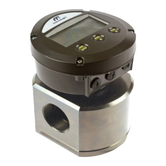
OVAL GEAR FLOWMETER
To the Owner
Please read and retain this instruction manual to assist
you in the operation and maintenance of this product.
The manual contains operating and maintenance
instructions for the MX-Series Flow Meters with Ex
outputs. This covers port sizes from 1/4" to 4".
Refer to separate instruction manual for information on
operating modes and features of LCD displays.
Contact local representative or distributor for further
assistance.
This Flow Meter has incorporated the oval gear
principle into its design. Exceptional repeatability and
high accuracy over a wide range of fluid viscosities
and flow rates are features of the oval gear design.
MX SERIES
Intrinsically Safe with Simple Apparatus PCB
With a low pressure drop and high pressure ratings,
oval gear flow meters are suitable for gravity and
(in-line) pump applications.
Macnaught offer a comprehensive set of web based
support materials to complement this instruction
manual.
Access the Instruction manual by scanning below
QR code.
www.macnaught.com.au
Page 1 of 32
Advertisement

Related Manuals for Macnaught MX Series


Summary of Contents for Macnaught MX Series
- Page 1 (in-line) pump applications. The manual contains operating and maintenance instructions for the MX-Series Flow Meters with Ex Macnaught offer a comprehensive set of web based outputs. This covers port sizes from 1/4” to 4”. support materials to complement this instruction manual.
- Page 2 INDEX Important Information Page # 3-4 Operating Principle Page # 5 Installation Installation Instructions Page # 5-6 Earthing Points on Flow meter Page # 6 Maintenance Procedure Disassembly Page # 7 Reassembly Page # 7 Pictorial Representation Page # 8 Flow meter Specifications Product Identification System Page # 9...
- Page 3 (READ CAREFULLY) EQUIPMENT CATEGORY: The Macnaught oval gear flow meters are designed in category II 2 G according to EN 60079-0 and EN 60079-11 for use in zone 1. The inside of the measuring unit is also approved for zone 1.
- Page 4 Any alteration to the product (e.g. removal of the 3 plugs (IP67) on the housing, installation of cable glands, etc) may result in a deterioration of explosion protection and an increased risk of explosion. Macnaught will not accept any liability resulting from alterations to the product.
- Page 5 OPERATING PRINCIPLE Fluid passing through the meter causes the rotors to turn, as shown below. One of the rotors (the active rotor) is fitted with magnets. The passing of the magnets are picked up by the electronic sensor. The excitation of this switch provides a ‘Raw Pulse Output’...
- Page 6 INSTALLATION INSTRUCTIONS 1. It is recommended that a bypass line be included in the design. This provides the facility for a meter The flow meter can accept flow in any direction. removed maintenance without interrupting production. (see figure) 5. The meter can be installed in any orientation as long as the meter shafts are in a horizontal plane as per the picture.
- Page 7 1. Before reassembling, check the condition of flow meter parts (rotors, body, cap, seal O-ring and shafts). Re place if necessary. Contact Macnaught to check for spare parts availability. 2. One of the rotors is active (have magnets) and other one is neutral. The active rotor can be identified by running a metal object over the face of the rotor.
- Page 8 PICTORIAL REPRESENTATION OF FLOWMETER AND DISASSEMBLED PARTS Flow meter FIG 1 Flow Meter Cap FIG 2 Shafts Dimple Flow meter Body FIG 3 Groove Dimple Rotors Chamfer Area Rotors (At 90°) FIG 6 FIG 4 Active Neutral Rotor Rotor For MX06 and MX09 meters, the flat side of rotors with chamfer edges...
- Page 9 PRODUCT IDENTIFICATION SYSTEM 1/4” 1/4” 1/2” 3/4” 1” 1 1/2” 2” 3” 4” SS/SS/FEP MX06-MX50 SS/PEEK/FEP AL/SS/FEP MX06 - MX25 AL/PEEK/FEP AL/AL/FEP MX40 - MX100 AL/PEEK/FEP G threads MX06-MX100 3" BSP and NPT port connection for MX100 NPT threads ANSI 150# Flanges JIS 10k Flanges MX25 - MX100 DIN PN 16k Flanges...
- Page 10 FLOWMETER SPECIFICATIONS Flow Range Flow Range Flow Meter < > (Viscosity 5 cP) (Viscosity 5 cP) Series Metric Metric MX06 2 to 100 LPH 0.5 to 26 GPH 0.5 to 100 LPH 0.13 to 26.4 GPH MX09 25 to 500 LPH 6.6 to 132 GPH 15 to 500 LPH 4 to 132 GPH...
- Page 11 SIMPLE APPARATUS PCB (MX1R-IS) The flowmeter is fitted with Simple Apparatus PCB (MX1R-IS) that conforms to the demands of Intrinsically Safe environment. Simple apparatus PCB is an electronic board fitted with Dual Reed Switches with 20-25 cm of wire (Alpha wire 3464C or better) Cable fitted to Simple Apparatus PCB is non-extendable Do not connect reed switch to any external device...
- Page 12 Flow rate, total (resettable) and accumulat- ed total (non-resettable). This display is IECEx, ATEX, CSA Canada and FM USA certified. Locally mount to Macnaught Oval Gear Flowmeter with a Simple Apparatus The flowmeter with Simple Apparatus PCB and Intrinsically Safe display is IP67 rated...
- Page 13 Intrinsically Safe ERX display (Flow Indicator/Totalizer) Type (Fx) For Programming, press PROG/ENTER button for 7 seconds. Press CLEAR button to access functions and Press SELECT button to reach sub-functions Setting up a value in sub function, press PROG and get use of buttons CLEAR & SELECT to adjust a value Once the desired value is adjusted, press PROG button to finalize it Once all sub functions are set, press PROG button for 3 seconds to go back to operational mode SETUP FUNCTIONS AND VARIABLES...
- Page 14 (non-resettable). The output include a 4-20mA and scaled pulse output. This display is IECEx, ATEX, CSA Canada and FM USA certified. Locally mount to Macnaught Oval Gear Flowmeter with a Simple Apparatus The flowmeter with Simple Apparatus PCB and Intrinsically Safe display is IP67 rated...
- Page 15 Intrinsically Safe ERAX display (Flow Indicator/Totalizer) Intrinsically Safe ERAX display (Flow Indicator/Totalizer with Outputs) Type (Gx) Type (Gx) For Programming, press PROG/ENTER button for 7 seconds. Press CLEAR button to access functions and Press SELECT button to reach sub-functions. Setting up a value in sub function, press PROG and get use of but- tons CLEAR &...
- Page 16 1 x NPN type transistor, for single stage batching applications. This display is IECEx, ATEX, CSA Canada and FM USA certified. Locally mount to Macnaught Oval Gear Flowmeter with a Simple Apparatus The flowmeter with Simple Apparatus PCB and Intrinsically Safe display is IP67 rated...
- Page 17 Intrinsically Safe ERBX Batch Controller with 1 x transistor output Type (Hx) For Programming, press PROG/ENTER button for 7 seconds. Press STOP button to access functions and Press START button to reach sub-functions Setting up a value in sub function, press PROG and get use of buttons START & STOP to adjust a value Once the desired value is adjusted, press PROG button to finalize it Once all sub functions are set, press PROG button for 3 seconds to go back to operational mode SETUP FUNCTIONS AND VARIABLES...
- Page 18 Flow meter Specs / Data Plate MX75-MX100: Serial number, Model number, MX06-MX50: Serial number, Model number, k-factor, k-factor, flow rate range and temperature details are flow rate range and temperature details are engraved on flow meter data plate. See below FIG engraved on meter body.
- Page 19 EXPLODED DIAGRAM (Models MX06-MX50) METER COMPONENTS ITEM NO Display CIRCLIP METER BODY ROTOR SHAFTS ROTORS METER CAP METER CAP SCREWS EXPLODED DIAGRAM (Models MX75-MX100) METER COMPONENTS ITEM NO METER COMPONENTS ITEM NO METER BODY CIRCLIP ROTOR SHAFTS METER CAP BOLTS ROTORS FLANGE SEALS METER CAP O-RING...
- Page 20 Faulty connection from LC Display MAINTAINENCE VIDEOS Macnaught provides an comprehensive set of ‘Maintenance Videos’ to assist the end user in all aspects of service and / or repair of the flow meter range. This web based resource can be accessed by scanning the QR.
- Page 21 WETTED PARTS Wetted Parts MX06P MX09P - MX12P MX19P - MX50P MX75P - MX100P METER BODY SS 316 SS 316 SS 316 METER CAP SS 316 SS 316 SS 316 ROTORS SS 316 SS 316 SS 316/PEEK HIGH VISCOSITY ROTORS SS 316 SS 316 ROTOR SHAFTS...
- Page 22 MXS-25S-SEAL MX40S MXS-40S-ROTOR MXS-40S-HVROTOR MXS-40S-PROTOR MXS-40S-SEAL MX50S MXS-50S-ROTOR MXS-50S-HVROTOR MXS-50S-PROTOR MXS-50S-SEAL MX75S MXS-75S-ROTOR MXS-75S-HVROTOR MXS-75S-SEAL MX100S MXS-100S-ROTOR MXS-100S-HVROTOR MXS-100S-SEAL - Currently Unavailable To check for more service kits, Contact Macnaught. Contact Macnaught for available display kits Page 22 of 32...
- Page 23 PRESSURE DROP v VISCOSITY 100% Page 23 of 32...
- Page 24 16 flanges are raised faced (RF) while JIS 10k MX40 240* flanges are flat faced (FF) by default. Contact MX50 264* Macnaught if a different configuration is required. DIMENSIONS Flow Meters MX75 DIMENSIONS Flow Meters MX100 Page 24 of 32...
- Page 25 DIMENSIONS Flowmeter Registers Page 25 of 32...
- Page 26 WALL MOUNT ADAPTOR (MX06 - MX25) Meters (Ø mm) (Ø mm) (mm) (mm) (mm) (mm) (mm) (Ø mm) (mm) (mm) (Ø mm) MX06 - MX09 M5x0.8 MX12 M5x0.8 MX19 M6x1.0 MX25 M6x1.0 Wall Mount Holes (4) SS Countersunk screws to be supplied with the wall mount bracket 5 mm in diameter and 16 mm in length for MX06 - MX12 meters 6 mm in diameter and 20 mm in length for MX19 - MX25 meters Earthing Point...
- Page 27 WALL MOUNT THREAD POSITION ON FLOWMETER’S CAP (MX06 - MX50) Meters MX06 M5 x 0.80 MX09 M5 x 0.80 MX12 M5 x 0.80 MX19 M6 x 1.00 MX25 M6 x 1.00 MX40 M8 x 1.25 MX50 M8 x 1.25 Mounting Holes x 4 Earthing Points x 4 (Any of them can be used) Page 27 of 32...
- Page 28 EU Declaration of Conformity Page 28 of 32...
- Page 29 EU Declaration of Conformity Page 29 of 32...
- Page 30 Declaration of Conformity (Simple Apparatus PCB) Page 30 of 32...
- Page 31 The WEEE Directive requires the recycling of waste electrical and electronic equip- ment in the European Union. Whilst the WEEE Directive does not apply to some of Macnaught’s products, we sup- port its policy and ask you to be aware of how to dispose of this product.
- Page 32 Macnaught USA 614 S. Ware Blvd Tampa, FL 33619 Note: This product should be disposed of according to all applicable (813) 628-5506 MacnaughtUSA.com local and national government environment regulations and Page 32 of 32...
Need help?
Do you have a question about the MX Series and is the answer not in the manual?
Questions and answers