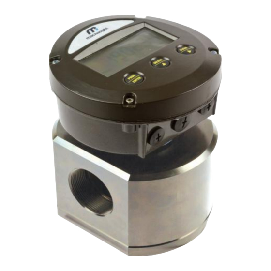
Macnaught MX Series Instruction Manual
Oval gear flowmeter
Hide thumbs
Also See for MX Series:
- Manual (32 pages) ,
- Instruction manual (28 pages) ,
- Instruction manual (16 pages)
Table of Contents
Advertisement
MXL-INST
Rev 12
12/2020
OVAL GEAR FLOWMETER
To the Owner
Please read and retain this instruction manual to
assist you in the operation and maintenance of this
product.
The manual contains operating and maintenance
instructions for the MX-Series Flow Meters. This
covers port sizes from 1/4" to 4".
Refer to separate instruction manual for information
on operating modes and features of LCD displays.
Contact local representative or distributor for further
assistance.
This Flow Meter has incorporated the oval gear
principle into its design. Exceptional repeatability and
high accuracy over a wide range of fluid viscosities
and flow rates are features of the oval gear design.
With a low pressure drop and high pressure rating
oval gear flow meters are suitable for both gravity
and (in-line) pump applications.
MX SERIES
INSTRUCTION MANUAL
Macnaught offers a comprehensive set of web based
support materials to complement this instruction
manual.
Access the Instruction manual by scanning below QR
code.
www.macnaught.com.au
Page 1 of 31
Advertisement
Table of Contents

Subscribe to Our Youtube Channel
Related Manuals for Macnaught MX Series


Summary of Contents for Macnaught MX Series
- Page 1 OVAL GEAR FLOWMETER INSTRUCTION MANUAL To the Owner Please read and retain this instruction manual to Macnaught offers a comprehensive set of web based assist you in the operation and maintenance of this support materials to complement this instruction product.
-
Page 2: Table Of Contents
Index Page 3 Important Information …………………………………………………………. Page 3 Operating Principle …………………………………………………………. Installation Page 4 Installation Procedure …………………………………………………………. Maintenance Procedure Page 4 Disassembly …………………………………………………………. Reassembly …………………………………………………………. Page 5 Page 6 Pictorial Representation …………………………………………………………. Flowmeter Specifications Page 7 Flow meter Specifications …………………………………………………………. Page 8 Flow Meter Output Types ………………………………………………………... -
Page 3: Important Information
IMPORTANT INFORMATION (READ CAREFULLY) FLUID COMPATIBILITY: Before use, confirm the fluid (liquid) to be used is compatible with the meter. Refer to industry fluid compatibility charts or consult your local representative or distributor for advice. FLOWMETER USAGE: The flow meter shall be used exclusively with liquids. No gases permitted to flow. Presence of gases could create severe hazard and damage STRAINER: To prevent damage from dirt or foreign matter, it is recommended that a Y type or Basket type mesh strainer be installed as close as possible to the inlet side of the meter. -
Page 4: Installation Procedure
INSTALLATION PROCEDURE 1. It is recommended that a bypass line be included 5. The meter can be installed in any orientation as in the design. This provides the facility for a long as the meter shafts are in a horizontal meter to be removed for maintenance without plane as per the picture. -
Page 5: Reassembly
1. Before reassembling, check the condition of flow meter parts (rotors, body, cap, seal O-ring and shafts). Re place if necessary. Contact Macnaught to check for spare parts availability. 2. One of the rotors is active (have magnets) and other one is neutral. The active rotor can be identified by running a metal object over the face of the rotor. -
Page 6: Pictorial Representation
PICTORIAL REPRESENTATION OF FLOWMETER AND DISASSEMBLED PARTS Flow meter FIG 1 Flow Meter Cap FIG 2 Shafts Dimple Flow meter Body FIG 3 Groove Dimple Rotors Chamfer Area Rotors (At 90°) FIG 6 FIG 4 Active Rotor Neutral Rotor For MX06 and MX09 meters, the flat side of rotors with chamfer edges... -
Page 7: Flowmeter Specifications
FLOWMETER SPECIFICATIONS Flow Range Flow Range Flow Meter < > (Viscosity 5 cP) (Viscosity 5 cP) Series Metric Metric MX06 2 to 100 LPH 0.5 to 26 GPH 0.5 to 100 LPH 0.13 to 26.4 GPH MX09 25 to 500 LPH 6.6 to 132 GPH 15 to 500 LPH 4 to 132 GPH... -
Page 8: Flow Meter Output Types
Flow meter Output Types Pulse output 1 x Hall Effect Switch & 1 x Reed Switch MXD-AS Dual Reed Switches MXD-IS Dual Hall Effect Switches - Quadrature Pulse MXD-JS High Resolution Sensor MXD-KS High Temperature Sensor MXD-TS Local Digital Display PR (LCD 12 mm Display) MXD-DS MXD-ES... -
Page 9: Standard Pulser Cap Details
Standard Pulse Cap Output types A, I, J, K WIRING INSTRUCTIONS Standard Pulse Cap incorporates the M-LOCK (1/4” turn) mounting system. The housing is made up of polypropylene with PCB fitted inside. Standard Pulse Cap Page 9 of 31... - Page 10 Standard Pulse Cap Output types A, I, J, K MXD-JS generate Quadrature Pulse Output MXD-KS has one hall effect high resolution sensor. Illustration Standard Pulse Cap fitted to 1” meter Assembly/Disassembly 1. Rotate the pulse cap 90° anticlockwise to disassemble 2.
- Page 11 Industrial Pulse Cap Output Type (MXD-xCx-xx) WIRING INSTRUCTIONS Industrial Pulse Cap is fixed to the flow meter and does not incorporate M-lock feature. It comes with Conduit Entry to facilitate customers for own wiring. Illustration MXD-xCx-HH generate Quadrature Pulse Output - Industrial Pulse Cap Temperature (-25 °C -120 °C) - IP 67 Cable Specifications for Standard/Industrial Pulse Cap...
-
Page 12: Industrial Pulse Cap Details
Industrial Pulse Cap Output Type (MXD-xCx-xx) Illustration Industrial Pulse Cap fitted to 1” meter Industrial Pulse Cap Housing material “Aluminium” to be fitted to flow meter having Aluminium Body Industrial Pulse Cap Housing material “SS 316” to be fitted to flow meter having SS 316 Body The Industrial Pulse Cap comprises of 3 major components. -
Page 13: Din Compact Pulse Module
DIN Compact Pulse Module Output Type (MXD-xx) DIN Compact Pulse Module incorporates the M-LOCK (¼ turn) mounting system. It provides a locking facility for added security against unauthorised removal. A locking screw is supplied with DIN compact pulse cap to accom- plish the job by fitting module to the flow meter using M-lock feature and replacing the existing screw with locking screw. - Page 14 DIN Compact Pulse Module Output Type (MXD-xx) M12 Female Cable Connector M12 Field Connector M12 male connector Cable Colour Reed / Hall Module Dual Reed Module Dual Hall Module 1 Brown HE Supply (VCC) HE Supply (VCC) 2 White HE Signal (V out) Reed Signal 1 HE Signal 1 (V out) 3 Blue...
-
Page 15: Pcb Specifications Standard/Industrial/Din
PCB Specifications Standard / Industrial Pulse Caps / DIN Compact Pulse Module Output Signals Standard Pulse Meter 2 x Digital (Square Wave) Current Maximum 500mA Reed Switch Voltage Maximum 30V DC (Mechanical Sensor) Contact Rating Maximum Maximum Supply Current 7.5mA Maximum Output Current 25mA Hall Effect Switch... -
Page 16: Specification And Wiring - High Temp Sensor
Output Type “T” High Temperature SPECIFICATIONS & WIRING SENSOR TYPE OMNI POLAR NPN with internal 3 k-Ohm pull-up resistor Construction Stainless Steel Housing (Barrel) Connector Cable Length 2 meters Operating Voltage 4.5 to 30V DC SPECIFICATIONS Maximum Supply Current 18mA -40 - 150°C Temperature Range -40 - 302°F... -
Page 17: Engraving / Data Plate Information
Flow meter Specs / Data Plate MX75-MX100: Serial number, Model number, k- MX06-MX50: Serial number, Model number, k-factor, factor, flow rate range and temperature details are flow rate range and temperature details are en- engraved on data plate. See below FIG graved on meter body. -
Page 18: Exploded Diagrams
EXPLODED DIAGRAM models MX06-MX50 METER COMPONENTS ITEM NO CIRCLIP METER BODY METER CAP O-RING MAGNET HOUSING MAGNETS ROTOR SHAFTS LOCATING PIN METER CAP METER CAP SCREWS EXPLODED DIAGRAM models MX75-MX100 METER COMPONENTS ITEM NO METER COMPONENTS ITEM NO METER BODY CIRCLIP ROTOR SHAFTS METER CAP BOLTS... -
Page 19: Troubleshooting Guide
MAINTAINENCE VIDEOS Macnaught provides an comprehensive set of „Maintenance Videos‟ to assist the end user in all aspects of service and / or repair of the flow meter range. This web based resource can be accessed by scanning the QR. -
Page 20: Spare Parts Kits
SPARE PARTS KITS SPARE PARTS KITS Rotor Kit (Rotor assembly (includes Meter Cap bolts and O-Ring) Seal Kit (O-Rings seal (includes Meter Cap Bolts) Category ROTOR KIT SEAL KIT High Viscosity Standard PEEK “ ” (Standard) MX06F MXS-06F-ROTOR MXS-06F-SEAL MX09F MXS-09F-ROTOR... - Page 21 Standard Pulse Cap (Hall/Hall) MXD-JS MXS-PCB-HH Type K Standard Pulse Cap (High Resolution Sensor) MXD-KS Type M PRM Digital 4-20 mA Blind Register MXD-MS MXS-PCB-RH Type T High Temperature Sensor MXD-TS Contact Macnaught for further assistance on service kits Page 21 of 31...
-
Page 22: Wetted Parts
WETTED PARTS Category MX06F MX09F - MX12F MX19F - MX50F MX75F - MX100F “F” METER BODY METER CAP ROTORS PPS/PEEK** HV ROTORS ROTOR SHAFTS SS 316 SS 316 SS 316 SS 316 ROTOR BUSHES CARBON O-RINGS Category MX06P MX09P - MX12P MX19P - MX50P MX75P - MX100P “P”... -
Page 23: Pressure Drop Graphs
PRESSURE DROP vs VISCOSITY 100% Page 23 of 31... -
Page 24: Dimensional Diagrams
WALL MOUNT ADAPTOR (MX06 - MX25) Wall Mount Adaptor Bracket is used to mount flow meter to the wall Dimensions (Ø mm) (Ø mm) (mm) (mm) (mm) (mm) (mm) (Ø mm) (mm) (mm) (Ø mm) MX06 - MX09 M5x0.8 MX12 M5x0.8 MX19 M6x1.0... - Page 25 WALL MOUNT THREAD POSITION ON FLOWMETER’S CAP (MX06 - MX50) MX06 M5 x 0.80 MX09 M5 x 0.80 MX12 M5 x 0.80 MX19 M6 x 1.00 MX25 M6 x 1.00 MX40 M8 x 1.25 MX50 M8 x 1.25 Mounting Holes x 4 Earthing Points x 4 (Any of them can be used) Page 25 of 31...
- Page 26 MX40 MX50 2” FLANGE TYPES: ANSI flanges 150 # and DIN PN 16 flanges are raised faced (RF) while JIS 10k flanges are flat faced (FF) by default. Contact Macnaught if a different configuration is required. Page 26 of 31...
- Page 27 MX75 3” Aluminium FLANGE TYPES: ANSI flanges 150 # and DIN PN 16 flanges are raised faced (RF) while JIS 10k flanges are flat faced (FF) by default. Contact Macnaught if a different configuration is required. Page 27 of 31...
- Page 28 FLOWMETER DIMENSIONS MX75 with Air Eliminator 3” Flange 3” Threaded Connection Page 28 of 31...
- Page 29 MX100 Aluminium 3” FLANGE TYPES: ANSI flanges 150 # and DIN PN 16 flanges are raised faced (RF) while JIS 10k flanges are flat faced (FF) by default. Contact Macnaught if a different configuration is required. Page 29 of 31...
- Page 30 FLOW METER DIMENSIONS MX100 with Air Eliminator 4” Flange 3” Threaded Connection Page 30 of 31...
- Page 31 The WEEE Directive requires the recycling of waste electrical and electronic equip- ment in the European Union. Whilst the WEEE Directive does not apply to some of Macnaught‟s products, we sup- port its policy and ask you to be aware of how to dispose of this product.
- Page 32 Macnaught Americas Macnaught Americas 614 South Ware Boulevard 614 South Ware Boulevard Tampa Florida USA, 33619 Tampa Florida USA, 33619 T: +1813 628 5506 T: +1813 628 5506 E: info@macnaughtusa.com E: info@macnaughtusa.com W: www.macnaughtusa.com W: www.macnaughtusa.com Page 32 of 31...
Need help?
Do you have a question about the MX Series and is the answer not in the manual?
Questions and answers