Macnaught MX06 Series Instruction Manual
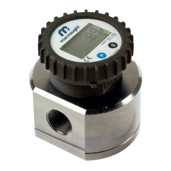
Oval gear flowmeter
Hide thumbs
Also See for MX06 Series:
- Instruction manual (28 pages) ,
- Instruction manual (32 pages) ,
- Manual (32 pages)
Advertisement
Quick Links
MXL-INST
Rev 9
08/2019
OVAL GEAR FLOWMETER SERIES
To the Owner
Please read and retain this instruction manual to
assist you in the operation and maintenance of this
product.
This manual contains connection and operating
instructions for the MX series Flow Meters with
Pulse outputs.
Models with a Liquid Crystal Display have an
additional LCD instruction manual supplied. If you
need further assistance, contact your local
representative or distributor for advice.
This Flow Meter has incorporated the oval gear
principal into its design. This is proven to be a
reliable and highly accurate method of measuring
flow.
Exceptional repeatability and high accuracy over a
wide range of fluid viscosities and flow rates are
features of the oval gear design.
With a low pressure drop and high pressure rating
oval gear flow meters are suitable for both gravity
MX06 - MX100
INSTRUCTION MANUAL
Macnaught offer a comprehensive set web based
support materials to compliment this instruction
manual.
Access the website by scanning the QR code below.
WWW.MACNAUGHT.COM.AU
Page 1 of 38
Advertisement


Need help?
Do you have a question about the MX06 Series and is the answer not in the manual?
Questions and answers