Macnaught MX Series Instruction Manual
Pulser options.
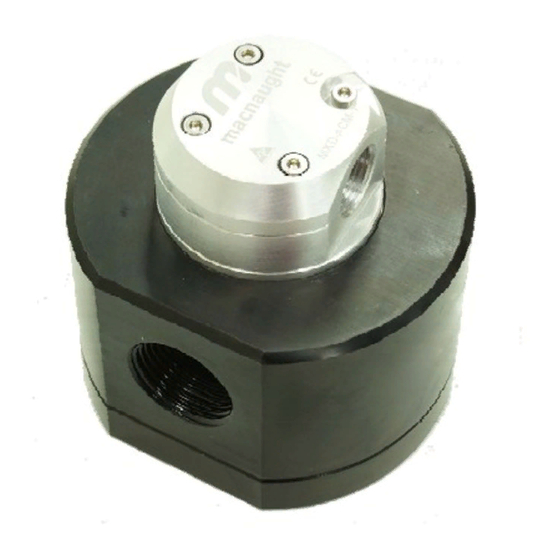
mx flowmeter series
Hide thumbs
Also See for MX Series:
- Manual (32 pages) ,
- Instruction manual (32 pages) ,
- Instruction manual (16 pages)
Table of Contents
Advertisement
Quick Links
MXL-INST-PULSE
Rev 3
04/2016
MX Series Pulser Options
Macnaught MX flowmeter series
T
O THE OWNER
This manual contains connection and operating instructions for a selection of Pulse output options.
Please read and retain this instruction manual to assist you in the operation and maintenance of these products.
In addition Macnaught offer a comprehensive set of online support materials to compliment this instruction
manual. You can access the website by scanning the QR code or visiting the Macnaught website
www.macnaughtflowmeasurement.com.au
INSTRUCTION MANUAL
Page 1 of 20
Advertisement
Table of Contents

Related Manuals for Macnaught MX Series


Summary of Contents for Macnaught MX Series
- Page 1 Please read and retain this instruction manual to assist you in the operation and maintenance of these products. In addition Macnaught offer a comprehensive set of online support materials to compliment this instruction manual. You can access the website by scanning the QR code or visiting the Macnaught website www.macnaughtflowmeasurement.com.au...
-
Page 2: Table Of Contents
NDEX NDEX Installation Page 3 Important Information …………………………………………………………. Page 3 Operating Principle …………………………………………………………. Sensors Page 4 Electrical Specifications …………………………………………………………. DIN Compact Pulser Module Page 5 Introduction …………………………………………………………. Page 6 Overview …………………………………………………………. Page 7 Locking Facility …………………………………………………………. Page 8 Wiring Instructions …………………………………………………………. -
Page 3: Important Information
MPORTANT NFORMATION Reed Switch It is recommended the Reed Switch is used with low supply voltage applications up to 12VDC The reed switch can cause inaccurate rate counts when used with high speed counters. It is advised that a low speed counter is used or alternatively a de-bounce circuit be installed. NPN Open Collector Hall Effect Sensor Suitable for supply voltage applications exceeding 12VDC The output for the hall effect sensor is NPN (current sinking, open collector). -
Page 4: Sensors
LECTRICAL PECIFICATIONS The range of Macnaught Pulser Options is a series of engineered sensor housings, designed to offer the installer flexibility according to the specific application and industrial environment. Each of these variations support a standard set of sensor configurations;... -
Page 5: Introduction
DIN C OMPACT ULSER ODULE NTRODUCTION The DIN Compact Pulser Module offers a variety of sensor and cabling options. Incorporating the M-LOCK (¼ turn) mounting system, the module also provides a locking facility for added security against unauthorised removal. The following provides an overview of both the Sensor and Connection options available with the DIN Pulser Module. -
Page 6: Din Compact Pulser Module
DIN C OMPACT ULSER ODULE VERVIEW Part number: MXD-HH Hall Effect 1 Hall Effect 2 Temperature Part number: MXD-RH Hall Effect 1 Reed Field Connector Part number: MXD-CF Sensor Cable (1.5 meters) Part number: MXD-C1.5 Sensor Cable (5 meters) Part number: MXD-C5 Sensor Cable (10 meters) Part number: MXD-C10 Page 6 of 20... -
Page 7: Locking Facility
DIN C OMPACT ULSER ODULE OCKING ACILITY Locking Facility The DIN Pulse Module has the facility to lock into place after the module has been fitted to the Flowmeter (please see instruction below). The locking facility is to provide an added safeguard against the unauthorised removal of the Pulser Module. *This is enabled by fitting the special ‘Locking screw’... -
Page 8: Wiring Instructions
MXD-RH) IRING NSTRUCTIONS ODULE UMBER Pin designation M12 male connector Contact designation M12 cable Contact designation M12 field connector Page 8 of 20... -
Page 9: Wiring Instructions
MXD-HH) IRING NSTRUCTIONS ODULE UMBER Pin designation M12 male connector Schematic diagram Contact designation M12 cable Schematic diagram Contact designation M12 field connector Schematic diagram Page 9 of 20... -
Page 10: Sensor Cable
DIN C OMPACT ULSER ODULE ENSOR ABLE General Connector M12 (right angle) Standards / regulations IEC 61076-2-101 Part Numbers MXD-C1.5 1.5 meter connection cable MXD-C1.5 5 meter connection cable MXD-C1.5 10 meter connection cable Technical Specifications (Plug and socket) Number of positions Protection IP67 Material of body... -
Page 11: Field Connector
DIN C OMPACT ULSER ODULE IELD ONNECTOR Connector General Connector Standards / regulations IEC 61076-2-101 Technical Specifications Number of positions Protection IP67 Connection method screw connection Conductor cross section 0.25mm² - 0.75mm² Material of body Material of knurled section nickel plated brass Sealing material NBR (nitrile rubber) Ambient temperature... -
Page 12: Introduction
NDUSTRIAL ULSE NTRODUCTION The Industrial Pulse Cap comprises of 3 major components. (See ‘exploded diagram’ on page 13) 1. INDUSTRIAL PULSER CAP 2. PCB (sensor board) 3. SECURE BASE PLATE In order to access the PCB, or for the removal/replacement of the complete Pulser Module, the following procedure applies. -
Page 13: Industrial Pulse Cap
NDUSTRIAL ULSE XPLODED DIAGRAM Pulser Cap Screws Pulser Cap Pulser Cap Gasket PCB screws Circlip Base Plate Flowmeter Page 13 of 20... -
Page 14: Technical Specifications
NDUSTRIAL ULSE PECIFICATIONS Technical Specifications Construction Aluminium Protection IP67 Ambient Temperature (operation) -25°C - 120° Cable Gland Entry ½” NPT or M20x1.5 Part Numbers MXD-ACM-1 sensor Reed-Hall / gland entry M20x1.5 MXD-ACM-2 sensor Dual Hall / gland entry M20x1.5 MXD-ACN-1 sensor Reed-Hall / gland entry ½”... -
Page 15: Pcb Terminal Block Specifications
PCB T NDUSTRIAL ULSE ERMINAL BLOCK TERMINAL BLOCK BASE PLATE Page 15 of 20... - Page 16 PCB T NDUSTRIAL ULSE ERMINAL BLOCK PCB Terminal Block Connection Method Push in spring connection Number of positions Nominal cross section 0.5mm Stripping length Connection Data Conductor cross section solid (min) 0.14mm Conductor cross section solid (max) 0.5mm Conductor cross section flexible (min) 0.2mm Conductor cross section flexible (max) 0.5mm...
-
Page 17: Wiring Diagrams
NDUSTRIAL ULSE IRING DIAGRAMS Reed / Hall Effect configuration Dual Hall Effect configuration Page 17 of 20... - Page 18 OTES Page 18 of 20...
- Page 19 The WEEE Directive requires the recycling of waste electrical and electronic equip- ment in the European Union. Whilst the WEEE Directive does not apply to some of Macnaught’s products, we sup- port its policy and ask you to be aware of how to dispose of this product.
- Page 20 Page 20 of 20...
Need help?
Do you have a question about the MX Series and is the answer not in the manual?
Questions and answers