vimec V65 B.I. Original Instructions Manual
Hide thumbs
Also See for V65 B.I.:
- Manual (19 pages) ,
- Use and maintenance (73 pages) ,
- Original instructions manual (86 pages)
Table of Contents
Advertisement
USE AND MAINTENANCE
ASSEMBLY INSTRUCTIONS
SPARE PARTS MANUAL
DATE __________ APPROVED ____________
VIMEC reserves the right to make any modification and change to its products at any time in compliance with the technical developments.
STAIRLIFT
V 65 ELECTRONIC
MODEL
B.I. - INDEPENDENT BARS
B.R. - RETRACTABLE BARS
MANUAL CODE
7512132
30 - 10 - 2014
Original instructions
Vimec s.r.l
Via Parri, 7 - 42045 Luzzara - Reggio Emilia- Italy
Tel. + 39 0522 970 666 - Fax. + 39 0522 970919
www.vimec.biz
Page 03 - 17
Page 18 - 42
Page 43 - 87
Advertisement
Chapters
Table of Contents

Related Manuals for vimec V65 B.I.


Summary of Contents for vimec V65 B.I.
- Page 1 SPARE PARTS MANUAL Page 43 - 87 MANUAL CODE 7512132 30 - 10 - 2014 DATE __________ APPROVED ____________ VIMEC reserves the right to make any modification and change to its products at any time in compliance with the technical developments.
- Page 2 VIMEC S.r.l. “Original” Declaration of Conformity _________________________________________________________ “EC” DECLARATION OF CONFORMITY The manufacturer: Via Parri n.7 , 42045 Luzzara (R.E.) ITALIA Tel. 0522/970666 r.a. Fax 0522/970919 (Name and address of the person authorised to compile the technical file: Name: Marco Marchetti Address: Via Parri n.7, 42045 Luzzara (R.E.) ITALY - Tel.
-
Page 3: Table Of Contents
USE AND MAINTENANCE CONTENTS OF THE MANUAL 1. Stairlift and manufacturer identification data Page 2. After-sales service Page 3. Description of the stairlift Page 4. Technical specifications Page 5. Intended and improper uses of the stairlift Page 6. Preparation for commissioning Page 7. -
Page 4: Stairlift And Manufacturer Identification Data
1) STAIRLIFT AND MANUFACTURER IDENTIFICATION DATA I - 42045 Luzzara (RE) Via Parri,7 - Tel. + 039 0522 970 666 TYPE SERIAL Nr. (Nr) - - - - YEAR OF MANUFACTURE - - - - WORKING LOAD (Kg) - - - POWER (V / A / Hz) 230 / 5 / 50... -
Page 5: Description Of The Stairlift
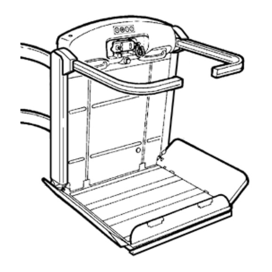
3) DESCRIPTION OF THE STAIRLIFT FIG.1 3.1) Description Lift unit - Fig. 1 Comprises: - carriage - load-bearing structure - safety bars - Fig. 1/a. - load platform - Fig. 1/c. - casing - Fig. 1/b. - control board - Fig. 1/d. Contains: The control board carries the following controls: - control enabling key with start button - Fig. - Page 6 - transmission components - Fig. 3/b (units with gradient FIG.3 bis < 20°). - electric system - Fig. 3/c. As an optional, the stairlift can be also provided complete with double drive chain (Fig. 3 bis) and chain microswitch (Fig. 3 bis). Rails - Fig.
- Page 7 - Set of bars - Fig. 7/f. FIG.6 bis - Platform - Fig. 7/c. - Casing - Fig. 7/d. - Handwheel for manual operation - Fig. 7/e. The system must be installed by skilled ope- rators authorised by VIMEC. FIG.7...
-
Page 8: Technical Specifications
3.6) Reference technical standards The stairlift complies with the following norms: - Directive 2004/108/EEC “Electromagnetic Compatibility” - Directive 2006/95/EEC “Low Voltage” - Directive 2006/42/EEC “Machinery Directive” 4) TECHNICAL SPECIFICATIONS - Drive system Worm gear reduction unit Ratio 1/40 - Performance levels Travel direction Forward/backward Speed (up/down) -
Page 9: Intended And Improper Uses Of The Stairlift
5) INTENDED AND IMPROPER USES OF THE STAIRLIFT 5.1) Intended uses The stairlift is a system for transporting one person SEATED ON A WHEELCHAIR OR ON A SPECIAL SEAT (optional), suitable for installation on staircases having the following characteristics: - Location: Indoor and outdoor - Steps: Parallel... -
Page 10: Correct Use Of The Stairlif
7) CORRECT USE OF THE STAIRLIFT IN INDEPEN- FIG.8 DENT BAR AND RETRACTABLE BAR VERSIONS WARNING: BEFORE USING THE STAIRLIFT, READ THIS MANUAL CAREFULLY. The stairlift must only be used in accordance with the intended uses described in section 5. 7.1) Starting position The stairlift is parked at one end of the staircase with the platform folded up (Fig. - Page 11 5) The stairlift stops at the destination floor; release the FIG.11 up button and press it again, the bars and the guard facing in the up direction automatically move to the drive-off position. The guard and the bar facing in the down direction are now locked in the safety position, to ensure safety during drive-off and upon new drive-on.
- Page 12 7.3) Stairlift operated by attendant. FIG.13 If the person using the stairlift is not self-sufficient, it must be operated by an attendant, using the remote control board (Fig. 13) or the control board with spiral UP/DOWN BUTTONS cable (Fig. 14), depending on the customer’s request. The attendant must follow the stairlift from behind with respect to the moving direction.
-
Page 13: Safety Systems
When tripped, this device stops the stairlift. ATTENZIONE: in this case the stairlift remains locked out of use and an authorised VIMEC techni- cian must be called in to put it back into service. b) Bars and guard boards During use the platform (Fig. - Page 14 - Fig. 19/b WARNING: In this case the stairlift remains locked out of use and an authorised VIMEC tech- FIG.20 nician must be called in to put it back into service.
-
Page 15: Maintenance
STOP button is working properly. If the STOP Six-monthly checks: button does not halt stairlift movements, DO NOT USE the stairlift! Call in an authorised VIMEC tech- a) Safety devices nician immediately. Check that on contact with an obstacle, the anti-impact... - Page 16 f) Stability of the rail Check all the fixing screws of the connections to the mounts and any expansion plugs present. g) General checks Check all moving parts, the guards, labels and signs. Check the batteries and the warning lights of the power supply unit.
-
Page 17: Wiring Diagrams
45°. Differential circuit breaker trip- Press the reset button. If it does ped. not remain in the ON position, call in an authorised VIMEC technician. No power supply. Check the power supply; see point 7.6 (operating by hand). A safety device has been tripped. - Page 18 ASSEMBLY INSTRUCTIONS CONTENTS OF THE MANUAL 1. System supply condition Page 19 2. Installing the lower rail Page 20 3. Installing the upper rail Page 22 4. Assembling the carriage Page 23 5. Positioning the charging station (if applicable) Page 25 6.
-
Page 19: System Supply Condition
WARNING: Remove the bar assemblies (Fig. 1/c) 1) SYSTEM SUPPLY CONDITION before fitting the carriages onto the rails. The stairlift is supplied subdivided into the following components: Casings and on-board control panel (Fig. 1/d). Lift structure (Fig. 1/a) WARNING: Remove the upper and lower casings Complete with gear motor, drive components with safety (Fig. -
Page 20: Installing The Lower Rail
2) INSTALLING THE LOWER RAIL FIG.5 - Use the assembly markings (Fig. 3/b) to identify the first section of rail, with the bend (Fig. 3/a) starting from the top floor. N.B.: If there are no bends, find the first straight section (Fig. - Page 21 10/a), it is advisable the use of special test feet (Fig. on which the brushes operate is clean, and remove 10/b) (contact Vimec’s assistance since they are any dirt if necessary. excluded from the supply) to be plugged into the rail WARNING: The rail fixing screws (Fig.
-
Page 22: Installing The Upper Rail
3) INSTALLING THE UPPER RAIL - Place the spacers (Fig. 11/a) (order them from the Vimec service department since they are not included in the supply package) at each end of the first section of rail installed (Fig. 11/b) (bend) and lock them firmly in position by turning the lever as shown (Fig. -
Page 23: Assembling The Carriage
4) INSTALLING THE CARRIAGE FIG.15 - Place the main structure, complete with carriages, in the parking area at the bottom floor. - Screw the M10x30 screw (Fig. 15/a) with washer (Fig. 15/b) onto the clutch plate assembly (if installed) in order to release the upper carriage from the clutch assembly. - Page 24 the rail (Fig. 19/e), firmly tighten the screws (Fig. 19/a - Make the joint in the busbar (Fig. 17/d) as described and 19/f). earlier. - Fit the upper rail (Fig. 18/a) into the tilting device (Fig. - Version without busbar 18/b) and use the upper handwheel (Fig.
-
Page 25: Positioning The Charging Station (If Applicable)
- Insert the charging shoes in the contact profile so When assembly of the rail is complete, for stairlifts that the negative pole (black wire) is ALWAYS to the with constant gradient of less than 20°, check the left, and the positive pole (red wire) is to the right gradient of the entire rail (maximum permitted error (Fig. - Page 26 - Move the stairlift to a position where it does not get FIG.23 in the way of the assembly procedure, then pass the cables from the power supply unit through the hole shown Fig. 23/a (female connection) and connect them to their respective contacts (male connection) respec- ting the polarity.
-
Page 27: Connecting The Power Supply Unit
6) CONNECTING THE POWER SUPPLY UNIT WARNING: all safety devices are deactiva- - Connect the cables (positive and negative) to the ted (the operator is responsible for ensuring safety). busbar terminal provided, fixed to the rail (Fig. 27/a- Fig. 27/b). - If the charge station is installed, connect the cables FIG.27 leading from the station direction to the power supply... - Page 28 - Use the UP and DOWN controls on the control panel (Fig. 29/a) to bring the structure, complete with carria- ge, to the chosen floor, in order to continue assembly operations in complete safety. - Reassemble the casing (Fig. 29/b). - Fit the spacing gauge (Fig.
-
Page 29: Fixing The Connecting Feet
N.B.: Move the stairlift up to the 1st rigid connection and FIG.32 if it is not horizontal, screw down the M10x30 screw (Fig. 15/a) with washer (Fig. 15/b) onto the clutch assembly to release the upper tilting device from the clutch assembly. -
Page 30: Fitting The Bars
9) FITTING THE BARS 9.1) Independent bars Fit the bar supports (Fig. 36/b) on the stairlift frame (Fig. In the bottom of the bar, connect the wire (Fig. 36/e) to 36/a), aligning the locator pins provided (Fig. 36/c). the platform interlock system (Fig. 36/f). Fix the bars with the screws supplied (Fig. -
Page 31: Assembling The Platform With Driven Front Access
7) ASSEMBLING THE PLATFORM WITH DRIVEN the relative screws. FRONT ACCESS (B.I. - B.R.) b) Make sure that the two platform supports, fixed by a On customer request it is possible to have a platform wedge and a plastic clamp, are in the assembly position with overturning front side (Fig. - Page 32 - Insert the eccentric (Fig. 41/f) with front guard board 41/f) using the screw, nut and lock-nut, leaving the ne- handling belt (Fig. 41/g) on the special pin (Fig. 41/d) cessary clearance to allow the rotation of the eye itself. and fix it with a snap ring (Fig.
- Page 33 B.R.: Fix the cable (Fig. 42/a) already fitted to the bars adjustment from the platform supports. on the side bar guard board with the screws provided. (i) Tighten the nut and lock-nut with a driving torque of - Fix the cable eye (Fig. 42/b) to the eccentric (Fig. 42/c) 4 daN ±...
-
Page 34: Assembling The Platform
11) ASSEMBLING THE PLATFORM c) Fit the platform, keeping it vertical and turning it through 90° as shown (Fig. 47). a) Remove the top plate from the platform by undoing the screws provided. d) Fix the platform to the frame using the TSPCE M8 flat head screws provided (Fig. - Page 35 other platforms upon customer’s request, are equipped f) Connect the wires (Fig. 49/c) to the side guard boards, passing them around the pin (Fig. 49/a). with a clinometer to check any footboard overloads If the guards are not opened or closed correctly, adjust (Fig.
-
Page 36: Preparing The Stairlift For Setup
be fully open in work mode. FIG.55 To remove any possible clearances, a load of around 75-100 kg must be applied to the platform (it is sufficient that an installer gets onto the footboard to remove such clearance). Now, reset the clinometer by making a jumper on the rear of the card (Fig. -
Page 37: Setting Up The Stairlift
28/d). is tripped. If necessary, replace the whole brake unit. The display lights up, and the name “VIMEC V65” appears: c) Drive mechanics Check that the teeth of the drive sprockets and the - Press "enter". -
Page 38: Adjusting Rail Bend Rollers
15) ADJUSTING THE BEND ROLLERS FIG.57 Working on the bend with the lowest gradient (Fig. 56/a) set the bend rollers in contact with the rail (Fig. 56/b). After adjustment, tighten the roller fixing screws (Fig. 56/c) to a torque of 2 daNm. This adjustment will be maintained for the other bends. -
Page 39: Fitting The Over-Run Device Cams
17) FITTING THE OVER-RUN DEVICE CAMS - Fix the cam (Fig. 58/e - 59/e), on the rail 50 mm from the stairlift’s centre-line marked earlier. - Set the stairlift in the stop position (Fig. 58/a - 59/a) and mark the position of the stairlift’s centre-line on the - Tighten all screws when done. -
Page 40: Check The Position Of The Over-Run Device Cam And Plates
18) CHECKING THE POSITION OF THE OVER-RUN FIG.60 UPPER DEVICE CAM AND PLATES FLOOR Before final testing of the stairlift, check that the limit stop (Fig. 60/a-61/a) is correctly positioned. This position is correct if the dimensions are as shown in the drawings in Fig. -
Page 41: Fitting The Casings
- Check on fixing of the rail FIG.65 - Check that the rail is positioned in accordance with the dimensions stated in the installation drawing (or system layout) supplied with the stairlift. - Check that all the fixing screws of the connections to the mounts or any expansion plugs are stable and firmly tightened. -
Page 42: Fitting The Caps And End Covers
22) FITTING CAPS AND END COVERS FIG.68 - Press the caps (Fig. 68/a) supplied onto each rail connection. - Fit the connecting strips (Fig. 69/a) onto the top and bottom ends of the rails. To do this, simply fit the end caps (Fig. - Page 43 PARTS CATALOGUE CATALOGUE INDEX 1. Top carriage Page 44 2. Bottom carriage Page 47 3. Frame Page 50 4. Platform Page 58 Page 62 5. Safety bars Page 66 6. Retractable safety bars Page 69 7. Guards Page 72 8. Connectors Page 75 9.
- Page 50 FRAME...
- Page 54 FRAME EN 81 40...
- Page 69 RETRACTABLE SAFETY BARS...
- Page 72 GUARDS...
- Page 75 CONNECTORS...
- Page 80 CONTROL CIRCUIT BOARD...
- Page 82 RETRACTABLE BARS CONNECTED BARS INDEPENDENT BARS PLATFORM/GUARD BOARD DRIVE CABLES...
- Page 84 V65 RAIL JOINTS...
- Page 86 CONTROL BOARDS...
Need help?
Do you have a question about the V65 B.I. and is the answer not in the manual?
Questions and answers