Table of Contents
Advertisement
ASSEMBLY ISTRUCTIONS
SPARE PARTS MANUAL
DATE ____________ APPROVED ____________
VIMEC reserves the right to make modifications and changes to its products at any time in response to technological developments.
STAIRLIFT
V 64 - 74
MODEL
B.I. - INDEPENDENT BARS
B.C. - CONNECTED BARS
B.R. - RETRACTILE BARS
MANUAL CODE
7 5 1 2 0 2 6 / g
04 - 11 - 2004
Page 03 - 14
Page 15 - 25
Page 26 - 44
Advertisement
Table of Contents

Related Manuals for vimec V64 B.I.


Summary of Contents for vimec V64 B.I.
- Page 1 MANUAL CODE 7 5 1 2 0 2 6 / g DATE ____________ APPROVED ____________ 04 - 11 - 2004 VIMEC reserves the right to make modifications and changes to its products at any time in response to technological developments.
- Page 3 7502026 USE AND MAINTENANCE CONTENTS OF THE MANUAL 7. CORRECT USE OF THE STAIRLIFT 9. MAINTENANCE TO ENSURE SAFE OPERATION CAUTION This symbol accompanies a number of essential safety instructions. Compliance with these instructions does not release users from their obligation to follow all additional safety regulations.
- Page 4 7502026 1) STAIRLIFT AND MANUFACTURER IDENTIFICATION DATA LOAD - - - kg SERIAL Nr. SERIAL Nr. _ _ _ _ _ _ _ _ 2) AFTER-SALES SERVICE DEALER’S RUBBER STAMP, INDICATING CONTACT FOR AUTHORISED AFTER - SALES SERVICE...
- Page 5 7502026 FIG.2 3) DESCRIPTION OF THE STAIRLIFT 3.1) Description Lift unit FIG.3 - connection for handwheel for manual operation Fig.2/f. Rails FIG.1 FIG.4...
- Page 6 3.4) Warning and compulsory procedure signs and data-plates The stairlift is fitted with the following warning and compulsory procedure signs and data-plates: 3.5) Supply condition The system must be installed by specialist operators authorised by VIMEC. FIG.7...
- Page 7 7502026 3.6) Reference technical norms 4) TECHNICAL SPECIFICATIONS - Drive system - Performance levels V64/74 - Duty cycles - Ambient conditions - Electric system - Controls...
- Page 8 7502026 5) INTENDED AND IMPROPER USES OF THE STAIRLIFT 5.1) Intended use V64/74 SEATED ON A WHEELCHAIR OR ON A SPECIAL SEAT (optional) STRAIGHT CONSTANT - Ambient: Indoor and outdoor - Steps: Parallel - Gradient: Minimum 0° - Maximum 50° User characteristics: Self-sufficient, physically and mentally suitable, familiar with the equipment’s operation and the use and maintenance instructions.
- Page 9 7502026 6.2) Electrical connection - B.C. Version both contained in a box with padlock fitting - B.R. - B.I. Version CAUTION: The box with padlock fitting containing the master switch must be installed close to the lift.There must be no obstacles to access to this box.
- Page 10 7502026 FIG.11 5) B.C. Version. 5) B.R. - B.I. Version. FIG.12 N.B.: CAUTION: Pressing two buttons simulta- neously, whether on the board on the lift or the board at the floor, is strictly prohibited. CAUTION: The person transported must al- ways remain in the recommended position, with the wheelchair brakes on, if the wheelchair is electric, turn it off, as long as transport is in progress.
- Page 11 7502026 FIG.13 CAUTION: B.R. - B.I. Version N.B.: 7.3) Lift operated by attendant. FIG.14 7.4) Stairlift stopped at the other end of the stair- case (optional call - send function). CAUTION: Never send/call the lift to a floor unless the WHOLE travel route can be seen. 7.5) Manual operation in emergency FIG.15 Skill level OC: Trained operator with specific skills...
- Page 12 7502026 CM_2912 16/11/05 FIG.13 CAUTION: In the B.R. - B.I. Version, the plat- form can only be operated with the down side bar in the working position. N.B.: If the platform fold button is accidentally pressed when someone is on the lift, a motor overload cut-out is tripped, stopping the electromechanical actuator.
- Page 13 EMERGENCY CAUTION: In case of a system failure or trip- ping of the safety gear, call in an authorised VIMEC technician. In case of any kind of malfunction, put the lift out of use by turning the master switch to OFF.
- Page 14 CAUTION: The recommended maintenance frequencies must be complied with. CAUTION: in this case the lift remains locked out of use and an authorised VIMEC technician must 9.1) Parts requiring regular inspection be called in to put it back into service.
- Page 15 7502026 f) General checks b) Control panels at the floors g) Guide cleaning c) Electrical system Annual checks: a) Controls 9.2) Problem - Possible causes - Possible remedies Skill level: O - Trained operator Problem Possible causes Possible remedies 10) ELECTRICAL SYSTEM DIAGRAMS 12) INFORMATION ON DISPOSING OF PARTS OF THE LIFT AND THE SUBSTANCES IT CONTAINS a) Disposing of rubber and plastics...
- Page 16 7602026 ASSEMBLY INSTRUCTIONS CONTENTS OF THE MANUAL 1. System supply condition Page 16 2. Positioning the rail Page 17 3. Assembling the carriage Page 19 4. Complete actuator assembly Page 19 5. Assembling the bodywork Page 19 6. Assembling the platform with motorized access frontal Page 21 7.
- Page 17 7602026 FIG.1 1) SYSTEM SUPPLY CONDITION The stairlift is supplied subdivided into the following components: Lift structure (Fig. 1/a) Complete with gear motor, safety bars, drive components and electrical system. Carrier platform (Fig. 1/b) Complete with guard boards and sensor base with safety microswitches.
- Page 18 7602026 FIG.5 2) INSTALLING THE RAIL ONLY FOR STOCK GUIDE: - Following the dimensions shown on the assembly drawing (see example in Fig. 5) specific to each installation, place the rail in position of the guide connections using the screws M8 x 25 (Fig.
- Page 19 7602026 ONLY FOR STOCK GUIDE: - Holding to the specific dimensions (Fig. 9) for each equipment, proceed to the drilling of the chain holder profile (aluminium bonnet - Fig. 10). - Assemble the terminal mesh (Fig. 11/a) to the cable carriage chain (Fig. 11/b) and fix it to the support. The cable (Fig.
- Page 20 7602026 FIG.12 ONLY FOR STOCK GUIDE: - Pass the power supply cable inside the spiral tube and fix with the proper fairlead to the lid by the top side of the guide (after having removed the feather of the down side of the lid) (Fig.9/e). - Drill with Ø...
- Page 21 7602026 FIG.17 - Fix the down limit stop plate (SQ16 or SQ12) (Fig. 12/g). - Fix the up limit stop plate (SQ16 or SQ12) and the up overlimits microswitch (SQ4) (Fig. 12/h). - Connect the safety gear microswitch connector (SQ2) - Fig.
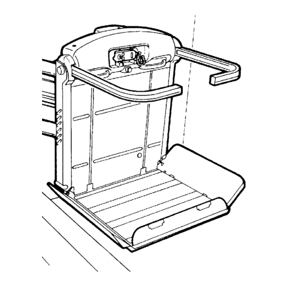
- Page 22 7602026 FIG.21 ASSEMBLING PLATFORM WITH MOTORIZED ACCESS FRONTAL (B.I. - B.C. - B.R.) On customer request it is possible to have a footboard with overturning front side (Fig. 20/a). Such a footboard permits, on the lower floor only, to access/go down perpendicularly to the machine. 6.1) Assembling the platform a) Remove the top plate from the platform by undoing the relative screws.
- Page 23 7602026 B.R.: fix the cable (Fig. 24/f) already present on the f) Connect the lateral guard board operating cables side bar chute with special screws. (Fig. 24/f) and frontal (Fig. 24/e) to the fork (Fig. 24/b). - Tighten with nut and screw. - Fix the cable eye (Fig.
- Page 24 7602026 FIG.27 7) ASSEMBLING THE PLATFORM a) Remove the top plate from the platform by undoing the relative screws. b) Make sure that the two platform supports, fixed by a wedge and a plastic clamp, are in the assembly position (Fig.
- Page 25 7602026 FIG.30 8) CONNECTING THE ELECTRICAL SYSTEM Two wires lead out from the top end of the extruded aluminium raceway on the rail (Fig. 31/a/b) - blue wire 4x1, power supply - green wire 8x0,35 for control board at floor (optional) Connect these wires as follows: - Connect the 4x1 blue wire (Fig.
- Page 26 7602026 FIG.33 11) FINAL TESTING Supply power to the system and perform the SN CARRIAGE CONFIGURATION following functional checks: FRONT VIEW - Load test: - Load the lift with 1.1 times the rated load stated on the nameplate. - Send the lift up and down several times, checking its stability on the rail.
- Page 27 7201026 CATALOGO RICAMBI - PARTS CATALOGUE ERSATZTEILKATALOG - CATÁLOGO DE REPUESTOS CATALOGUE DES PIECES DE RECHANGE INDICE DEL CATALOGO CATALOGUE INDEX - INHALTSVERZEICHNIS ÍNDICE DEL CATÁLOGO - INDEX 6. Protezioni Pag. 39 N° 7801110 1. Carrello Pag. 27 N° 7801104 Carriage Guards Schutzeinrichtungen...
- Page 30 TELAIO 7801105...
- Page 37 BARRE DI SICUREZZA 7801190 RETRATTILI...
- Page 40 SOLO PER MOD. V64 SOLO PER MOD. V74 PROTEZIONI 7801110...
- Page 48 BARRE RETRATTILI BARRE COLLEGATE BARRE INDIPENDENTI CAVI AZIONAMENTO PEDANA/BANDELLA 7804457...
Need help?
Do you have a question about the V64 B.I. and is the answer not in the manual?
Questions and answers