Table of Contents
Advertisement
USE AND MAINTENANCE
ASSEMBLY INSTRUCTIONS
SPARE PARTS MANUAL
DATE ____________ APPROVED ____________
VIMEC reserves the right to make modifications and changes to its products at any time in response to technological deve-
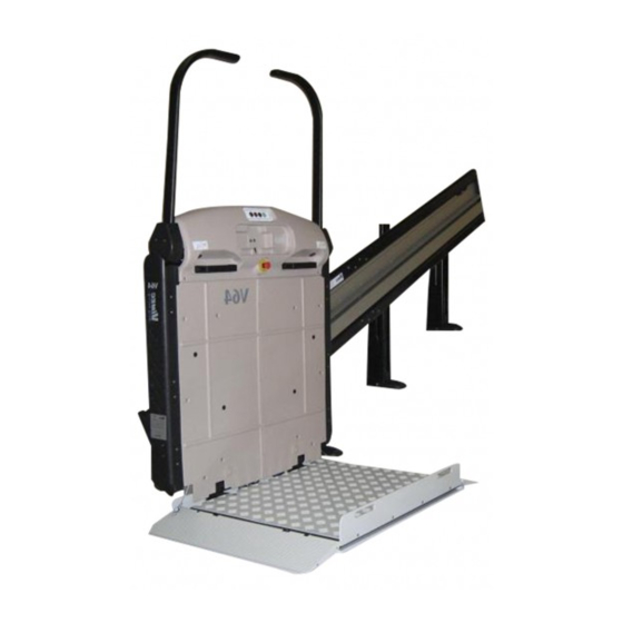
STAIRLIFT
V 64 - 74
MODEL
B.I. - INDEPENDENT BARS
B.R. - RETRACTABLE BARS
MANUAL CODE
7512131
01 - 12 - 2009
lopments.
Original instructions
Vimec s.r.l
Via Parri, 7 - 42045 Luzzara - Reggio Emilia- Italy
Tel. + 39 0522 970 666 - Fax. + 39 0522 970919
www.vimec.biz
Page 03 - 15
Page 16 - 28
Page 29 - 59
Advertisement
Table of Contents

Related Manuals for vimec V 64


Summary of Contents for vimec V 64
- Page 1 SPARE PARTS MANUAL Page 29 - 59 MANUAL CODE 7512131 01 - 12 - 2009 DATE ____________ APPROVED ____________ VIMEC reserves the right to make modifications and changes to its products at any time in response to technological deve- lopments.
- Page 2 7512131 7512116 7511131 _________________________________________________________ “EC” DECLARATION OF CONFORMITY The manufacturer: Via Parri n.7 , 42045 Luzzara (R.E.) ITALIA Tel. 0522/970666 r.a. Fax 0522/970919 (Name and address of the person authorised to compile the technical file: Name: Marco Marchetti Address: Via Parri n.7 , 42045 Luzzara (R.E.) ITALY - Tel. +39/0522/970666) states on his own responsibility that the stair lift for users on a wheelchair type: –...
- Page 3 7512131 7512116 7511131 USE AND MAINTENANCE CONTENTS OF THE MANUAL 1. Stairlift and manufacturer identification data Page 04 2. After-sales service Page 04 3. Description of the stairlift Page 05 4. Technical specifications Page 07 5. Intended and improper uses of the lift Page 08 6.
- Page 4 7512131 7512116 7511131 1) STAIRLIFT AND MANUFACTURER IDENTIFICATION DATA I - 42045 Luzzara (RE) Via Parri,7 - Tel. + 039 0522 970 666 TYPE SERIAL Nr. (Nr) - - - - YEAR - - - - LOAD (Kg) - - - POWER (V / A / Hz) 230 / 5 / 50...
- Page 5 7512131 7511131 3) DESCRIPTION OF THE STAIRLIFT FIG.2 3.1) Description Lift unit - Fig. 1 Comprises: - carriage - load-bearing structure - safety bars - Fig. 1/a. - load platform - Fig. 1/c. - casing - Fig. 1/b. - control board - Fig. 1/d. Contains: - motor - Fig.
- Page 6 - Rails and rail connections - Fig. 7/a. FIG.6 - Carriage - Fig. 6. - Lift structure. - Platform - Fig. 7/c. - Casing - Fig. 7/d. - Handwheel for manual operation - Fig. 7/e. The system must be installed by specialist operators authorised by VIMEC. FIG.7...
- Page 7 7512131 7511131 3.6) Reference technical norms The stairlift complies with the following norms: - Directive 2004/108/CEE “Electromagnetic Compa- tibility” - Directive 2006/95/CEE “Low Voltage” - Directive 2006/42/CEE “Machinery Directive” 4) ) TECHNICAL SPECIFICATIONS - Drive system Irreversible worm gear Ratio 1/80 - Performance levels Travel direction Forward/back...
- Page 8 7512131 7511131 5) INTENDED AND IMPROPER USES OF THE ST AIRLIFT 5.1) Intended uses The Mod. V64/74 stairlift is a system for transporting one person SEATED ON A WHEELCHAIR OR ON A SPECIAL SEAT (optional) with STRAIGHT rail at CONSTANT gradient which can be installed on stairs having the following characteristics: - Ambient: Indoor and outdoor...
- Page 9 7512131 7511131 - If the stairlift is at the lower floor, bring the down - side bar into the rest position to allow the wheelchair 6.2) Electrical connection to move onto the platform. The power supply lead is of 4x1 mm2 type (number of 1) For stairlifts with motor-operated platform (op- wires per gauge).
- Page 10 7512131 7511131 4) Press the up button (Fig. 9/c); the guards and bars FIG.11 automatically move to the safety position and the stai- rlift sets off. 5) B.R. - B.I. Version. At the destination floor, the stairlift stops; if the up button is kept pressed, the bars and the guard facing in the up direction automatically move to the drive-off position.
- Page 11 7512131 7511131 (Fig.9/d) is accidentally pressed when someone is on FIG.13 the stairlift, a motor surge protector is tripped, stopping the electromechanical actuator. UP/DOWN BUTTONS 7.3) Stairlift operated by attendant. If the person who uses the system is not self-sufficient, the stairlift can be operated by an attendant, using the special control board - Fig.
- Page 12 7511131 FIG.16 WARNING: In case of a system failure or trip- ping of the safety gear, call in an authorised VIMEC technician. In case of any kind of malfunction, put the stairlift out of use by turning the master switch to OFF.
- Page 13 7512131 7511131 WARNING: in this case the stairlift remains locked out of use and an authorised VIMEC tech- nician must be called in to put it back into service. b) Power supply The stairlift is supplied at 230 V A.C. single-phase, while the auxiliary circuit is supplied at 24 V D.C.
- Page 14 7512131 7511131 9) MAINTENANCE WARNING: Keep well away from all unpro- VIMEC products are built in compliance with the tected moving parts. current Machinery Directive, that emphasizes the - Restore the power supply and press the down button importance of safety both in designing and building until the hook engages.
- Page 15 ON position, call in an authorised VIMEC technician. Check the power supply; see point 7.5 No power supply. (operating by hand). Call in an authorised VIMEC technician. A safety device has been tripped. Call in an authorised VIMEC technician. Safety gear tripped.
-
Page 16: Table Of Contents
7512131 7511131 ASSEMBLY INSTRUCTIONS CONTENTS OF THE MANUAL 1) System supply condition Page 17 2) Modular rails Page 18 3) Positioning the rail Page 19 4) Assembling the carriage Page 22 5) Complete actuator assembly Page 22 6) Assembling the bodywork Page 22 7) Assembling the platform with driven front access... -
Page 17: System Supply Condition
7512131 7511131 1) SYSTEM SUPPLY CONDITION FIG.1 The stairlift is supplied subdivided into the following components: Lift structure (Fig. 1/a) Complete with gear motor, safety bars, drive compo- nents and electrical system. Carrier platform (Fig. 1/b) Complete with guard boards and sensor base controlled by safety microswitches. -
Page 18: Modular Rails
7512131 7511131 2) MODULAR RAILS 2.3) Type of sheath Four types of sheath are provided: The production of rail modules implies a fixed position - Sheath for rails up to 3300 mm of the connecting plates. In case of wall fixing, no - Sheath for rails between 3301 mm up to 6900 mm additional operation is foreseen. -
Page 19: Positioning The Rail
7512131 7511131 3) INSTALLING THE RAIL FIG.6 MODULAR OR STOCK RAIL: - Following the dimensions shown on the assem- bly drawing (see example in Fig. 5) specific to each installation, place the rail in position of the rail connections using the screws M8 x 25 (Fig. 5/a) (driving torque: 1,6 ÷... - Page 20 This table can be only used with alpha angle higher than 20 degrees. Below 20°, it is necessary to carry out a special study according to the type of staircase. In case of angles lower than 20°, please contact Vimec to receive soon the rail installation data.
- Page 21 7512131 7511131 MODULAR OR STOCK RAIL: - Holding to the specific dimensions (Fig. 9) for each equipment, proceed to the drilling of the chain holder profile (aluminium casing - Fig. 10). - Assemble the terminal link (Fig. 11/a) to the cable holder chain (Fig. 11/b) and fix it to the support. The cable (Fig.
-
Page 22: Assembling The Carriage
7512131 7511131 MODULAR OR STOCK RAIL: FIG.12 - Pass the power supply cable inside the spiral tube and fix with the proper cable gland to the lid by the top side of the rail (after having removed the tab of the down side of the lid) (Fig. 9/e). - Drill with Ø... - Page 23 7512131 7511131 Fix the down limit switch plate (SQ16 or SQ12) (Fig. FIG.17 12/g). - Fix the up limit switch plate (SQ16 or SQ12) and the up over-run microswitch (SQ4) (Fig. 12/h). - Connect the safety gear microswitch connector (SQ2) (Fig.
-
Page 24: Assembling The Platform With Driven Front Access
7512131 7511131 The guide shoe of the chain microswitch must always FIG.21 act on the inner chain as indicated in (Fig. 18bis/i). N.B.: Do not over-stretch the chain. - If necessary, use the handwheel for manual operation to adjust the chain in order to simplify fitting of the chain stretcher - Fig. - Page 25 7512131 7511131 c) Fit the platform, keeping it vertical and turning it - Tighten with nut and screw. through 90° as shown in (Fig. 22). - Insert the eccentric (Fig. 24/h) with handling belt (Fig. d) Fix the platform to the frame using the TSPCE M8 24/g), front guard board on the special pin (Fig.
-
Page 26: Assembling The Platform
7512131 7511131 8) ASSEMBLING THE PLATFORM l) Plug in the connector J4 (Fig. 26 bis). a) Remove the top plate from the platform by undoing the relative screws. FIG.27 b) Make sure that the two platform supports, fixed by a wedge and a plastic clamp, are in the assembly position (Fig. -
Page 27: Connecting The Electrical System
7512131 7511131 CLINOMETER RESET FIG.31 The 1250x800 and 1050x900 standard platforms, and other platforms upon customer’s request, are equipped with a clinometer to check any footboard overloads (Fig. 31/a). Once the platform is completely installed, it must be fully open in work mode. To remove any possible clearances, a load of around 75-100 kg must be applied to the platform (it is sufficient that an installer gets onto the footboard to remove such... -
Page 28: Final Testing
7512131 7511131 12) FINAL TESTING FIG.35 Supply power to the system and perform the fol- lowing functional checks: SN CARRIAGE CONFIGURATION FRONT VIEW - Load test: - Load the stairlift with 1.1 times the rated load stated on the nameplate. - Send the stairlift up and down several times, checking its stability on the rail. - Page 29 7512131 7511131 PARTS CATALOGUE CATALOGUE INDEX 1. Carriage Page 30 2. Frame Page 33 3. Platform Page 36 Page 40 4. Safety bars Page 44 5. Retractable safety bars Page 47 6. Guards Page 50 7. Rail Page 52 8. Electrical panel B.I. Page 54 9.
- Page 33 FRAME...
- Page 50 ONLY FOR MOD. V64 ONLY FOR MOD. V74 GUARDS...
- Page 54 ELECTRICAL PANEL B.I.
- Page 56 COUPLING: CONNECTORS...
- Page 58 RETRACTABLE BARS INDEPENDENT BARS FOOTREST/GUARD BOARD DRIVE CABLES...
- Page 60 CONTROL BOARDS...
Need help?
Do you have a question about the V 64 and is the answer not in the manual?
Questions and answers