
Related Manuals for Rottler SG90MTS


Summary of Contents for Rottler SG90MTS
- Page 1 8029 S 200th Street, Kent, WA 98032 USA | www.rottlermfg.com | Ph: (253) 872-7050 | Fax: (253) 393-0230 Rev 083022...
- Page 2 8029 S 200th Street, Kent, WA 98032 USA | www.rottlermfg.com | Ph: (253) 872-7050 | Fax: (253) 393-0230 Rev 083022...
-
Page 3: Parts Ordering
PARTS ORDERING https://www.rottlermfg.com/documentation.php For optional equipment catalogs, please visit For fastest service ordering parts or equipment, contact us via e-mail with the information below. For customers within the U.S., send emails to parts@rottlermfg.com, for customers outside of the U.S., use intlparts@rottlermfg.com Have the following information on hand to expedite the ordering process: 1. -
Page 4: Manual Sections
MANUAL SECTIONS INTRODUCTION SAFETY CONTROL DEFINITIONS OPERATING INSTRUCTIONS 8029 S 200th Street, Kent, WA 98032 USA | www.rottlermfg.com | Ph: (253) 872-7050 | Fax: (253) 393-0230 Rev 083022... - Page 5 Section 1: Introduction SG90MTS Operations Manual INTRODUCTION Contents Introduction .........................1-1 Description ........................1-2 Disclaimer ........................1-2 Limited Warranty ......................1-3 Online Documentation Access ..................1-4 8029 S 200th Street, Kent, WA 98032 USA | www.rottlermfg.com | Ph: (253) 872-7050 | Fax: (253) 393-0230 Rev 083022...
- Page 6 “Installation Report” located in the Installation Chapter of this manual. We suggest that the new user of the SG90MTS read the CONTROL DEFINITIONS to get an idea how the machine operates. The Operating Instructions chapter should be read in order to familiarize the user with the actual button pushing sequences required to carry out a job.
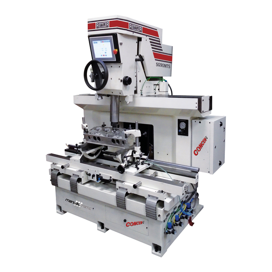
- Page 7 SG90MTS the most versatile machine in the Rottler Seat and Guide machine lineup. The Rottler SG90MTS represents a pinnacle of innovation in modern seat cutting technology. New to this type of machine is the Rottler patented Uni-Pilot tooling technology which allows the operator to move hole-to-hole while cutting seats without the need of re-positioning the pilot or using multiple pilots to process a cylinder head.
- Page 8 Any information regarding final dimensions and finishes that appears in any Rottler literature or that is expressed by anyone representing Rottler is to be regarded as general information to help with the demonstration of or for operator training of Rottler equipment.
- Page 9 SG90MTS Operations Manual Online Documentation Access Online documentation for machines and optional equipment can be accessed at the Rottler website. To access documentation open your browser and navigate to https://www.rottlermfg.com. Scroll to the bottom of the page and under the Owner Resources title click the type of documentation you want to access.
-
Page 10: Table Of Contents
Emergency Procedure ......................2-6 Computer and Controller System Safety ................2-6 Electrical Safety Features Of Rottler DM Controlled Machines ........2-7 8029 S 200th Street, Kent, WA 98032 USA | www.rottlermfg.com | Ph: (253) 872-7050 | Fax: (253) 393-0230 Rev 083022... -
Page 11: Safety Information
Section 2: Safety SG90MTS Operations Manual Safety Information For Your Own Safety Read This Instruction Manual Before Operating This Machine. This is the safety alert symbol. It is used to alert you to potential personal injury hazards. Obey all safety messages that follow this symbol to avoid possible injury or death. - Page 12 DO NOT MODIFY OR ALTER THIS EQUIPMENT in any way. If modifications are deemed necessary, all such requests must be approved and/or handled by Rottler Manufacturing. Unauthorized modifications could cause injury and/or damage to machine and will void the warranty.
-
Page 13: Electrical Power
Section 2: Safety SG90MTS Operations Manual SAFETY DECALS SHOULD NEVER BE REMOVED. They are there to convey important safety information and warn of potential hazards. ALL LOCAL SAFETY CODES AND REGULATIONS should be followed when installing this machine. ONLY QUALIFIED PERSONAL should perform service on the electrical and control systems. -
Page 14: Machine Operator
Section 2: Safety SG90MTS Operations Manual In the event of an electrical short, grounding reduces the risk of electric shock by providing a path of least resistance to disperse electric current. Electrocution or a fire can result if the machine is not grounded correctly. Make sure the ground is connected in accordance with this manual. -
Page 15: Emergency Procedure
Section 2: Safety SG90MTS Operations Manual Machining – Eye protection must be worn during all operations of the machine. Hands must be kept completely away from the cutter head. All chip guards must be in position during machine operations. Work Loading and Unloading – Carefully develop handling methods of loading and unloading work pieces so that no injury can result if hoist equipment or lift connection should fail. -
Page 16: Electrical Safety Features Of Rottler Dm Controlled Machines
Rottler’s direct consent may cause severe injury or death. Electrical Safety Features Of Rottler Controlled Machines All Rottler machines that use the operational control system are designed to comply with all applicable safety standards. This includes but is not limited to the following systems: •... -
Page 17: Left Side Controls
Section 3: Control Definitions SG90MTS Operations Manual CONTROL DEFINITIONS Left Side Controls Section 4 Control Definitions 8029 S 200th Street, Kent, WA 98032 USA | www.rottlermfg.com | Ph: (253) 872-7050 | Fax: (253) 393-0230 Rev 083022... -
Page 18: Right Side Controls
Section 3: Control Definitions SG90MTS Operations Manual Right Side Controls 8029 S 200th Street, Kent, WA 98032 USA | www.rottlermfg.com | Ph: (253) 872-7050 | Fax: (253) 393-0230 Rev 083022... - Page 19 Machining valve seats and Counter Boring ...............4-8 Aligning Spindle to Work ........................4-8 Changing the Spindle Adapters ......................4-8 Fine Feed Engagement ........................4-9 Rottler SG90MTS MANUALMATIC Touch Screen Control Panel ......4-10 Safety Tips Before Machining ................... 4-10 Operation ..........................4-10 Buttons ............................4-11 MANUALMATIC Operation ....................
-
Page 20: Operating Instructions
Insert Sharpener Operation The Rottler sharpening can re-condition inserts to a finish almost identical to new. The grinding wheel is designed to provide a very fine lapped finish across the entire face of the insert. It should be noted that the grinding holder is deigned to accept RCA/RCB inserts on one side and the larger formant RCC inserts on the other. -
Page 21: Built In Venturi Vacuum Tester
Section 4: Operating Instructions SG90MTS Operations Manual Check the insert as you grind it to make sure that it is cleaning up uniformly, also make sure that the set screw does not contact the grinding wheel. When done properly the insert face should look like the image... -
Page 22: Mounting Cylinder Heads
Section 4: Operating Instructions SG90MTS Operations Manual Mounting Cylinder Heads 360 Degree Rollover Fixtures The 360 Degree Rollover fixture is a "clamp-up" design which allows for precise deck height location that results in the ability to achieve equal seat depth when cutting valve seats. The design also allows for easy loading and unloading by rotating the fixture 180 degrees to load the cylinder head deck side down. -
Page 23: Alignment And Setup
Section 4: Operating Instructions SG90MTS Operations Manual Alignment and Setup Alignment and setup applies to both the cylinder head and the machine’s floating head. The goal is to align the centerline of the spindle with the centerline of the valve guide. This is achieved by using Rottlers uni pilot tooling system in conjunction with floating the work head, to position the valve seat cutter directly above the seat and centered on the guide geometry. -
Page 24: Canted Valve Cylinder Heads (Automotive Application)
Section 4: Operating Instructions SG90MTS Operations Manual Canted Valve Cylinder heads (Automotive Application) An optional alignment bar is available that helps establish the front to back alignment on canted valve cylinder heads. The bar is held against two pilots in two adjacent guides. Use the alignment post to adjust the front to back angle of the work head. -
Page 25: Multi-Angle Seat Cutting
Multi angle valve jobs can be completed with ease by utilizing Rottler carbide inserts with desired geometry to create the seat profile. Consult the Rottler Insert Profile Catalog for more information on available seat geometry. Custom seat profiles may also be ordered by request through Rottler manufacturing. -
Page 26: Machining Valve Seats And Counter Boring
Section 4: Operating Instructions SG90MTS Operations Manual Grasp brass frame in middle of gauge and move upward approximately 1/8”. The dial pointer should move as this is done. Center the pointer of the indicator pointing upward and lock the gauge to the pilot using the brass locking screw. -
Page 27: Fine Feed Engagement
Section 4: Operating Instructions SG90MTS Operations Manual Fine Feed Engagement To engage the fine feed mechanism it is necessary to push inward on the spindle handwheel while rotating the fine feed knob until engagement is achieved. To disengage the fine feed simply pull outward on the spindle hand wheel. -
Page 28: Rottler Sg90Mts Manualmatic Touch Screen Control Panel
Section 4: Operating Instructions 4-10 SG90MTS Operations Manual Rottler SG90MTS MANUALMATIC Touch Screen Control Panel Safety Tips Before Machining • Always wear proper Safety Items (such as safety glasses and other personal safety equipment as necessary or required). • Never wear loose fitting clothes or jewelry while working on or around Machine. -
Page 29: Buttons
Section 4: Operating Instructions 4-11 SG90MTS Operations Manual From this screen the operator can choose which mode they would like to machine in. Manual Buttons: BACK - goes 1 page back. VERTICAL ZERO - tap the SET button to set the vertical spindle height. -
Page 30: Changing Language
Section 4: Operating Instructions 4-12 SG90MTS Operations Manual Changing Language Press the screen in the lower right hand corner, then press the screen in the upper right hand corner to bring up the Machine Settings screen. Be sure to press the screen with your finger and not just tap it. - Page 31 Section 4: Operating Instructions 4-13 SG90MTS Operations Manual Press the Language Select button. Machine Settings Centering Timer Save Back (seconds) Changes 2.000 Variable Finish Acceleration (RPM/sec) Centering Timer 2 (seconds) 1.500 1000 Encoder VARIABLE RPM English Normal ENABLED Cursor Language...
-
Page 32: Unipilot Centralizing Pilots
The unique straight to tapered section shank design, allows for a precise interference fit within the guide to created chatter-free cutting with accurate CONCEN results. Furthermore by using the UPT tool-holder and active spindle system. Rottler machines are able to provide these accurate results while offering hole-to-hole machining all with one pilot. -
Page 33: Shank Diameter
SG90MTS Operations Manual Shank Diameter The part of the pilot that fits inside the tool holder is referred to as the shank. Rottler offers three different shank sizes (6.00mm, 9.52mm, and 20.00mm). For longest tool life and best seat cutting results, the shank needs to go as far as possible inside the tool holder when cutting valve seats or boring out valve seat housings. -
Page 34: How To Use Upt Series Unipilot Toolholders
Section 4: Operating Instructions 4-16 SG90MTS Operations Manual For high volume applications, it is recommended to have multiple UPT holders assembled and setup with cutting tools to allow for quick changeover between cylinder heads and different seats. How to Use UPT Series Uipilot Toolholders 1. - Page 35 Section 4: Operating Instructions 4-17 SG90MTS Operations Manual This is the correct way to lock the Insert holder using the long part of the Allen wrench like you see on the picture below to avoid too much torque and collapse the Pilot shank ID Bore of the Toolholder.
-
Page 36: Using The Unipilot System For The Upt5200 / Upt5400 Series Tool Holders
Section 4: Operating Instructions 4-18 SG90MTS Operations Manual Using the Unipilot System for the UPT5200 / UPT5400 Series Tool Holders 1. Insert standard 3/8” (9.52mm) shank UNIPILOT into the cylinder head valve guide. 2. Place checking gage next to Pilot shank to inspect range. -
Page 37: Rottler Six And One Instructions
Section 4: Operating Instructions 4-19 SG90MTS Operations Manual Rottler Six and One Instructions 8029 S 200th Street, Kent, WA 98032 USA | www.rottlermfg.com | Ph: (253) 872-7050 | Fax: (253) 393-0230 Rev 083022... - Page 38 Section 4: Operating Instructions 4-20 SG90MTS Operations Manual 8029 S 200th Street, Kent, WA 98032 USA | www.rottlermfg.com | Ph: (253) 872-7050 | Fax: (253) 393-0230 Rev 083022...
- Page 39 Section 4: Operating Instructions 4-21 SG90MTS Operations Manual 8029 S 200th Street, Kent, WA 98032 USA | www.rottlermfg.com | Ph: (253) 872-7050 | Fax: (253) 393-0230 Rev 083022...
-
Page 40: Adjusting The Square Carbide Inserts
Section 4: Operating Instructions 4-22 SG90MTS Operations Manual Adjusting the Square Carbide Inserts • The micrometer should be used. • Set the Digital micrometer (BM) according to the valve seat insert diameter and the required interference. • Slide the tool holder without the pilot on the micrometer. - Page 41 Section 4: Operating Instructions 4-23 SG90MTS Operations Manual 8029 S 200th Street, Kent, WA 98032 USA | www.rottlermfg.com | Ph: (253) 872-7050 | Fax: (253) 393-0230 Rev 083022...
Need help?
Do you have a question about the SG90MTS and is the answer not in the manual?
Questions and answers