Table of Contents
Advertisement
SIMATIC NET
CP 343−2 / CP 343−2 P
AS−Interface Master
Manual
Release 08/2008
C79000−G8976−C149−04
Preface, Contents
Technical Description
Installation and Commissioning
Configuration with STEP 7
Data Exchange between the
User Program and AS-i Slaves
Using the Command Interface
Diagnostics and Interrupts of the
CP 343−2
Dealing with Problems /
Error Displays
Appendix
AS-Interface Protocol Implemen-
tation Conformance Statement
References and Literature
Notes on the CE Mark
Glossary
Index
The following supplements
belong to this documentation
1
Technical description
1.10 AS-Interface operation with 24 V voltage (AS-i Power24V)
5
Using the command interface
5.1 Description of FC "ASI_3422" (supplements
5.2 Description of the AS-i-slave commands (supplements)
7
Dealing with problems / error displays
7.1 Replacing a defective AS-i slave/automatic address
programming
7.2 Error displays/remedying errors (incompatibilities)
1
2
3
4
5
6
7
A
B
C
D
(Edition 08/2010)
Advertisement
Chapters
Table of Contents

Related Manuals for Siemens SIMATIC NET CP 343-2


Summary of Contents for Siemens SIMATIC NET CP 343-2
- Page 1 Preface, Contents Technical Description SIMATIC NET Installation and Commissioning CP 343−2 / CP 343−2 P AS−Interface Master Configuration with STEP 7 Data Exchange between the User Program and AS-i Slaves Manual Using the Command Interface Diagnostics and Interrupts of the CP 343−2 Dealing with Problems / Error Displays...
- Page 2 Classification of Safety-Related Notices This manual contains notices which you should observe to ensure your own perso- nal safety, as well as to protect the product and connected equipment. These noti- ces are highlighted in the manual by a warning triangle and are marked as follows according to the level of danger: Danger indicates that death or severe personal injury will result if proper precautions are...
- Page 3 Siemens. This product can only function correctly and safely if it is transported, stored, set up, and installed correctly, and operated and maintained as recommended.
- Page 4 You will find the ordering data for this documentation in the relevant catalogs or contact your local Siemens office. Copyright E Siemens AG 2001−2008 All rights reserved Disclaimer of Liability The reproduction, transmission or use of this document or its contents is not We have checked the contents of this manual for agreement with the hard- permitted without express written authority .
-
Page 5: Preface
V3: S 6GK7 343-2AH00-0XA0 S 6GK7 343-2AH10-0XA0 As of STEP 7 version 5.3 SP3, the selection of Siemens slaves is supported in the slave project engineering. This issue of the manual also includes several corrections. The notes on installation have been integrated in the manual. The product information bulletin no longer ships with the product. - Page 6 CD with sample program The accompanying CD contains a sample program for operating the CP 343-2. FAQs You will find FAQs on Siemens AS-i products on the Internet on the Service and Support pages of Industry Automation at the following address: http://support.automation.siemens.com/WW/view/en/10805888 CP 343−2 / CP 343−2 P AS−Interface Master...
-
Page 7: Table Of Contents
Contents Preface ..............1 Technical Description . - Page 8 Contents 4.3.1 Point to Note About Analog Slaves ......4.3.2 Points to Note About AS-i Safety Slaves .
- Page 9 Contents 6 Diagnostics and Interrrupts of the CP 343-2 ......Overview ........... . Interrupt Events .
-
Page 10: Technical Description
1 Technical Description This chapter describes the features of the module and familiarizes you with the basic functions of the AS-i master module CP 343-2. You will learn the following: S The PLC systems on which the AS-Interface can be operated with the CP 343-2 / CP 343-2 P. -
Page 11: General Notes On Operation − Safety Warnings
1 Technical Description General Notes on Operation − Safety Warnings Using the CP You can use the CP 343-2 in the following automation systems: S S7-300 − central configuration S S7-300 − distributed configuration via ET 200M (IM153) You can also connect the CP to an S7-400H via a redundant ET 200M. Caution To ensure protection from electrostatic discharge, the module may only be operated when the front panel is closed. -
Page 12: Overview Of The Module
1 Technical Description Overview of the Module 1.2.1 Uses of the Module The CP 343-2 module can be operated in the automation systems (AS or PLC) of the S7-300 series and in the ET 200M system. It allows the connection of an AS-i chain to the programmable controllers listed above. - Page 13 1 Technical Description PROFIBUS CP 343-2 ET 200M (IM 153) * Active module Passive module (with slave ASIC) (without slave ASIC) AS-i power supply unit Binary actuators/ sensors without Binary sensors/actuators slave ASIC with slave ASIC Branch of the AS-i AS-i cable cable Actuator/sensor...
-
Page 14: The Product
1 Technical Description 1.2.2 The Product The product consists of the following: 1. One of the modules of the following type: − CP 343-2 Order number 6GK7 343-2AH01-0XA0 − CP 343-2 P Order number 6GK7 343-2AH11-0XA0 2. Backplane bus connector 3. -
Page 15: Technical Specifications Of The Module
1 Technical Description Technical Specifications of the Module The CP 343-2 / CP 343-2 P module has the following characteristics: Table 1-1 Technical Specifications Feature Explanation/Values Bus cycle time 5 ms with 31 slaves 10 ms for 62 slaves with the extended addressing mode Depending on the slave profile, analog values have longer update times. -
Page 16: Approvals
1 Technical Description Approvals Table 1-2 Description of the Approvals c-UL-us UL 508 CSA C22.2 No. 142 c-UL-us for hazardous locations ANSI / ISA 12.12.01, CSA C22.2 No. 213−M1987 CL. 1, Div. 2 GP.A.B.C.D T4 CL. 1, Zone 2, GP.IIC, T4 CL. -
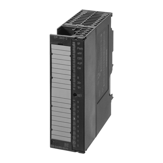
Page 17: Displays And Operator Controls Of The Cp 343-2
1 Technical Description Displays and Operator Controls of the CP 343-2 The following diagram shows the front panel of the CP 343-2 with its indicators and operator controls. The front connector for connecting the AS-i cable is below the cover on the front of the CP 343-2. AS-i+ (brown) AS-i−... - Page 18 1 Technical Description Meaning of the Indicators and Operator Controls: Meaning System fault. The LED is lit when: The CP 343-2 is in the protected mode and an AS-i configuration error has occurred (for example slave failed) The CP detects an internal fault (for example EEPROM defective) In response to a button command, the CP cannot execute the required mode change at the present time (for example, because there is a slave with address 0).
- Page 19 1 Technical Description Meaning Configuration Mode The configuration mode is used during AS-i installation and commissioning. In the configuration mode, the CP 343-2 can exchange data with every AS-i slave connected to the AS-i cable (except for the AS-i slave with address ‘0’). Any AS-i slaves that are added later are detected immediately by the master and activated and included in the cyclic data exchange.
- Page 20 1 Technical Description Characteristics of the Slave Display S If the CP 343-2 is in the configuration mode, all detected AS-i slaves are displayed. S If the CP 343-2 is in the protected mode, all activated AS-i slaves are indicated by the LED being permanently lit. Failed or existing but unconfigured AS-i slaves are indicated by the corresponding LED flashing.
- Page 21 1 Technical Description Example 3 Indicates that the slave with address 31B is detected and activated. Example 4 Indicates that the slaves with addresses 10B and 17B are detected and activated. Figure 1-5 Examples of the Display of Detected and Activated AS-i Slaves on the Front Panel of the CP 343-2 CP 343−2 / CP 343−2 P AS−Interface Master Release 08/2008...
-
Page 22: Configuring Using Buttons
1 Technical Description Configuring using Buttons Preparation for Button Configuration Make sure that the following situation applies: S The PLC CPU must be switched to STOP. S The CP 343-2 and all AS-i slaves must be connected to the AS-interface and supplied with power. -
Page 23: Modes
1 Technical Description Modes The CP recognizes two modes: S Configuration mode S Protected mode Configuration mode The configuration mode is used during AS-i installation and startup. You can change the CP module from protected mode (productive operation) to configuration mode with the ”SET” button. (“CM” LED is lit, see Section 1.6). In Configuration mode, the CP can exchange data with every AS-i slave connected to the AS-i cable. -
Page 24: Addressing The Cp 343-2 In The S7 Automation System
1 Technical Description Addressing the CP 343-2 in the S7 Automation System The CP 343-2 can be addressed by the PLC like an analog module with 16 input bytes and 16 output bytes. The CP occupies 16 input bytes and 16 output bytes in the I/O address space of the S7 automation system (analog area on the AS). -
Page 25: Installation And Commissioning
2 Installation and Commissioning This chapter explains how to install and commission the module. Safety Warnings Warning When used under hazardous conditions (zone 2), the devices must be installed in an enclosure. To comply with ATEX95 (EN 60079-15), this enclosure must meet the requirements of at least IP54 in compliance with EN 60529. -
Page 26: Installing And Commissioning The Cp
2 Installation and Commissioning Ground/Chassis Ground Concept Notice To achieve the noise immunity of the CP 343-2 / CP 343-2 P the AS and AS-i power supply unit must be correctly grounded. Please note the instructions regarding the grounding and chassis ground concept in the SIMATIC S7 installation guidelines;... - Page 27 2 Installation and Commissioning Caution The load capacity of the AS-i contacts is a maximum of 4 A. If this value is exceeded on the AS-i cable, the CP must not be “looped into” the AS-i cable but must be connected by a separate cable( only one pair of CP terminals used). Step Explanation / Meaning 5.
-
Page 28: Configuration With Step
3 Configuration with STEP 7 This chapter explains how to configure the CP with STEP 7 as of V5.2. You will learn the following: S What basic configuration will need to create for the CP 343–2 and CP 343–2 P S What other configuration options the CP 343–2 P provides General Information on Configuring the CP 343-2 with STEP 7... - Page 29 3 Configuration with STEP 7 Configuring Properties of the CP 343-2 / CP 343-2 P To view general information, addresses, and operating parameters and to configure or modify them, change to the Properties dialog of the CP 343-2 / CP 343-2 P. S “General”...
-
Page 30: Extra Configuration Of The Cp 3 43-2 P
3 Configuration with STEP 7 Extra Configuration of the CP 3 43-2 P Note The information in Section 3.3 relates only to the CP 343-2 P! 3.3.1 Configuring in STEP 7 − Operating Parameters S ”Operating Parameters” tab The diagnostic interrupt can be se- lected here for the protected mode. -
Page 31: Configuring As-I Slaves
3 Configuration with STEP 7 3.3.2 Configuring AS-i Slaves Notice A configuration of the AS-i slaves set by STEP 7 and downloaded to the S7 station is transferred from the CPU to the CP 343-2 P when the S7 station starts up. Any configuration set with the buttons is then overwritten. - Page 32 S Siemens Slaves As of STEP 7 version 5.3.3, you have the option of simple configuration of slaves from Siemens AG, by selecting the relevant order number from the drop-down list. As an alternative, you can open the slave selection dialog with the “Selection”...
- Page 33 3 Configuration with STEP 7 Standard AS-i Slave The AS-i standard slave can only be placed at an AS-i address in the A area. This address is then no longer available in the B area. Enter the following vendor information for the AS-i slaves in this area: I/O configuration: standardized meaning;...
- Page 34 3 Configuration with STEP 7 Configuring Analog Slaves as Standard Slaves If you want to configure an analog slave with more than two channels, use the AS-i standard slave. You then set the properties of the analog interface using the combination of the I/O configuration and the three ID codes.
- Page 35 3 Configuration with STEP 7 AS-i A/B Slave The AS-i A/B slave can either be placed at an AS-i address in the A or B area. The B area can be used only when no AS-i standard slave is placed in the A area. The parameters in this area specify the slave profile.
- Page 36 3 Configuration with STEP 7 Slaves Complying with AS-i Specification V3 AS-i slaves complying with AS-i Specification V3 (combined transaction type (CTT) 2−5) are supported by the CP as of firmware version V3.0. You can access the analog values of these slaves using data records 140 to 147. Notice In the corresponding digital values, STEP 7 does not indicate the correct number of bits.
- Page 37 3 Configuration with STEP 7 Table 3-1 shows the relevant bits of the CTT slaves. Table 3-1 Slave in the Type, IO.ID.ID2 Relevant bits Non-relevant bits example (see figure) Slave 1A CTT2, S−7.5.5 I0.0...I0.1 I0.2...I0.3 Q0.2...Q0.3 Q0.0...Q0.1 Slave 2A CTT2, S−7.A.5 I1.4...I1.5 I1.6...I1.7 Q1.6...
-
Page 38: Uploading The Actual Configuration To The Pg (Cp 3 43-2 P Only)
3 Configuration with STEP 7 Uploading the Actual Configuration to the PG (CP 3 43-2 P only) Aims You can upload the current actual configuration over the CP 343–2 P to the open STEP 7 project. This allows you to S read in a complex configuration and use it as a basis for a further configuration in STEP 7 S check a current configuration. -
Page 39: Data Exchange Between User Program And As−I Slaves
4 Data Exchange between User Program and AS−i Slaves This chapter provides you with the information you require to access the data of the AS-i slaves from the PLC user program via the CP 343-2. The chapter explains the transfer of the following: S Binary values of the standard or A slaves via the PLC I/Os S Binary values of the B slaves by reading or writing data record 150 S Analog values of the AS-i analog slaves complying with profile 7.3/7.4 by... -
Page 40: Addressing The Standard Or A Slaves With The Plc
4 Data Exchange between User Program and AS−i Slaves 4.1.1 Addressing the Standard or A Slaves with the PLC Each standard or A slave on the AS-i cable is assigned four bits (a nibble) by the CP 343-2. The PLC can write (slave output data) and read (slave input data) this nibble. - Page 41 4 Data Exchange between User Program and AS−i Slaves Example of a Configuration Figure 2−2 shows an example of the PLC CPU addressing 4 standard or A slaves. The base addresses m = 256 for the I/O data are configured in STEP 7. The bits relevant for the user program are shown on a gray background.
-
Page 42: Accessing Binary Data Of Standard Or A Slaves
4 Data Exchange between User Program and AS−i Slaves 4.1.2 Accessing Binary Data of Standard or A Slaves The bits of the AS-i slaves are accessed using S7 load and transfer commands, such as: L PIW X L PID X T PQW X T PQD X X stands for the byte address on the CP 342-2. - Page 43 4 Data Exchange between User Program and AS−i Slaves If you require bit access to slave data, you can, for example, use the strategy shown in the following program example of a CP with base address 256: Table 4-1 Explanation //Read in binary input data of standard/A slaves PID 256 DB20.DBD 0...
-
Page 44: Exchanging As-I Binary Values With B Slaves
4 Data Exchange between User Program and AS−i Slaves Exchanging AS-i Binary Values with B Slaves Interface between PLC CPU and CP 343-2 You access the binary values of B slaves in the user program using the system function blocks SFC 58 / SFC 59 (”write_data_record” / “read_data_record”). For this function, you always use data record number 150. -
Page 45: How The Plc Addresses The Slaves
4 Data Exchange between User Program and AS−i Slaves 4.2.1 How the PLC Addresses the Slaves The CP 343-2 manages the binary data of the B slaves in two 16-byte long areas (one area for the input data and one area for the output data). The structure of these areas corresponds to the structure of the binary data for the standard or A slaves. -
Page 46: Accessing Binary Data Of B Slaves
4 Data Exchange between User Program and AS−i Slaves 4.2.2 Accessing Binary Data of B Slaves The following sample program illustrates access to the binary data of B slaves. Table 4-2 Explanation //Read in binary input data of the B slaves: CALL SFC 59 //RD_REC :=TRUE... -
Page 47: Points To Note About Binary Data Of Analog Slaves
4 Data Exchange between User Program and AS−i Slaves Points to Note about Binary Data of Analog Slaves 4.3.1 Point to Note About Analog Slaves If you use slaves complying with CTT 1−5, all or some I/O bits may be used for special transfer functions. - Page 48 4 Data Exchange between User Program and AS−i Slaves Analog PLC CPU CP 343-2 slaves write_record DSNR 140−147 Í Í Í Data records AS-i Í Í Í Î Î Î 140−147 for slave 1 Data area for analog Í Í Í Í Î...
- Page 49 4 Data Exchange between User Program and AS−i Slaves Table 4-3 Accessing Analog Values using Data Records Byte addresses occupied by analog values in the data record AS-i slave DS 140 DS 141 DS 142 DS 143 DS 144 DS 145 DS 146 DS 147 address...
- Page 50 4 Data Exchange between User Program and AS−i Slaves Table 4-4 Address Area for the Analog Values of an AS-i Slave Byte no. (start address + offset) Analog value channel Start address + 0 Channel 1 / high byte Start address + 1 Channel 1 / low byte Start address + 2 Channel 2 / high byte...
- Page 51 4 Data Exchange between User Program and AS−i Slaves Special cases when transferring analog values in the output direction S The following applies in the output direction: S With firmware version V2.x, the AS−i master interrupts the transfer of the analog output values when the CPU is in STOP.
- Page 52 4 Data Exchange between User Program and AS−i Slaves 4.4.2 Programming Examples Table 4-5 Explanation //Read in analog input data for slave 5: Call SFC 59 //RD_REC :=TRUE //Permanent trigger IOID :=B#16#54 //Fixed value LADDR :=W#16#100 //CP address (here 256 dec.) RECNUM :=B#16#8D //DSNR=141 (analog data slave 5...) RET_VAL :=MW14...
- Page 53 5 Using the Command Interface Via the command interface, you can control the response of the AS-i master completely from within your user program. This chapter contains the information you require to access the command interface of the CP 343-2. Description of FC “ASI_3422”...
- Page 54 5 Using the Command Interface Call Interface ASI_3422 BOOL DONE BOOL BOOL STARTUP ERROR BOOL WORD LADDR SEND RECV DWORD STATUS DWORD Table 6-1 Formal Parameters Name Para Type Data Type Memory Area Remarks BOOL I,Q,M,D,L,constant As long as ACT = 1, command processing is started provided no other call is being processed.
- Page 55 5 Using the Command Interface Table 6-1 Formal Parameters, continued Name Para Type Data Type Memory Area Remarks STATUS DWORD 1st word: Job status / error code (see Table 6-2); For ’job terminated with error’, an error code is generated that describes the error in greater detail.
- Page 56 5 Using the Command Interface The DONE, ERROR and STATUS parameters remain unchanged until the next job is processed. DONE ERROR STATUS 8181h 0000h 8181h 0000h 8181h 8181h 8181h 8381h 0000h 0000h Figure 6-1 Table 6-2 Error Coding DONE ERROR STATUS Meaning 0000...
- Page 57 5 Using the Command Interface Table 6-2 Error Coding, continued DONE ERROR STATUS Meaning 80C6 Data record transfer aborted due to priority class abort (warm restart or background) of the distributed I/Os. 8181 Job active (no error) 8182 ID from block execution with STARTUP=TRUE (not an error) 8184 Data type of the RECV formal parameter illegal...
- Page 58 5 Using the Command Interface Table 6-2 Error Coding, continued DONE ERROR STATUS Meaning 8F29 Alignment error writing a parameter This error code indicates that the reference to a parameter is a bit address other than 0. 8F30 The parameter is in the write-protected global DB 8F31 The parameter is in the write-protected instance DB This error code indicates that a parameter is located in a...
- Page 59 5 Using the Command Interface Description of the AS-i Slave Commands Overview This section describes the command calls that can be sent by the user program to the CP 343-2. With these command calls, the CP 343-2 provides the complete functionality of the master profile M4 of the AS-i master specification.
- Page 60 5 Using the Command Interface Table 6-3 AS-i Slave Commands, continued Name Parameter Return Coding Get_LPS, Get_LAS, Get_LDS, Get_Flags LDS, LAS, LPS, flags −> described in section 5.2.16 Get_Extended_Total_Configuration Actual configuration, current parameters, −> described in section 5.2.17 LAS, flags Store_Extended_Total_Configuration Total −>...
- Page 61 5 Using the Command Interface Byte Meaning Command number Job data q+... Job data q = base address of the send buffer on the DP master General Structure of the Receive Buffer The basic structure of the response buffer is shown below. The bytes only relevant with certain commands are shown on a gray background.
- Page 62 5 Using the Command Interface 5.2.1 Set_Permanent_Parameter Meaning With this call, a parameter value for the specified AS-i slave is configured on the CP 343-2. The value is stored permanently in the EEPROM of the CP 343-2. The configured parameter is not transferred immediately by the CP 343-2 to the AS-i slave.
- Page 63 5 Using the Command Interface 5.2.2 Get_Permanent_Parameter Meaning With this call, a slave-specific parameter value stored on the EEPROM of the CP 343-2 is read. Structure of the Job Data in the Send Buffer Byte Meaning Command number: 01 Slave address Structure of the Response Data in the Receive Buffer Byte Meaning...
- Page 64 5 Using the Command Interface 5.2.3 Write_Parameter Purpose of the Command The AS-i slave parameter value transferred with the command is passed on to the addressed AS-i slave. The parameter is stored on the CP 343-2 only temporarily and is not entered as a configured parameter in the EEPROM! The AS-i slave transfers its current parameter value in the response (parameter echo).
- Page 65 5 Using the Command Interface 5.2.4 Read_Parameter Meaning This call returns the current parameter value (actual parameter) of an AS-i slave sent by the CP 343-2. This value must not be confused with the parameter echo that is supplied by the AS-i slave as a response to the write_parameter job.
- Page 66 5 Using the Command Interface 5.2.5 Store_Actual_Parameters Meaning With this call, the configured parameters stored on the EEPROM are overwritten with the current, permanently stored (actual) parameters; in other words, the parameters of all the AS-i slaves are configured. For AS-i slaves that comply with the AS-i slave standard profile 7.4, the AS-i master manages the AS-i slave parameter assignment itself.
- Page 67 5 Using the Command Interface 5.2.6 Set_Extended_Permanent_Configuration Meaning This call sets the following configuration data for the addressed AS-i slave. S I/O configuration S ID code S Extended ID1 code S Extended ID2 code The configuration data are stored permanently on the EEPROM of the CP 343-2 and are used as the expected configuration by the AS-i master in the protected mode.
- Page 68 5 Using the Command Interface 5.2.7 Get_Extended_Permanent_Configuration Meaning This call reads the following configuration data (configured data) of an addressed AS-i slave stored on the EEPROM of the AS-i master . S I/O configuration S ID code S Extended ID1 code S Extended ID2 code The configuration data are specified by the manufacturer of the AS-i slave.
- Page 69 5 Using the Command Interface 5.2.8 Store_Actual_Configuration Purpose of the Command With this call, the (actual) configuration data (I/O configuration, ID code, extended ID1 code and extended ID2 code) of all AS-i slaves are stored permanently in the EEPROM as the (expected) configuration data. The list of activated AS-i slaves (LAS) is adopted in the list of permanent AS-i slaves (LPS).
- Page 70 5 Using the Command Interface 5.2.9 Read_Extended_Actual_Configuration Purpose of the Command With this call, the following configuration data of an addressed AS-i slave obtained by the AS-i master on the AS-Interface are read. S I/O configuration S ID code S Extended ID1 code S Extended ID2 code The configuration data are specified by the manufacturer of the AS-i slave.
- Page 71 5 Using the Command Interface 5.2.10 Set_LPS Purpose of the Command With this call, the list of configured AS-i slaves is transferred for permanent storage in the EEPROM of the master. When this command is executed, the AS-i master changes to the of fline phase and then changes back to the normal mode (warm restart on the AS-i master).
- Page 72 5 Using the Command Interface 5.2.11 Set_Offline_Mode Meaning This call switches between the online and offline mode. The online mode is the normal operating situation for the AS-i master. Here, the following jobs are processed cyclically: S During the data exchange phase, the fields of the output data are transferred to the slave outputs for all AS-i slaves in the LAS.
- Page 73 5 Using the Command Interface 5.2.12 Select Autoprogramming Meaning This call can enable or disable the “automatic address programming” function (see also Section 7.1). The AUTO_ADDR_ENABLE bit is stored permanently; in other words, it is retained after a warm/hot restart on the AS-i master. Structure of the Job Data in the Send Buffer Byte Meaning...
- Page 74 5 Using the Command Interface 5.2.13 Set_Operation_Mode Purpose of the Command This call changes the module between the configuration mode and the protected mode. In the protected mode, only AS-i slaves are activated that are entered in the LPS and whose expected and actual configurations match, in other words, when the I/O configuration and ID codes of the detected AS-i slaves are identical to the configured values.
- Page 75 5 Using the Command Interface 5.2.14 Change_AS-I_Slave_Address Purpose of the Command With this call, the AS-i address of an AS-i slave can be modified. This call is mainly used to add a new AS-i slave with the default address “0” to the AS-Interface.
- Page 76 5 Using the Command Interface 5.2.15 Get_AS-i_Slave_Status Meaning With this call, the status register of the addressed AS-i slave can be read out. Depending on the type of AS-i slave, the flags of the status register have the following meaning: Status AS-i slave complying with standard 2.0 AS-i slave complying with standard...
- Page 77 5 Using the Command Interface 5.2.16 Get_LPS, Get_LAS, Get_LDS, Get_Flags Meaning With this call, the following entries are read out of the CP 343-2: S The list of active AS-i slaves (LAS) S The list of detected AS-i slaves (LDS) S The list of permanent AS-i slaves (LPS) S The flags according to the AS-i slave specification Structure of the Job Data in the Send Buffer...
- Page 78 5 Using the Command Interface Byte Meaning Bit 7 Bit 6 Bit 5 Bit 4 Bit 3 Bit 2 Bit 1 Bit 0 LDS slave LDS slave LDS slave LDS slave LDS slave LDS slave LDS slave LDS slave reserved LDS slave LDS slave LDS slave...
- Page 79 5 Using the Command Interface Flag 1 Flag 2 Bit Number Meaning Bit Number Meaning OFFLINE_READY OFFLINE INTERNAL NORMAL_MODE EEPROM_OK CONFIG_MODE AUTO_ADDR_ENABLE AUTO_ADDR_AVAIL PERIPHERY_FAULT AUTO_ADDR_ASSIGN reserved LDS_0 reserved CONFIG_OK MPO startup Meaning of the Flags Flag Meaning OFFLINE_READY The flag is set when the offline phase is active. This flag is set when the voltage on the AS-i cable is too low.
- Page 80 5 Using the Command Interface 5.2.17 Get_Extended_Total_Configuration Meaning With this command, the following data are read from the CP 343-2: S The list of active AS-i slaves (LAS) This indicates which of the connected AS-i slaves are activated. S The current configuration data of the connected AS-i slaves (I/O configuration and ID code).
- Page 81 5 Using the Command Interface Byte Meaning Bit 7 Bit 6 Bit 5 Bit 4 Bit 3 Bit 2 Bit 1 Bit 0 LAS slave LAS slave LAS slave LAS slave LAS slave LAS slave LAS slave LAS slave LAS slave LAS slave LAS slave LAS slave...
- Page 82 5 Using the Command Interface ID_CODE slave 22 I/O configuration slave 22 Ext ID1 slave 22 Ext ID2 slave 22 ID_CODE slave 23 I/O configuration slave 23 Ext ID1 slave 23 Ext ID2 slave 23 ID_CODE slave 24 I/O configuration slave 24 Ext ID1 slave 24 Ext ID2 slave 24 ID_CODE slave 25...
- Page 83 5 Using the Command Interface ID_CODE slave 15B I/O configuration slave 15B Ext ID1 slave 15B Ext ID2 slave 15B ID_CODE slave 16B I/O configuration slave 16B Ext ID1 slave 16B Ext ID2 slave 16B ID_CODE slave 17B I/O configuration slave 17B Ext ID1 slave 17B Ext ID2 slave 17B ID_CODE slave 18B...
- Page 84 5 Using the Command Interface reserved Parameters slave 1B Parameters slave 2B Parameters slave 3B Parameters slave 4B Parameters slave 5B Parameters slave 6B Parameters slave 7B Parameters slave 8B Parameters slave 9B Parameters slave 10B Parameters slave 11B Parameters slave 12B Parameters slave 13B Parameters slave 14B Parameters slave 15B...
- Page 85 5 Using the Command Interface 5.2.18 Store_Extended_Total_Configuration Meaning With this call, the required total configuration of the AS interface is transferred to the AS-i master and stored permanently in the EEPROM as the expected configuration. This configures the CP 343-2. The following data are transferred: S The list of configured AS-i slaves specifying the AS-i slaves that can be activated by the AS-i master in the protected mode.
- Page 86 5 Using the Command Interface Byte Meaning Bit 7 Bit 6 Bit 5 Bit 4 Bit 3 Bit 2 Bit 1 Bit 0 LPS slave LPS slave LPS slave LPS slave LPS slave LPS slave LPS slave LPS slave LPS slave LPS slave LPS slave LPS slave...
- Page 87 5 Using the Command Interface ID_CODE slave 22 I/O configuration slave 22 Ext ID1 slave 22 Ext ID2 slave 22 ID_CODE slave 23 I/O configuration slave 23 Ext ID1 slave 23 Ext ID2 slave 23 ID_CODE slave 24 I/O configuration slave 24 Ext ID1 slave 24 Ext ID2 slave 24 ID_CODE slave 25...
- Page 88 5 Using the Command Interface ID_CODE slave 15B I/O configuration slave 15B Ext ID1 slave 15B Ext ID2 slave 15B ID_CODE slave 16B I/O configuration slave 16B Ext ID1 slave 16B Ext ID2 slave 16B ID_CODE slave 17B I/O configuration slave 17B Ext ID1 slave 17B Ext ID2 slave 17B ID_CODE slave 18B...
- Page 89 5 Using the Command Interface reserved Parameters slave 1B Parameters slave 2B Parameters slave 3B Parameters slave 4B Parameters slave 5B Parameters slave 6B Parameters slave 7B Parameters slave 8B Parameters slave 9B Parameters slave 10B Parameters slave 11B Parameters slave 12B Parameters slave 13B Parameters slave 14B Parameters slave 15B...
- Page 90 5 Using the Command Interface 5.2.19 Write_Extended_Parameter_List Meaning With this command, the parameters for all slaves are transferred to the AS-i master. The AS-i master transfers only the parameters that have changed; in other words, that differ from the previously set (actual) parameters to the AS-i slaves.
- Page 91 5 Using the Command Interface 5.2.20 Read_Extended_Parameter_Echo_List Meaning The read parameter echo list call outputs the echo values of all AS-i slaves. The echo values of an AS-i slave originate from the last parameter call sent to this AS-i slave. Structure of the Job Data in the Send Buffer Byte Meaning...
- Page 92 5 Using the Command Interface 5.2.21 Read_Write_CTT2_request Meaning Using this call, a CTT2 request according to AS-i slave profile “CombinedTranslationType2” can be sent to the AS-i master as a byte string. This forwards the string bytes to the AS-i slave address specified in the send buf fer. With this call, a send buffer with a maximum of 223 bytes is transferred to the AS-i master.
- Page 93 5 Using the Command Interface 5.2.22 Read_Version_ID Meaning This call reads out the version ID of the firmware of the AS-i master . Structure of the Job Data in the Send Buffer Byte Meaning Command number: 14 The response of the AS-i master contains the name and the firmware version number.
- Page 94 5 Using the Command Interface 5.2.23 Read_AS-i_Slave_ID Meaning With this call, the ID code of an AS-i slave can be read out directly over the AS-i cable. The call is intended for diagnostic purposes and is not required in the normal master mode.
- Page 95 5 Using the Command Interface 5.2.24 Read_AS-i_Slave_Extended_ID1 Meaning With this call, the extended ID1 code of an AS-i slave can be read out directly over the AS-i cable. The call is intended for diagnostic purposes and is not required in the normal master mode.
- Page 96 5 Using the Command Interface 5.2.25 Write_AS-i_Slave_Extended_ID1 Meaning With this call, the extended ID1 code of an AS-i slave with address “0” can be written directly over the AS-i cable. The call is intended for diagnostic purposes and is not required in the normal master mode. The AS-i master passes on the extended ID1 code to the AS-i slave without any plausibility check.
- Page 97 5 Using the Command Interface 5.2.26 Read_AS-i_Slave_Extended_ID2 Meaning With this call, the extended ID2 code of an AS-i slave can be read out directly over the AS-i cable. The call is intended for diagnostic purposes and is not required in the normal master mode.
- Page 98 5 Using the Command Interface 5.2.27 Read_AS-i_Slave_I/O Meaning With this call, the I/O configuration of an AS-i slave can be read out directly over the AS-i cable. The call is intended for diagnostic purposes and is not required in the normal master mode. Structure of the Job Data in the Send Buffer Byte Meaning...
- Page 99 5 Using the Command Interface 5.2.28 Get_LPF Meaning With this call, the list of peripheral faults (LPF) signaled by the AS-i slaves is read out from the AS-i master. The LPF is updated cyclically by the AS-i master. Whether and when as AS-i slave signals faults of the attached peripherals (for example wire break) can be found in the description of the AS-i slave.
- Page 100 5 Using the Command Interface 5.2.29 Write_AS-i_Slave_Parameter_String Meaning With this call, a parameter string complying with AS-i slave profile 7.4 can be sent to the AS-i master that passes on the string to the AS-i slave address specified in the send buffer. With this call, a send buffer with a maximum of 223 bytes is transferred to the AS-i master.
- Page 101 5 Using the Command Interface 5.2.30 Read_AS-i_Slave_Parameter_String Meaning With this call, a parameter string complying with AS-i slave profile 7.4 can be read from the AS-i slave with the AS-i slave address specified in the send buffer. The AS-i master supplies up to 221 bytes of response data. The number of parameter bytes actually sent by the AS-i slave is signaled by the AS-I master in byte 0 of the receive buffer (number of parameter bytes).
- Page 102 5 Using the Command Interface 5.2.31 Read_AS-i_Slave_ID_String Meaning With this call, an identification string complying with the AS-i slave profile 7.4 can be read from the AS-i slave with the AS-i slave address specified in the send buffer. The AS-i master supplies up to 221 bytes of response data. The number of ID bytes actually sent by the AS-i slave is signaled by the AS-i master in byte 0 of the receive buffer (number of ID bytes).
- Page 103 5 Using the Command Interface 5.2.32 Read_AS-i_Slave_Diagnostic_String Meaning With this call, a diagnostic string complying with AS-i slave profile 7.4 can be read from the AS-i slave with the AS-i slave address specified in the send buffer. The AS-i master supplies up to 221 bytes of response data. The number of diagnostic bytes actually sent by the AS-i slave is signaled by the AS-i master in byte 0 of the receive buffer (number of diagnostic bytes).
- Page 104 6 Diagnostics and Interrrupts of the CP 343-2 In the protected mode, the CP 343-2 signals a diagnostic interrupt whenever the configuration on the AS-Interface is changed. Changes in the configuration might be that voltage on the AS-Interface is too low (AS-i Power Fail) or that configuration errors have been detected (missing, incorrect or existing but unconfigured AS-i slaves).
- Page 105 6 Diagnostics and Interrrupts of the CP 343-2 CP-external interrupt events: S All changes to the AS-i slave configuration in the protected mode S AS-i Power Fail in the protected mode CP-internal interrupt events: S EEPROM Error Note CP-internal interrupt events are always events entering the state. After a CP-internal interrupt event occurs, the group error bit remains = TRUE.
- Page 106 6 Diagnostics and Interrrupts of the CP 343-2 Response to Interrupts in Different CP Operating States The CP 343-2 generates diagnostic interrupts triggered by external interrupt events only in the protected mode and not in the configuration mode. If the PLC CPU changes to STOP, the internal interrupt history is reset; in other words, the bit OB82_MDL_DEFECT and all other error bits in DS 0 are reset.
- Page 107 6 Diagnostics and Interrrupts of the CP 343-2 Byte Variable Name Data Type Meaning OB82_MDL_TYPE BOOL with the CP with firmware V2.x: always “0” with the CP as of firmware V3.0: at least 1 AS−i slave is signaling an IO error. OB82_MDL_TYPE BOOL reserved...
- Page 108 6 Diagnostics and Interrrupts of the CP 343-2 Reading the Diagnostic Data Record DS 1 The CP 343-2 continuously updates a delta list containing all the slaves that exist but that differ from the configuration; in other words, they are missing, incorrect, or not configured (each slave is assigned a bit in the delta list: 0 = no error;...
- Page 109 6 Diagnostics and Interrrupts of the CP 343-2 Programming Example The following example illustrates how you can react to a diagnostic interrupt of the CP 343-2 in OB82 by reading the data record (DS1). Table 8-1 Explanation OB82 local data: 20.0 temp t_header...
- Page 110 6 Diagnostics and Interrrupts of the CP 343-2 Diagnostic Interrupts: Some Examples It is assumed that slaves 1 and 12 were configured using the buttons on the CP 343-2 and that the CP 343-2 is in the protected mode. If slave 7 fails, the CP 343-2 generates a diagnostic interrupt. The PLC operating system then enters the “module fault”...
- Page 111 7 Dealing with Problems / Error Displays This chapter contains information about special operating states of the CP 343-2. It is intended to help you to deal with problems. Replacing a Defective AS-i Slave/Automatic Address Programming Simple Replacement of AS-i Slaves Using the automatic address programming function, you can replace failed AS-i slaves extremely simply.
- Page 112 7 Dealing with Problems / Error Displays Error Displays/Remedying Errors The following table lists the possible causes of errors that can occur when operating the CP 343-2 and how to remedy the problem. Table 10-1 Error Possible Cause Remedy APF LED lit Power requirements of the AS-i Check the power requirements of slaves are too high.
- Page 113 7 Dealing with Problems / Error Displays Table 10-1 , continued Error Possible Cause Remedy The CER display flickers, in other Bad contact Check the electrical connections words a configured slave is lost of the AS-i slaves. sporadically. sporadically. Interference on the AS-i cable. Check the correct grounding of the CP 343-2 module and check the AS-i cable.
- Page 114 7 Dealing with Problems / Error Displays Table 10-1 , continued Error Possible Cause Remedy The replaced AS-i slave is not cor- Check the connections of the rectly connected or is defective. slave and if necessary replace the slave. The “CER” LED and the LEDs of An extender is installed in the AS- Correct the connections on the active AS-i slaves flicker irregu-...
- Page 115 A AS-Interface Protocol Implementation Conformance Statement (PICS) PICS for the CP 343−2 Table K-1 Vendor SIEMENS AG Product Name CP 343-2 Order Number 6GK7 343−2AH11−0XA0 Version V3.0 Master Profile Date 03.03.2008 List of Available Master Functions Symbols in column 3 (M4)
- Page 116 A AS-Interface Protocol Implementation Conformance Statement (PICS) Table K-2 PICS, (continued) Function or Call on the Host Interface Comment / Function implemented by (symbolic representation) Status = Store_Actual_Parameters() see Section 5.2 Status = see Section 5.2 Set_Permanent_Configuration(Addr, Config) Status, Config = see Section 5.2 Get_Permanent_Configuration(Addr) Status = Store_Actual_Configuration()
- Page 117 A AS-Interface Protocol Implementation Conformance Statement (PICS) Table K-2 PICS, (continued) Function or Call on the Host Interface Comment / Function implemented by (symbolic representation) 22.1 Status, Resp = − optional command Cmd_Reset_ASI_Slave(Addr, RESET) 22.2 Status, Resp = see Section 5.2 Cmd_Read_IO_Configuration(Addr, CONF) 22.3...
- Page 118 A AS-Interface Protocol Implementation Conformance Statement (PICS) Table K-2 PICS, (continued) Function or Call on the Host Interface Comment / Function implemented by (symbolic representation) Support of Combined transaction type 4 integrated Support of Combined transaction type 5 integrated How the AS-i cycle time depends on the number of connected slaves The AS-i cycle time can be calculated using the following formula: If 5 or more AS-i slaves are activated: = (1 + number of activated AS-i slaves) x 154 ms...
- Page 119 SIMATIC NET Industrielle Kommunikation für Automation and Drives Catalog IK PI The catalog can be ordered from your local SIEMENS branch office or distributor. SIMATIC S7 S7−300 Automation System − CPU 31xC and 31x Installation: Operating Instructions (ID: 13008499) −...
- Page 120 Components for Integrated Automation, Catalog ST70”. You can order these catalogs and obtain additional information from your local SIEMENS branch or distributor. You will find many of the Siemens AG manuals on the Internet pages of Siemens Customer Support for automation: http://support.automation.siemens.com Enter the ID of the manual in the search box.
- Page 121 The product listed above meets the requirements of the EC Directive EMC 2004/108/EEC “Electromagnetic Compatibility”. The EC Declaration of Conformity is available for the responsible authorities according to the above mentioned EC Directive at the following address: Siemens Aktiengesellschaft Bereich Automatisierungs− und Antriebstechniktechnik Industrielle Kommunikation (A&D SC IC) Postfach 4848 D−90327 Nürnberg, Germany...
- Page 122 D Glossary AS-i Power Fail Flag or LED display that indicates that the power supply on the AS-i cable is too low or has failed (for example failure of the AS-i power supply unit). Automation system AS-i (AS-Interface) Actuator-sensor interface. A network system for the lowest field area of the automation range.
- Page 123 D Glossary AS-i module For the AS-Interface, a module concept has been defined that allows the block- like linking of AS-i slaves − sensors and actuators − via AS-i modules. The following types of module exist: The active AS-i module with an integrated AS-i chip; using this, up to four con- ventional sensors and actuators can be connected.
- Page 124 D Glossary List of activated slaves List of detected slaves. List of permanent slaves. Nibble A nibble is a unit of information consisting of four bits. Standard AS-i master Up to 31 standard slaves or slaves with the extended addressing mode (A slaves only) can be attached to a standard AS-i master.
- Page 125 Response to interrupts, in different CP CTT slaves, 36 operating states, 106 Diagnostic data record, DS1, 108 Siemens slave, 32 Diagnostic interrupt processing, sequence, 105 Signal sequence of the formal parameters Diagnostic OB, OB82, 106 ACT, DONE, ERROR and STATUS, 55...
- Page 126 Technical specifications, 15 Upload to PG, 38 User program, 55 CP 343−2 / CP 343−2 P AS−Interface Master Release 08/2008 C79000−G8976−C149−04...
- Page 127 Technical description Using the command interface Dealing with problems / error displays AS-Interface Supplement to manual AS-Interface Master CP 343-2 / CP 343-2 P for SIMATIC S7 Operating Manual 08/2010 A5E03006584020A-01...
- Page 128 Note the following: WARNING Siemens products may only be used for the applications described in the catalog and in the relevant technical documentation. If products and components from other manufacturers are used, these must be recommended or approved by Siemens. Proper transport, storage, installation, assembly, commissioning, operation and maintenance are required to ensure that the products operate safely and without any problems.
- Page 129 Table of contents Technical description ..........................5 1.10 AS-Interface operation with 24 V voltage (AS-i Power24V) ............5 Using the command interface ........................9 Description of FC "ASI_3422" (supplements) ................9 Description of the AS-i-slave commands (supplements) .............10 5.2.17 Read_extended_total_configuration (command number: 39 ) ...........
- Page 130 CP 343-2/CP 343-2 P AS-Interface Master for SIMATIC S7 Supplement to Operating Manual, 08/2010, A5E03006584020A-01...
-
Page 131: Technical Description
Technical description 1.10 AS-Interface operation with 24 V voltage (AS-i Power24V) Description The AS-Interface cable transports communication signals as well as supply voltage for the modules and sensors / actuators (depending on module type). The nominal supply voltage is normally 30 V DC and is supplied by an AS-Interface power supply unit. This power supply unit also contains the data decoupling circuit required to operate the system. - Page 132 Technical description 1.10 AS-Interface operation with 24 V voltage (AS-i Power24V) NOTICE Voltage lower than 22.5 V on the AS-Interface If the voltage on the AS-Interface is less than 22.5 V (+/-1 V), the CP 343−2 / CP 343−2 P generates the message "AS-i POWER FAIL" (APF) when voltage monitoring is activated (setting in delivery state) and ...
- Page 133 Technical description 1.10 AS-Interface operation with 24 V voltage (AS-i Power24V) Deactivating the voltage monitoring (only on 6GK7 343-2AH01-0XA0 and 6GK7 343-2AH11-0XA0, product version 02): Step Meaning 1: Install the CP as described in Section 2.2. 2: Switch the power supply to the SIMATIC station off and The CP performs a self-test when it powers up.
- Page 134 Technical description 1.10 AS-Interface operation with 24 V voltage (AS-i Power24V) NOTICE Note on step 2: Termination of power-up by pressing the "SET" button: While the CP is powering up, do not press the "SET" button, if you press the "SET" button the CP will switch to a special internal state: An LED running light display is activated (LED "SF"...
-
Page 135: Using The Command Interface
Using the command interface Description of FC "ASI_3422" (supplements) CAUTION If the receive buffer of the FC ASI_3422 is too short, any bordering memory areas are overwritten. The length specification in the ANY pointer of the parameter RECV when calling the FC ASI_3422 is irrelevant. The required length of the receive buffer can be found in the description of the command. -
Page 136: Description Of The As-I-Slave Commands (Supplements)
Using the command interface 5.2 Description of the AS-i-slave commands (supplements) Description of the AS-i-slave commands (supplements) 5.2.17 Read_extended_total_configuration (command number: 39 Supplement: The receive buffer must have a length of 221 bytes (byte 0 to 220). The highest bytes 172 to 220 are reserved and may be overwritten by the AS-i master with zero values. -
Page 137: Dealing With Problems / Error Displays
Dealing with problems / error displays Replacing a defective AS-i slave / automatic address programming 7.1.1 Automatic address programming after failure of one or more AS-i slaves (CP with firmware version V3.1 or higher) AS-i slave replacement with CP 343-2 (6GK7 343-2AH01-0XA0) and CP 343-2 P (6GK7 343-2AH11-0XA0), product version 02/firmware version V3.1 or higher The "Automatic address programming"... - Page 138 Dealing with problems / error displays 7.1 Replacing a defective AS-i slave / automatic address programming Note Exceptions Automatic address programming does not work on the following devices as the internal slaves all have identical identifiers (I/O configuration, ID code, ID2 code, ID1 code). ...
-
Page 139: Automatic Address Programming After Failure Of An As-I Slave (Cp With Firmware Version V3.0 Or Lower)
Dealing with problems / error displays 7.1 Replacing a defective AS-i slave / automatic address programming 7.1.2 Automatic address programming after failure of an AS-i slave (CP with firmware version V3.0 or lower) AS-i slave replacement with ● CP 343-2 (6GK7 343-2AH01-0XA0) and CP 343-2 P (6GK7 343-2AH11-0XA0), product version 01 / firmware version V3.0 or earlier, and ●... -
Page 140: Error Displays/Remedying Errors
Dealing with problems / error displays 7.2 Error displays/remedying errors Error displays/remedying errors 7.2.1 Error displays/remedying errors (incompatibilities) Below are listed possible fault indicators, and potential remedial measures, when operating the CP 343−2 with incompatible slaves. Error Possible cause Remedy CER indicator flickers or lights up, and A connected slave is not compatible Connect only slaves that are...
Need help?
Do you have a question about the SIMATIC NET CP 343-2 and is the answer not in the manual?
Questions and answers