Table of Contents
Advertisement
CP 1542-5
SIMATIC NET
S7-1500 - PROFIBUS
CP 1542-5
Manual
11/2014
C79000-G8976-C326-03
___________________
Preface
___________________
Guide to the documentation
___________________
Product overview
___________________
Functional characteristics
___________________
Requirements for use
___________________
Connecting up /
commissioning
Interrupts, diagnostics
messages, error and
system alarms
___________________
Technical specifications
___________________
Approvals
1
2
3
4
5
6
7
8
Advertisement
Table of Contents

Related Manuals for Siemens PROFIBUS CP 1542-5


Summary of Contents for Siemens PROFIBUS CP 1542-5
- Page 1 ___________________ CP 1542-5 Preface ___________________ Guide to the documentation ___________________ SIMATIC NET Product overview ___________________ Functional characteristics S7-1500 - PROFIBUS CP 1542-5 ___________________ Requirements for use ___________________ Connecting up / commissioning Manual Interrupts, diagnostics messages, error and system alarms ___________________ Technical specifications ___________________ Approvals...
- Page 2 Note the following: WARNING Siemens products may only be used for the applications described in the catalog and in the relevant technical documentation. If products and components from other manufacturers are used, these must be recommended or approved by Siemens. Proper transport, storage, installation, assembly, commissioning, operation and maintenance are required to ensure that the products operate safely and without any problems.
-
Page 3: Preface
You will find the SIMATIC NET glossary here: ● SIMATIC NET Manual Collection or product DVD The DVD ships with certain SIMATIC NET products. ● On the Internet under the following entry ID: 50305045 (http://support.automation.siemens.com/WW/view/en/50305045) CP 1542-5 Manual, 11/2014, C79000-G8976-C326-03... - Page 4 Siemens recommends strongly that you regularly check for product updates. For the secure operation of Siemens products and solutions, it is necessary to take suitable preventive action (e.g. cell protection concept) and integrate each component into a holistic, state-of-the-art industrial security concept.
-
Page 5: Table Of Contents
Table of contents Preface ..............................3 Guide to the documentation ........................7 Product overview ............................ 9 Properties ..........................9 Further functions ........................11 Functional characteristics ........................13 Transmission speeds supported ..................... 13 Characteristic data of the DP interface ................... 13 Characteristics of S7 communication .................. - Page 6 Table of contents CP 1542-5 Manual, 11/2014, C79000-G8976-C326-03...
-
Page 7: Guide To The Documentation
Table 1- 1 Documentation for the CP 1542-5 Topic Documentation Most important contents System descrip- System manual: S7-1500 Automation System Application planning • tion (http://support.automation.siemens.com/WW/vi Installation • ew/en/59191792) Connecting • Commissioning • Module properties Device manual: Power supplies Connecting •... - Page 8 SIMATIC manuals All current manuals for SIMATIC products are available for download free of charge from the Internet (http://www.siemens.com/automation/service&support). CP/CM documentation in the Manual Collection (article number A5E00069051) The "SIMATIC NET Manual Collection" DVD contains the device manuals and descriptions of all SIMATIC NET products current at the time it was created.
-
Page 9: Product Overview
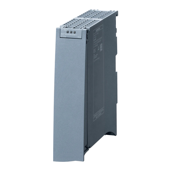
Product overview Properties Article number, validity and product names This description contains information on the following product: CP 1542-5 Article number6GK7 542-5FX00-0XE0 Hardware product version 1 Firmware version V1.0 Communications processor for connecting SIMATIC S7-1500 to PROFIBUS DP. View of the CP ①... - Page 10 – DP master mode for DP slaves complying with the PROFIBUS DPV0 and DPV1 standard – DP master mode for Siemens DP slaves – Direct data exchange (DP slave to DP slave) As a DP master, the CP 1542-5 is capable of enabling direct data exchange for "its"...
-
Page 11: Further Functions
Product overview 2.2 Further functions Further functions Enabling /disabling DP slave - in the standard system DP slaves can be activated and deactivated by the user program using system function D_ACT_DP. Diagnostics requests As a DP master (class 1), the CP 1542-5 supports diagnostics requests of a DP master (class 2). - Page 12 Product overview 2.2 Further functions CP 1542-5 Manual, 11/2014, C79000-G8976-C326-03...
-
Page 13: Functional Characteristics
Measured values of transfer or reaction times Measurements of transfer and reaction times in Ethernet, PROFIBUS and PROFINET networks for a series of configurations can be found on the Internet (http://support.automation.siemens.com/WW/view/en/25209605) Transmission speeds supported The transmission speed is set with the SIMATIC STEP 7 configuration software. -
Page 14: Characteristics Of S7 Communication
Functional characteristics 3.3 Characteristics of S7 communication Diagnostics requests As a DP master (class 1), the CP 1542-5 supports diagnostics requests of a DP master (class 2). DP startup behavior Note Increasing the default value for startup parameters - configuration of the CPU In some situations, it is necessary to increase the default value for the startup parameter "Parameter assignment time for the distributed I/O"... -
Page 15: Requirements For Use
Requirements for use Configuration limits When using the CP type described here, the following limits apply: ● The number of CPs that can be operated in a rack depends on the CPU type being used. Note the information in the documentation of the CPU, see Guide to the documentation (Page 7) Project engineering Configuration and downloading the configuration data... - Page 16 ● Instruction WRREC "Write data record to a DP slave" corresponds to SFC58 in terms of function ● Instruction RALRM "Read interrupt information from a DP slave" - call in an interrupt OB PNO: PROFIBUS Users Organization See also 8797900 (http://support.automation.siemens.com/WW/view/en/8797900) CP 1542-5 Manual, 11/2014, C79000-G8976-C326-03...
-
Page 17: Connecting Up / Commissioning
Connecting up / commissioning Important notes on using the device Safety notices on the use of the device The following safety notices must be adhered to when setting up and operating the device and during all associated work such as installation, connecting up, replacing devices or opening the device. - Page 18 Connecting up / commissioning 5.1 Important notes on using the device WARNING Replacing components EXPLOSION HAZARD SUBSTITUTION OF COMPONENTS MAY IMPAIR SUITABILITY FOR CLASS I, DIVISION 2 OR ZONE 2. WARNING Requirements for the cabinet/enclosure When used in hazardous environments corresponding to Class I, Division 2 or Class I, Zone 2, the device must be installed in a cabinet or a suitable enclosure.
-
Page 19: Installing And Commissioning The Cp 1542-5
Connecting up / commissioning 5.2 Installing and commissioning the CP 1542-5 WARNING Suitable cables for temperatures in excess of 70 °C If the cable or conduit entry point exceeds 70°C or the branching point of conductors exceeds 80°C, special precautions must be taken. If the device is operated at ambient temperatures above 50°C, the permitted temperature range of the selected cable must be suitable for the temperatures actually measured. - Page 20 Connecting up / commissioning 5.2 Installing and commissioning the CP 1542-5 Procedure for installation and commissioning Step Execution Notes and explanations When installing and connecting up, keep to the procedures described for installing I/O modules in the system manual "S7-1500 Automation Sys- tem".
-
Page 21: Replacing A Module Without A Programming Device
Connecting up / commissioning 5.3 Replacing a module without a programming device PROFIBUS interface The table below shows the terminal assignment of the PROFIBUS interface. The assignment corresponds to the standard assignment of RS485 interface. Table 5- 1 Terminal assignment PROFIBUS interface View Signal name Designation... -
Page 22: Mode Of The Cpu - Effect On The Cp
Connecting up / commissioning 5.4 Mode of the CPU - effect on the CP Mode of the CPU - effect on the CP You can change the mode of the CPU between RUN and STOP using the STEP 7 configuration software. Depending on the operating status of the CPU, the CP behaves as described below. -
Page 23: Interrupts, Diagnostics Messages, Error And System Alarms
The status and error displays of the CP 1542-5 are described below. You can find additional information on "Interrupts" in the STEP 7 online help. You can find additional information on "Diagnostics" and "System alarms" in the System diagnostics (http://support.automation.siemens.com/WW/view/en/59192926) function manual. Status and error display of the CP LED display The following figure shows the LEDs of the CP 1542-5 . - Page 24 Interrupts, diagnostics messages, error and system alarms 6.1 Status and error display of the CP Meaning of the LED displays The CP 1542-5 has 3 LEDs to display the current operating status and the diagnostics status and these have the following meanings: (one-color LED: green) •...
-
Page 25: Diagnostics Options
Interrupts, diagnostics messages, error and system alarms 6.2 Diagnostics options Diagnostics options Diagnostics options You have the following diagnostics options available for the module: ● The LEDs of the module For information on the LED displays, refer to the section Status and error display of the CP (Page 23). - Page 26 Interrupts, diagnostics messages, error and system alarms 6.3 DP slave diagnostics User program (DP master) To read out the diagnostics data of the DP slave (DP single diagnostics), use the "DPNRM_DG" instruction on the DP master. Diagnostics interrupts of DP-V1 slaves are evaluated in the user program of the master using the "RALRM"...
-
Page 27: Standard Diagnostics
Interrupts, diagnostics messages, error and system alarms 6.4 Standard diagnostics Standard diagnostics The coding of the standard diagnostics bytes is explained below. Byte 0: Station status 1 Table 6- 3 Structure of station status byte 1 Bit no. Name Explanation Master_Lock The DP slave was assigned parameters by a different DP master. - Page 28 Interrupts, diagnostics messages, error and system alarms 6.4 Standard diagnostics Byte 1: Station status 2 Table 6- 4 Structure of station status byte 2 Bit no. Name Explanation Deactivated The DP slave was identified as being not active in the local parameter record and it is not polled cyclically.
-
Page 29: Device-Specific Diagnostics In Dp-V1
Interrupts, diagnostics messages, error and system alarms 6.5 Device-specific diagnostics in DP-V1 Device-specific diagnostics in DP-V1 There are two variants of device-specific diagnostics with DP-V1 slaves: ● Interrupt type ● Status type The two variants differ from each other in the coding of byte 1, bit 7 of the device-specific diagnostics data. - Page 30 Interrupts, diagnostics messages, error and system alarms 6.5 Device-specific diagnostics in DP-V1 Byte 1: Variant "Status type" Table 6- 7 Structure of byte 1 of the device-specific diagnostics (variant "status type") Bit no. Meaning Value Meaning Status information 6...0 Status_Type - reserved - Status information Modul_Status (see also bytes 4...62)
- Page 31 Interrupts, diagnostics messages, error and system alarms 6.5 Device-specific diagnostics in DP-V1 Byte 3: Variant "Status specifier" Table 6- 9 Structure of byte 3 of the device-specific diagnostics (variant "status specifier") Bit no. Meaning 7...2 - reserved - 1...0 Status_Specifier No further distinction Status appears Status disappears...
-
Page 32: Dp Diagnostics Frames When The Cpu Is In Stop
Interrupts, diagnostics messages, error and system alarms 6.6 DP diagnostics frames when the CPU is in STOP DP diagnostics frames when the CPU is in STOP DP diagnostics frames when the CPU is in STOP All diagnostics frames from DPV0 standard slaves and all DP interrupt frames from DP- S7/DPV1 standard slaves arriving when the CPU is in STOP are forwarded to the CPU. -
Page 33: Technical Specifications
Technical specifications Note the information in the System description of SIMATIC S7-1500 (Page 7). In addition to the information in the system description, the following technical specifications apply to the module. 6GK7 542-5FX00-0XE0 Product type name CP 1542-5 Connection to PROFIBUS 1 x PROFIBUS interface Number •... - Page 34 Technical specifications CP 1542-5 Manual, 11/2014, C79000-G8976-C326-03...
-
Page 35: Approvals
Certificates for shipbuilding and national approvals The device certificates for shipbuilding and special national approvals can be found on the pages of Siemens Automation Customer Support on the Internet (http://support.automation.siemens.com/WW/news/en/10805878) Under this entry, go to the required product and select the following settings: "Entry list" tab >... - Page 36 D-90327 Nürnberg You will find the EC Declaration of Conformity at the following address / under the following entry ID on the Internet (http://support.automation.siemens.com/WW/view/en/16689636) EMC directive The SIMATIC NET S7 CPs listed above are designed for use in an industrial environment.
- Page 37 Approvals Notice for Australia - C-TICK The above listed SIMATIC NET S7 CPs meet the requirements of the standard AS/NZS 2064 (Class A). Notices for Canada This class A digital device meets the requirements of the Canadian standard ICES-003. AVIS CANADIEN Cet appareil numérique de la classe A est conforme à...
- Page 38 Approvals You will find the temperature class on the type plate on the module. WARNING Explosion Hazard - Do not disconnect while circuit is live unless area is known to be non hazardous. Explosion Hazard - Substitution of components may impair suitability for Class I, Division 2. Note This equipment is suitable for use in Class I, Division 2, Group A, B, C, D or non-hazardous locations only.
-
Page 39: Index
Index DP slave, 10, 11 Operation as, 10 DP slave mode, 22 DP slaves ATEX, 18 General characteristic data, 13 Bus topology, 11 EMC - electromagnetic compatibility, 36 Error status codes, 23 Cabinet, 18 Cable length, 13 Cables for temperatures in excess of 70 °C, 19 Approval, 38 Calling program blocks (instructions) for distributed I/O, 16... - Page 40 S7 connections, 14 General characteristic data, 14 S7 routing function, 22 Safety extra low voltage, 17 Safety notices, 17 Siemens DP slave, 10 SIMATIC NET glossary, 3 SIMATIC NET Manual Collection, 8 Startup parameters, 14 Status and error displays, 23...
Need help?
Do you have a question about the PROFIBUS CP 1542-5 and is the answer not in the manual?
Questions and answers