Table of Contents
Advertisement
Advertisement
Table of Contents

Related Manuals for Siemens SINAMICS V60


Summary of Contents for Siemens SINAMICS V60
-
Page 1: Getting Started
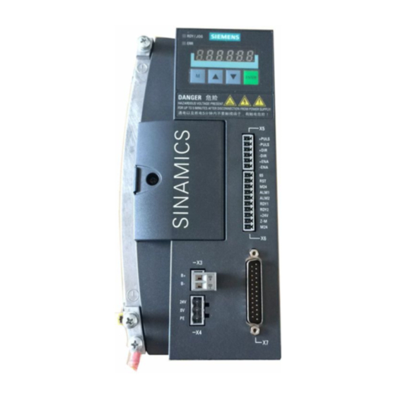
Getting Started Version: 05/2012 SINAMICS V60 Controlled Power Module (CPM60.1) -
Page 2: Table Of Contents
Table of contents General information 1.1 System overview ............EN-3 1.2 Safety notes..............EN-4 1.3 Identification..............EN-6 1.4 Technical data.............. EN-8 Installation 2.1 Mechanical installation..........EN-10 2.1.1 Mounting the drive............EN-10 2.1.2 Mounting the motor............EN-12 2.2 Electrical installation............. EN-12 2.3 Interface definition............ - Page 3 EN-2 SINAMICS V60 Controlled Power Module (CPM60.1) Getting Started...
-
Page 4: General Information
General Information 1.1 System Overview The SINAMICS V60 servo drive system is a new drive system developed by Siemens. It's designed for use with a Siemens SINUMERIK 801 or SINUMERIK 802S base line numerical controller to control the operation of a CNC turning or milling machine, and it can also be connected with a Siemens SIMATIC PLC. -
Page 5: Safety Notes
Keep sufficient clearance between drives, one drive and another device/inner wall of the cabinet. NOTICE Siemens recommends that you tighten the screw on the terminal door of the drive, after you have completed the installation work. EN-4 SINAMICS V60 Controlled Power Module (CPM60.1) Getting Started... - Page 6 Do suppress radio interference according to EN61800, category C3 (for industrial environment only). SINAMICS V60 is an open-loop drive system, so it has no protection against wire breaks. CAUTION The drive must connect to the motor directly with no capacitor, inductor or filter, etc.
-
Page 7: Identification
- 10 m Drive side (to motor brake interface X3) Brake cable (unshielded) Motor side (to motor brake socket) Drive side (to encoder interface X7) Encoder cable (shielded) Motor side (to encoder socket) EN-6 SINAMICS V60 Controlled Power Module (CPM60.1) Getting Started... - Page 8 G: Without key, without brake Rated torque: H: Without key, with brake 4.0 Nm A: With key, without brake 6.0 Nm B: With key, with brake 7.7 Nm 6: 10.0 Nm SINAMICS V60 Controlled Power Module (CPM60.1) Getting Started EN-7...
-
Page 9: Technical Data
Outline dimensions (W x H x D) 106 x 226 x 200 106 x 226 x 200 NOTICE For technical data of the motor, please refer to the Motor Specification delivered with the motor. EN-8 SINAMICS V60 Controlled Power Module (CPM60.1) Getting Started... - Page 10 3AC 380V mains system. The customer may select the right transformer with reference to the table above (Determine the right transformer power based on desired motor combinations) SINAMICS V60 Controlled Power Module (CPM60.1) Getting Started EN-9...
-
Page 11: Mechanical Installation
Minimum mounting clearance To ensure sufficient heat dissipation, please observe the requirements for minimum clearance between drives, one drive and another device/inner wall of the cabinet, as illustrated in the picture below: EN-10 SINAMICS V60 Controlled Power Module (CPM60.1) Getting Started... - Page 12 After the installation, it is recommended that the screws on the terminal covers should be screwed down to ensure the safety. Siemens does not provide the shielded motor cable. Please prepare the shielded motor cable by yourselves for CE certification.
- Page 14 When using the drive together with the SIMATIC PLC, you are recommended to use a standard 24 V DC power supply for the SIMATIC PLC and use a Siemens cable (6ES7298-2DS23-0XA0) to connect the two ones.
- Page 15 M P24V NOTE As 65 signal from SINAMICS V60 drive is recommended for emergency stop, it is not used in SIMATIC PLC/SINAMICS V60 signal cable. For a SIMATIC PLC (S7-200 series), signal PULS can only be connected to output terminal Q0.0 or Q0.1, and terminal Q0.2 or Q0.3 is used for direction output.
- Page 16 24 V (- 15% to +20%). Since the excellent quality of a DC power supply is critical to the stable operation of a drive system, Siemens recommends you to select a SIEMENS DC 24 V stabilized power supply (order number: 6EP1333-3BA00).
-
Page 17: Interface Definition
DIR signals should be more than 16 s. a damage to the Please ensure that all the terminals of interface X5 should be firmly wired, otherwise, it is forbidden to start device. the machine. EN-16 SINAMICS V60 Controlled Power Module (CPM60.1) Getting Started... - Page 18 Encoder power supply GND Motor side Drive side (15-pin socket connector) (25-pin socket connector X7) EP5 5/6/17/18 1/2/3/4 N.C. N.C. Screw type: UNC 4-40 (plug-in terminal block) Tightening torque : 0.5 - 0.6 Nm SINAMICS V60 Controlled Power Module (CPM60.1) Getting Started EN-17...
-
Page 19: Signal Sequence Example
32 ms 65 enable ..16 ms RDY signal ..16 ms ENA enable ..DIR signal 16 ms PULS signal ..Power-off sequence Main power ..0.5 s 24 V ..EN-18 SINAMICS V60 Controlled Power Module (CPM60.1) Getting Started... -
Page 20: Commissioning
The default menu item under current menu level Actual menu display The status menu items Menu Item Preconditions for display of normal status Definition Normal status 8.8.8.8.8.8. S-RUN Alarm status S-A01 SINAMICS V60 Controlled Power Module (CPM60.1) Getting Started EN-19... -
Page 21: Function Menu
X6-"65") or signal of pulse enable (terminal X5-"+ENA"/"-ENA") should be cut off if you try to save the The 2nd default values are the default values of FW V1.6 and the lower. EN-20 SINAMICS V60 Controlled Power Module (CPM60.1) Getting Started... - Page 22 To save the setting permanently, you should use "Save user parameter" menu entry under "Function" main menu. Detailed description of individual parameters can be found in Section 6.2 "Parameter list (Page 44)". SINAMICS V60 Controlled Power Module (CPM60.1) Getting Started EN-21...
-
Page 23: Setpoints From Nc
Encoder revolution (2,500) X, Y, Z (for 802S base line) x Multiplier (4) X, Z (for 801) STEP_RESOL 31400 10,000 Steps per servo motor revolution X, Y, Z (for 802S base line) EN-22 SINAMICS V60 Controlled Power Module (CPM60.1) Getting Started... -
Page 24: First Commissioning
Go to "Func" main menu, select "JOG" -> "JOG RUN". Keep Up or Down key pressed to enable motor trial run. Adjust speed controller performance (P20 & P21) , if necessary. SINAMICS V60 Controlled Power Module (CPM60.1) Getting Started EN-23... -
Page 25: System Commissioning
Refer to Section 3.1.1 for possible causes Start NC operation Are you satisfied with the system performance? Adjust speed controller performance (P20 & P21) as well as position controller performance (P30 & P31), if necessary. EN-24 SINAMICS V60 Controlled Power Module (CPM60.1) Getting Started... -
Page 26: Parameter List
2. The bigger the value, the higher both the gain and rigidity, and at the same pulse command frequency the smaller the position hysteresis. However, excessively high value setting may cause system oscillation or overshooting. 3. The setting depends on specific drive and load. SINAMICS V60 Controlled Power Module (CPM60.1) Getting Started EN-25... - Page 27 This parameter defines the time period when the motor ramps up from 0 rpm to 2,000 rpm or ramps down from 2, 000 rpm to 0 rpm. Reserved for Siemens internal use only Note: The default values in brackets are the second default values. EN-26 SINAMICS V60 Controlled Power Module (CPM60.1) Getting Started...
- Page 28 (See table below) * The data type of D10, D11, D12, D80, D82 is all decimal format. The display value for D50 and D51 respectively varies as the case may require. SINAMICS V60 Controlled Power Module (CPM60.1) Getting Started EN-27...
- Page 29 The point is lit. This point stands for the decimal number. In this example, the value means that the parameter version number is “01.01”. Figure 6-11 Special data displays (D10, D11, D12, D80, D82) EN-28 SINAMICS V60 Controlled Power Module (CPM60.1) Getting Started...
-
Page 30: Led Status Indicators
IGBT becomes overheating Following error exceeds the limit Following error too big t protection Motor load exceeds nominal motor torque Enable signal from Terminal 65 is lost during normal drive running Emergency stop SINAMICS V60 Controlled Power Module (CPM60.1) Getting Started EN-29... - Page 31 Press Enter key on Free stop blocked load the operator panel or terminal RST of Overload 1. lighten the load X6 interface 2. use another drive and motor with bigger power EN-30 SINAMICS V60 Controlled Power Module (CPM60.1) Getting Started...
- Page 32 Press Enter key on when the motor is running stop (the terminal the operator panel motor will or terminal RST of stop with X6 interface maximum energy or torque) NOTICE by RST terminal. SINAMICS V60 Controlled Power Module (CPM60.1) Getting Started EN-31...
-
Page 33: Errors During Drive Self-Test
Replace the drive 4.4 Other faults 1. Brake not open 2. Axis position incorrect or axis does not move 3. Axis does not move 4. Axis keeps running in a single direction EN-32 SINAMICS V60 Controlled Power Module (CPM60.1) Getting Started... - Page 34 Power cable for 1FL5 Servomotors - 5m 6FX6002-5LE00-1AF0 Power cable for 1FL5 Servomotors - 10m 6FX6002-5LE00-1BA0 Brake cable for 1FL5 Servomotors - 5m 6FX6002-2BR00-1AF0 6FX6002-2BR00-1BA0 Brake cable for 1FL5 Servomotors - 10m SINAMICS V60 Controlled Power Module (CPM60.1) Getting Started EN-33...
- Page 35 Technical support If you have any question (any suggestion or amendment) about this product or this document, please call SIEMENS technical support or visit SIEMENS internet: For Chinese customers: 00 86 10 6471 9990 or 400 810 4288 Telephone 00 86 10 6471 9991 400 810 4288@siemens.com...
- Page 36 Address: IA&DT Division Subject to change without prior notice SIEMENS Limited China (SLC) © Siemens AG 2012 NO. 7, Wangjingzhonghuannanlu Road Chaoyang District, Beijing, China Post: 100102 TEL: (+86) 010 - 64768888 FAX: (+86) 010 - 64764729 Order Number: A5E03975175...
Need help?
Do you have a question about the SINAMICS V60 and is the answer not in the manual?
Questions and answers