Table of Contents
Advertisement
Available languages
Available languages
Advertisement
Chapters
Table of Contents

Related Manuals for Siemens CP 5611


Summary of Contents for Siemens CP 5611
- Page 1 Inhaltsverzeichnis Sicherheitshinweise Support und Training Leistung und Funktionen SIMATIC NET Baugruppe einstellen CP 5611 Baugruppe einbauen Installationsanleitung/ Inbetriebnahme Produktinformation Technische Daten CE–Kennzeichnung Ausgabe 6/2001 A5E00102070–01...
- Page 2 Copyright E Siemens AG 1996/2001 All rights reserved Haftungsausschluß Weitergabe sowie Vervielfältigung Wir haben den Inhalt der Druckschrift auf dieser Unterlage, Verwertung und Übereinstimmung mit der beschriebenen Mitteilung ihres Inhalts ist nicht Hard-und Software geprüft. Dennoch kön- gestattet, soweit nicht ausdrücklich nen Abweichungen nicht ausgeschlossen zugestanden.
- Page 3 Tod, schwere Körperverletzung oder er- heblicher Sachschaden eintreten werden, wenn die entsprechenden Vorsichtsmaßnahmen nicht getroffen werden. Warnung bedeutet, daß Tod, schwere Körperverletzung oder er- heblicher Sachschaden eintreten können, wenn die entsprechenden Vorsichtsmaßnahmen nicht getroffen werden. CP 5611 Installationsanleitung/Produktinformation A5E00102070–01...
- Page 4 Folgen haben kann. Hinweis ist eine wichtige Information über das Produkt, die Handhabung des Produktes oder den jeweiligen Teil der Dokumentation, auf den beson- ders aufmerksam gemacht werden soll und deren Beachtung wegen eines möglichen Nutzens empfohlen wird. CP 5611 Installationsanleitung/Produktinformation A5E00102070–01...
- Page 5 Marken SIMATICR, SIMATIC HMIR und SIMATIC NETR sind eingetragene Marken der SIEMENS AG. Die übrigen Bezeichnungen in dieser Schrift können Mar- ken sein, deren Benutzung durch Dritte für deren Zwecke die Rechte der Inhaber verletzen können. Sicherheitstechnische Hinweise zu Ihrem Produkt:...
- Page 6 Warnung Das Gerät darf nur für die im Katalog und in der techni- schen Beschreibung vorgesehenen Einsatzfälle und nur in Verbindung mit von Siemens empfohlenen bzw. zuge- lassenen Fremdgeräten und -komponenten verwendet werden. Der einwandfreie und sichere Betrieb des Produktes setzt sachgemäßen Transport, sachgemäße Lagerung,...
- Page 7 Beachten Sie folgendes: Warnung Die Software darf nur für die im Katalog und in der tech- nischen Beschreibung vorgesehenen Einsatzfälle und nur in Verbindung mit von Siemens empfohlenen bzw. zugelassenen Software–Produkten, Fremdgeräten und -komponenten verwendet werden. Bevor Sie mitgelieferte Beispielprogramme oder selbst erstellte Programme anwenden, stellen Sie sicher, dass in laufenden Anlagen keine Schäden an Personen oder...
- Page 8 Customer Support, Technical Support Weltweit erreichbar zu jeder Tageszeit: Johnson City Nürnberg Singapur SIMATIC Hotline CP 5611 Installationsanleitung/Produktinformation A5E00102070–01...
- Page 9 E-Mail: E-Mail: authorization@ simatic.hotline@ simatic.hotline@ nbgm.siemens.de sea.siemens.com sae.siemens.com.sg GMT: +1:00 GMT: –5:00 GMT: +8:00 Die Sprachen an den SIMATIC Hotlines sind generell Deutsch und Englisch, bei der Autorisierungshotline wird auch Französisch, Italie- nisch und Spanisch gesprochen. CP 5611 Installationsanleitung/Produktinformation A5E00102070–01...
- Page 10 Kurse an. Wenden Sie sich bitte an Ihr regionales Trainings–Center oder an das zen- trale Trainings–Center in D 90327 Nürnberg. Tel. 0911–895–3154 Infoline: Tel. 0180 523 5611 (48 Pfg./min), Fax. 0180 523 5612 Internet: http://www.ad.siemens.de/training E–Mail: AD–Training@nbgm.siemens.de CP 5611 Installationsanleitung/Produktinformation A5E00102070–01...
- Page 11 +49 (911) 895-7100. Verwenden Sie zur Anwahl der Mailbox ein Modem mit bis zu V.34 (28,8 kBaud), dessen Parameter Sie wie folgt einstellen: 8, N, 1, ANSI, oder wählen Sie sich per ISDN (x.75, 64 kBit) ein. CP 5611 Installationsanleitung/Produktinformation A5E00102070–01...
- Page 12 Weitere Unterstützung Bei weiteren Fragen zu den SIMATIC NET Pro- dukten wenden Sie sich bitte an Ihre Siemens- Ansprechpartner in den für Sie zuständigen Ver- tretungen und Geschäftsstellen. Die Adressen finden Sie: in unserem Katalog IK PI im Internet (http://www.ad.siemens.de) CP 5611 Installationsanleitung/Produktinformation A5E00102070–01...
-
Page 13: Table Of Contents
......Technische Daten ......CP 5611 Installationsanleitung/Produktinformation A5E00102070–01... -
Page 14: Leistung Und Funktionen
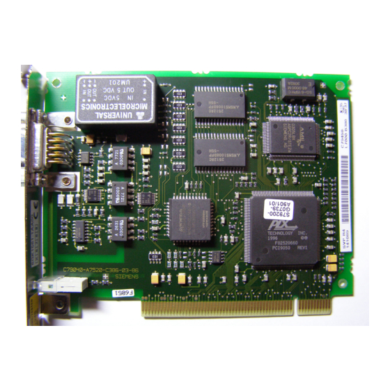
Leistung und Funktionen Die CP 5611–Baugruppe ist mit einer PROFI- BUS–Schnittstelle bis 12 MBaud ausgestattet. Sie ist für den Betrieb in PGs und PCs mit PCI–Bus- schnittstelle vorgesehen. Die zusätzlichen Schnittstellensignale für die PLC–Direktkopplung (PLC = Programmable Logic Control) werden bis 187,5 kBaud unterstützt. - Page 15 Leistung und Funktionen Hardwarevoraussetzungen Die CP 5611–Baugruppe ist eine Plug and Play (PnP)–Netzwerkkarte für Geräte mit 32 Bit PCI– Busschnittstelle die der Spezifikation PCI V2.1 entsprechen. Der Bustakt darf maximal 33 MHz betragen. Die Baugruppe hat die Abmessungen einer kurzen PCI–Baugruppe (102 mmx130 mm).
- Page 16 Leistung und Funktionen MPI/DP–Netz Mit der CP 5611–Baugruppe können bis zu 32 Geräte (PC, PG, S7–xxx oder ET 200) zu einem Netzsegment gekoppelt werden. Die physikalische Kopplung der MPI/DP–Schnitt- stelle an das MPI/DP–Netz erfolgt über ein poten- tialgetrenntes RS485–Interface, das Bestandteil der Baugruppe ist.
-
Page 17: Baugruppe Einstellen
Auch von Werkzeugen, die Sie für die Arbei- ten im Gerät benötigen, muss die elektrostati- sche Ladung abgeleitet werden. Das Stecken und Ziehen von Bauelementen und Baugruppen darf nur in stromlosem Zu- stand erfolgen. Das Gerät nicht mit geöffnetem Deckel betrei- ben. CP 5611 Installationsanleitung/Produktinformation A5E00102070–01... - Page 18 Baugruppe einstellen Memory–Adressraum Die Baugruppe belegt 2 Adressfenster mit folgen- der Größe: 128 Byte 256 KByte Der benötigte Memory–Adressraum wird durch das PnP PCI–BIOS vergeben. Interrupt Der benötigte Interrupt wird durch das PnP PCI– BIOS vergeben. CP 5611 Installationsanleitung/Produktinformation A5E00102070–01...
-
Page 19: Baugruppe Einbauen
Baugruppe einbauen Baugruppe einbauen Montage auf Steckplatz Die CP 5611–Baugruppe kann auf jedem freien PCI–Steckplatz eingebaut werden. Gerätespezifische Besonderheiten beim Betrieb von Erweiterungsbaugruppen auf PCI–Bus kön- nen Sie dem Gerätehandbuch zu Ihrem PG oder PC entnehmen. CP 5611 Installationsanleitung/Produktinformation A5E00102070–01... - Page 20 1. Schalten Sie Ihr Gerät ab, und ziehen Sie alle Leitungen an der Geräterückwand. 2. Öffnen Sie das Gerät, wie in Ihrem Geräte- handbuch beschrieben. 3. Stecken Sie die CP 5611–Baugruppe auf ei- nen der freien Steckplätze auf der Grundpla- tine. 4. Verschrauben Sie die Baugruppe an der Ge- räterückwand.
-
Page 21: Inbetriebnahme
Die Baugruppe benötigt für einen störungsfreien Betrieb 2 Speicherfenster und einen Interrupt. Diese werden vom PCI–BIOS bzw. PnP–Be- triebssystem beim Anlauf des PC/PG vergeben. Ressourcen–Konflikte Treten bei der Inbetriebnahme der Baugruppe Störungen auf, könnten folgende Ursachen vorlie- gen: CP 5611 Installationsanleitung/Produktinformation A5E00102070–01... - Page 22 Con- flict– Pci Network Con- troller as slot ..” Die vom PCI BIOS an Ändern Sie die Konfi- die Baugruppe verge- guration der betreffen- benen Ressourcen den ISA–Baugruppen. werden bereits durch nicht PnP–fähige ISA– Baugruppen belegt. CP 5611 Installationsanleitung/Produktinformation A5E00102070–01...
-
Page 23: Technische Daten
Stromaufnahme bei Nenn- max. 500 mA spannung Steckverbinder 9polige D–SUB–Buchsenleiste mit Schraubverriegelung Übertragungsart RS 485 erdfrei innerhalb der SELV– Grenzen Übertragungsgeschwindig - 9.6 kBit/s bis 12 MBit/s keit Betriebsart der MPI/DP– potentialfrei (Schnittstellensignale) erd- Schnittstelle gebunden (Leitungsschirm) CP 5611 Installationsanleitung/Produktinformation A5E00102070–01... - Page 24 Technische Daten Tabelle 6-1 , Fortsetzung Sicherheit VDE–Bestimmungen VDE 0805=EN60950 und IEC 950 UL/CSA–Zulassung Der CP 5611 erfüllt alle Anforderungen an Zusatzbaugruppen. Elektromagnetische Verträglichkeit (EMV) Störaussendung B nach EN55022=CISPR 22 Grenzwertklasse Störfestigkeit auf Signallei- +/– 2kV (nach IEC 801–5 / IEC tungen 1000–4–5, Surge)
- Page 25 Lagerung / Transport tauung) Mechanische Umgebungsbedingungen Schwingen geprüft nach DIN IEC–2–6 Betrieb 10 bis 58Hz; Amplitude 0,035 mm 58 bis 500Hz; Beschleunigung 5 m/s Schocken geprüft nach DIN IEC 68–2–27 Betrieb Halbsinus: 50 m/s (5g), 10 ms CP 5611 Installationsanleitung/Produktinformation A5E00102070–01...
- Page 26 DP–Bus. Das Steuersignal ist ’1’ aktiv, wenn die AS sendet. M5EXT M5EXT Rückleiter (GND) der Ausgang 5V–Versorgung. Die Strombela- stung durch einen externen Ver- braucher der zwischen P5EXT und M5EXT angeschlossen wird, darf max. 90 mA betragen. CP 5611 Installationsanleitung/Produktinformation A5E00102070–01...
- Page 27 24 V Versorgung lie- gen. LTG_A Signalleitung A der CP Ein–/ 5611–Baugruppe Ausgang RTS Ausgangssignal der CP Ausgang 5611–Baugruppe. Das Steuersi- gnal ist ”1” aktiv, wenn das Ge- rät (PG oder PC) sendet. Schirm auf Steckergehäuse CP 5611 Installationsanleitung/Produktinformation A5E00102070–01...
- Page 28 Technische Daten Wichtig für USA und Kanada Trägt das Gerät eines der folgenden Zeichen, liegt eine entsprechende Zulassung vor: Underwriters Laboratories (UL) nach Standard UL 1950 UL–Recognition–Mark Canadian Standard Association (CSA) nach Standard C 22.2 No 950 CP 5611 Installationsanleitung/Produktinformation A5E00102070–01...
- Page 29 Das obige SIMATIC NET–Produkt erfüllt die An- forderungen der EU–Richtlinie 89/336/EWG ”Elektromagnetische Verträglichkeit”. Die EU–Konformitätserklärung wird gemäß der obengenannten EU–Richtlinie für die zuständigen Behörden zur Verfügung gehalten bei: Siemens Aktiengesellschaft Bereich Automatisierungs– und Antriebstechnik Industrielle Kommunikation (A&D PT2) Postfach 4848 D–90327 Nürnberg CP 5611 Installationsanleitung/Produktinformation A5E00102070–01...
- Page 30 EN 50082–2 : reich 1993 1995 Aufbaurichtlinien beachten Das Produkt erfüllt die Anforderungen, wenn Sie bei Installation und Betrieb die Aufbaurichtlinien einhalten, die in folgenden Dokumentationen be- schrieben sind: PROFIBUS Netzhandbuch; Einbauanweisung im Handbuch Ihres Endgerä- tes. CP 5611 Installationsanleitung/Produktinformation A5E00102070–01...
- Page 31 Beim Betrieb der Baugruppe in einem Gerät, das diese Normen nicht erfüllt, kann die Einhaltung der entsprechenden Werte nicht garantiert wer- den. Ablagehinweis Bitte legen Sie diese Informationen zum CE–Zei- chen in Ihrem ”PROFIBUS Netzhandbuch” ab! CP 5611 Installationsanleitung/Produktinformation A5E00102070–01...
- Page 32 Technische Daten CP 5611 Installationsanleitung/Produktinformation A5E00102070–01...
- Page 33 Contents Safety-Related Notices Support and Training Performance and Func- tions SIMATIC NET Settings for the Module CP 5611 Installing the Module Installation Instructions/ Installation and Startup Product Information Technical Specifications CE Mark Release 6/2001 A5E00102070–01...
- Page 34 Sugge- stions for improvement are welcome. Siemens AG Subject to technical change. CP 5611 Installation Instructions/Product Information Bereich Automatisierungstechnik A5E00102070–01 Geschäftsgebiet Industrie-Automatisierung Postfach 4848, D- 90327 Nuremberg Siemens Aktiengesellschaft...
- Page 35 Caution indicates that minor personal injury or property damage can result if proper precautions are not taken. CP 5611 Installation Instructions/Product Information A5E00102070–01...
- Page 36 SIMATICR, SIMATIC HMIR and SIMATIC NETR are registered trademarks of SIEMENS AG. Third parties using for their own purposes any other na- mes in this document which refer to trademarks might infringe upon the rights of the trademark owners. CP 5611 Installation Instructions/Product Information A5E00102070–01...
- Page 37 Qualified persons are defi- ned as persons who are authorized to commission, to ground, and to tag circuits, equipment, and systems in accordance with established safety practices and stan- dards. CP 5611 Installation Instructions/Product Information A5E00102070–01...
- Page 38 EU Directive: Do not start up until you have established that the machine on which you intend to run this compo- nent complies with the directive 89/392/EEC. CP 5611 Installation Instructions/Product Information A5E00102070–01...
- Page 39 Siemens. Before you use the supplied sample programs or pro- grams you have written yourself, make certain that no injury to persons nor damage to equipment can result in your plant or process. CP 5611 Installation Instructions/Product Information A5E00102070–01...
- Page 40 Customer Support, Technical Support Open round the clock, worldwide: Johnson City Nuremberg Singapore SIMATIC Hotline CP 5611 Installation Instructions/Product Information A5E00102070–01...
- Page 41 E-mail: authorization@ sea.siemens.com sae.siemens.com.sg nbgm.siemens.de GMT: –5:00 GMT: +8:00 GMT: +1:00 The languages spoken on the hotlines are German and English. On the authorization hotline, French, Italian and Spanish are also available. CP 5611 Installation Instructions/Product Information A5E00102070–01...
- Page 42 Technical Support Online Services SIMATIC Customer Support provides you with a wide range of additional information on SIMATIC products in the online services: You can obtain general up-to-date information as follows: – on the Internet: address http://www.ad.siemens.de/net CP 5611 Installation Instructions/Product Information A5E00102070–01...
- Page 43 Support Mailbox) at the number +49 (911) 895-7100. To contact the mailbox, use a modem with up to V.34 (28.8 Kbauds) and the following parameter settings: 8, N, 1, ANSI, or dial with ISDN (x.75, 64 Kbps). CP 5611 Installation Instructions/Product Information A5E00102070–01...
- Page 44 Further Support If you have further questions about SIMATIC NET products, contact your local Siemens representa- tive. You will find the addresses: In our catalog IK PI on the Internet (http://www.ad.siemens.de) CP 5611 Installation Instructions/Product Information A5E00102070–01...
- Page 45 ....Technical Specifications ....CP 5611 Installation Instructions/Product Information A5E00102070–01...
-
Page 46: Performance And Functions
Performance and Functions The CP 5611 module is equipped with a PROFIBUS interface up to 12 MBaud. It is intended for use in programming devices (PGs) and PCs with a PCI bus interface. The additional interface signals for direct coupling to the PLC (programmable logic controller) are supported up to 187.5 kBaud. - Page 47 Performance and Functions Hardware Requirements The CP 5611 module is a plug and play network adapter for devices with a 32–bit PCI bus interface complying with the PCI V2.1 specification. The bus clock rate must not exceed a maximum of 33 MHz. The module has the dimensions of a short PCI module (102 mm x 130 mm).
- Page 48 Performance and Functions MPI/DP Network Using the CP 5611 module, up to 32 devices (PC, PG, S7–xxx or ET 200) can be linked to form a network segment. The physical attachment of the MPI/DP interface to the MPI/DP network is via a floating RS–485 interface integrated on the module.
-
Page 49: Settings For The Module
Make sure that you also discharge any elec- trostatic charge from tools you intend to use. Components and modules must only be in- serted or removed when the power supply is off. Do not operate the unit with the housing open. CP 5611 Installation Instructions/Product Information A5E00102070–01... - Page 50 The module occupies two address windows with the following size: 128 bytes 256 Kbytes The required memory address range is assigned by the PnP PCI–BIOS. Interrupt The required interrupt is assigned by the PnP PCI–BIOS. CP 5611 Installation Instructions/Product Information A5E00102070–01...
-
Page 51: Installing The Module
Installing the Module Installing the Module Installing in a Slot The CP 5611 module can be installed in any free PCI slot. Read the sections in the manual of your PG or PC relating to the operation of expansion modules on the PCI bus. - Page 52 2. Open the device as described in the corres- ponding manual. 3. Insert the CP 5611 module in a free slot on the motherboard. 4. Screw the module to the rear wall of the de- vice.
-
Page 53: Installation And Startup
Installation and Startup Requirements for Problem–Free Operation To operate correctly, the module requires two memory windows and an interrupt. These are assigned by the PCI–BIOS or by the PnP operating system during startup of the PC/PG. CP 5611 Installation Instructions/Product Information A5E00102070–01... - Page 54 Controller as slot ..” The resources assi- Change the configura- gned to the module by tion of the ISA module the PCI BIOS are al- involved. ready being used by non–plug and play ISA modules. CP 5611 Installation Instructions/Product Information A5E00102070–01...
-
Page 55: Technical Specifications
9-pin sub D female connector with screw locking mechanism. Type of transmission RS 485 floating within the SELV limits Transmission rate 9.6 Kbps to 12 Mbps Mode on the MPI/DP inter- Floating (interface signals) non–floating face (cable shield) CP 5611 Installation Instructions/Product Information A5E00102070–01... - Page 56 Technical Specifications Tabelle 6-1 , continued Safety VDE regulations VDE 0805=EN60950 and IEC 950 UL/CSA approval The CP 5611 meets all requirements for additional modules. Electromagnetic Compatibility (EMC) Noise emission B complying with EN55022=CISPR Limit class Noise immunity on signal li- +/–...
- Page 57 Vibration Tested to DIN IEC-2-6) Operation 10 to 58 Hz; amplitude 0.035 mm 58 to 500 Hz; acceleration 5 m/s Shock Tested to DIN IEC 68–2–27 Operation Half sine: 50 m/s (5g), 10 ms CP 5611 Installation Instructions/Product Information A5E00102070–01...
- Page 58 Pin 2 is not connected With other – MPI/DP components, the return wire of the floating 24 V power supply can be applied to this pin. LTG_B Signal line B of the CP 5611 mo- Input/ dule output RTSAS RTSAS, input signal for MPI/DP Input bus.
- Page 59 NC (P24V) Pin 7 is not connected With other – MPI/DP components, the P24V pin of the 24 V floating power supply can be applied to this pin. LTG_A Signal line A of the CP 5611 mo- Input/ dule output RTS output signal of the CP 5611 Output module.
- Page 60 If the device has one of the following marks, the corresponding approval has been obtained: Underwriters Laboratories (UL) complying with Standard UL 1950 UL Recognition Mark Canadian Standard Association (CSA) complying with Standard C 22.2 No 950 CP 5611 Installation Instructions/Product Information A5E00102070–01...
- Page 61 The EU conformity certificate is available for the relevant authorities according to the above EU directive and is kept at the following address: Siemens Aktiengesellschaft Bereich Automatisierungs- und Antriebstechnik Industrielle Kommunikation (A&D PT2) Postfach 4848 D-90327 Nürnberg CP 5611 Installation Instructions/Product Information A5E00102070–01...
- Page 62 Installation Guidelines The product meets the requirements providing you adhere to the guidelines for installation and operation described in the following documentation: PROFIBUS Network Manual; Installation instructions in the manual of your target device. CP 5611 Installation Instructions/Product Information A5E00102070–01...
- Page 63 Filing the Information Please file this information on the CE mark in your “PROFIBUS Network Manual”! CP 5611 Installation Instructions/Product Information A5E00102070–01...
- Page 64 Technical Specifications CP 5611 Installation Instructions/Product Information A5E00102070–01...
Need help?
Do you have a question about the CP 5611 and is the answer not in the manual?
Questions and answers