Advertisement
Advertisement
Table of Contents

Related Manuals for MOTECK CIS1


Summary of Contents for MOTECK CIS1
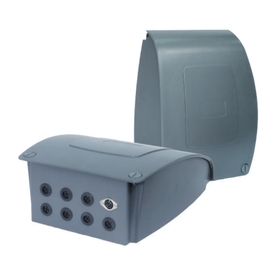
- Page 1 USER GUIDE www.moteck.com CIS1 Control Box Specification - Input voltage: 24V DC - Output voltage: 24V DC - Max. current: 7.5A per channel - Max. number of actuators: 2 channels - Duty cycle: 10%, max. 2 min. continuous operation in 20 min.
- Page 2 Connection Diagram PCBA: Actuator UP Actuator Down External switch 24V DC IN Actuator 1 Actuator 2 Actuator: 1. With reed sensor feedback (example of ID10S actuator) Signal Power 1 2 3 4 5 Definition DATA Wires color Yellow White Black 2.
- Page 3 Moteck sales staff to provide further services. Electrical Installation: 1. Open the lid of the CIS1 control box, thread the cables of actuator 1 and actuator 2 through the hole in the control box, and lock them to the terminal according to the wire sequence described on the previous page.
- Page 4 The LED will flash quickly to confirm the position is saved. 4. Drive both actuators toward the memorized position 1. 5. Drive both actuators toward the memorized position 2. 6. Drive both actuators toward the memorized position 3. ©2020 Apr. MOTECK. MO-I-0040 Version: 2.0...
Need help?
Do you have a question about the CIS1 and is the answer not in the manual?
Questions and answers