Panduit ATLONA OmniStream AT-OMNI-521 Manual
R-type single-channel networked av decoder
Hide thumbs
Also See for ATLONA OmniStream AT-OMNI-521:
- Manual (147 pages) ,
- Installation manual (13 pages) ,
- Manual (68 pages)

Related Manuals for Panduit ATLONA OmniStream AT-OMNI-521


Summary of Contents for Panduit ATLONA OmniStream AT-OMNI-521
- Page 1 OmniStream R-Type ™ Single-Channel Networked AV Decoder Atlona Manuals AT-OMNI-521 Networked AV...
- Page 2 Version Information Version Release Date Notes Mar 2018 Initial release Jul 2018 Includes updates to 1.2.1 firmware; AMS updates Nov 2018 1.2.2 firmware; Dolby Vision decoding/licensing, fast switching Aug 2019 Documentation updated to support AMS 2.4.0 Sep 2019 Documentation updated to support OmniStream 1.2.5; various bug fixes and added Portrait Mode (page 43) for Video Walls.
- Page 3 Welcome to Atlona! Thank you for purchasing this Atlona product. We hope you enjoy it and will take a extra few moments to register your new purchase. Registration only takes a few minutes and protects this product against theft or loss. In addition, you will receive notifications of product updates and firmware.
- Page 4 Atlona, Inc. (“Atlona”) Limited Product Warranty Coverage Atlona warrants its products will substantially perform to their published specifications and will be free from defects in materials and workmanship under normal use, conditions and service. Under its Limited Product Warranty, Atlona, at its sole discretion, will either: •...
- Page 5 Atlona, Inc. (“Atlona”) Limited Product Warranty • Damage, deterioration or malfunction resulting from the installation or removal of this product from any installation, any unauthorized tampering with this product, any repairs attempted by anyone unauthorized by Atlona to make such repairs, or any other cause which does not relate directly to a defect in materials and/or workmanship of this product.
- Page 6 Important Safety Information 9. Do not defeat the safety purpose of a polarized CAUTION or grounding-type plug. A polarized plug has two RISK OF ELECTRIC SHOCK blades with one wider than the other. A grounding DO NOT OPEN type plug has two blades and a third grounding CAUTION: TO REDUCT THE RISK OF prong.
-
Page 7: Table Of Contents
Table of Contents Introduction Features Package Contents Panel Description Installation RS-232 Connections IR Connections Connection Instructions Connection Diagram Configuration Accessing Decoders in AMS Configuring a Static IP Address Basic Operation LED Indicators ID Button Broadcast Messaging Reset to Factory-Default Settings. Rebooting OmniStream Unicast Mode Multicast Mode... - Page 8 Table of Contents Web Server Accessing the Web Server Getting the IP Address Logging In System information page SAP page IP Input page Serial page HDMI Output page Logo page Text page Network page PTP page LLDP page Configuration page Users page License page Upgrade page...
-
Page 9: Introduction
Introduction The Atlona OmniStream™ 521 (AT-OMNI-521) is a networked AV decoder for an OmniStream-encoded video stream up to UHD @ 60 Hz and HDR, plus embedded audio and RS-232 or IR control pass-through. It is part of the OmniStream R-Type Series, designed for high performance, flexible distribution of AV over Gigabit Ethernet in residential and commercial applications. -
Page 10: Panel Description
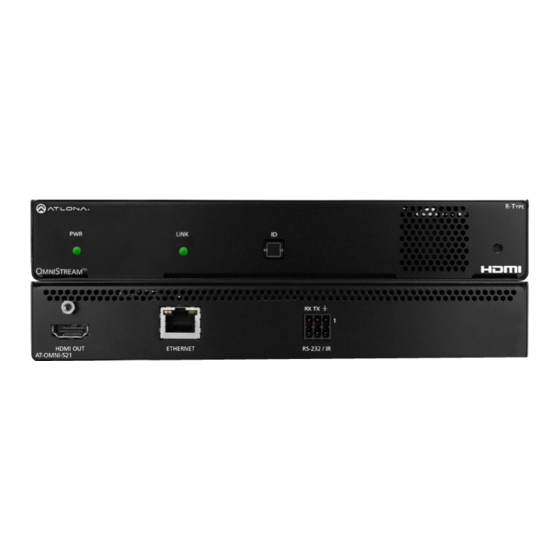
Panel Description LINK LINK TREAM Front TREAM RX TX RX TX HDMI OUT ETHERNET RS-232 / IR AT-OMNI-521 HDMI OUT ETHERNET RS-232 / IR AT-OMNI-521 Rear HDMI OUT This LED indicator glows bright green when the unit Connect an HDMI cable from this port to a UHD/HD is powered. -
Page 11: Installation
Installation RS-232 Connections The AT-OMNI-521 provides RS-232 over IP which allows communication between an automation system and an RS- 232 device. This step is optional. Either the top three or bottom three set of terminals can be used for RS-232. 1. -
Page 12: Ir Connections
Installation IR Connections The same port that provides RS-232 connections also supports bidirectional IR pass-through, allowing a device to be controlled from either the headend or the decoder endpoint. This step is optional. Either the top three or bottom three set of terminals can be used for IR. Only the RS-232 2 port (bottom set of connectors) supports both RS-232 and IR. - Page 13 Installation For downstream IR control, either multicast or unicast mode can be used. However, when controlling a source from the decoder (viewing location), unicast mode should be used. Refer to Unicast Mode (page 22) Multicast Mode (page 24) for more information. Refer to IR Control (page 34) for information on IR configuration within AMS.
-
Page 14: Connection Instructions
Installation Connection Instructions 1. Connect an Ethernet cable from the ETHERNET port on the decoder to a PoE-capable switch on the Local Area Network (LAN). IMPORTANT: If a PoE-capable switch is not available, a PoE injector (purchased separately) must be used. 2. -
Page 15: Connection Diagram
Installation Connection Diagram Blu-ray Player Automation Control System CT OR RE SE 48 V M NI AT-OMNI-512 Projector AT-OMNI-521 M NI AT-OMNI-521... -
Page 16: Configuration
Configuration Accessing Decoders in AMS It is recommended that the Atlona Management System (AMS) be used to configure and control OmniStream devices. AMS uses multicast Domain Name Server (mDNS) to automatically discover each encoder on the network. AMS is free and can be downloaded from https://www.atlona.com/ams. By default, the AT-OMNI-521 is set to DHCP mode, allowing a DHCP server (if present) to assign the encoder an IP address. - Page 17 Configuration 6. Click Devices from the fly-out menu. 7. Click the Unassigned option. 8. Click the left and right arrows, at the bottom of the Unassigned list, to scroll through all available devices. Arrow buttons AT-OMNI-521...
- Page 18 Configuration All available decoders will be displayed under the Unassigned category. When a decoder is unassigned, it means that it has not been assigned to a site, building, and/or room. Refer to the AMS User Manual for more information on these topics. If a DHCP server is not found within 60 seconds, the encoder will be placed in Auto IP mode and assigned an IP address within the range of 169.254.xxx.xxx.
-
Page 19: Configuring A Static Ip Address
Configuration Configuring a Static IP Address The following section is only required to set the AT-OMNI-521 decoder, currently in Auto IP mode, to a static IP address. If a DHCP server is not found within 60 seconds, decoders are automatically placed in Auto IP mode and will be assigned an IP address within the range 169.254.xxx.xxx. -
Page 20: Basic Operation
Basic Operation LED Indicators The following table provides a listing of front-panel LED indicators and their status: Description Unit is powered off. • If using a PoE switch, make sure that the port on the switch that is connected to the decoder, has PoE enabled. When the decoder is powered using PoE, the PWR indicator will be green. -
Page 21: Id Button
Basic Operation ID Button The ID button serves two functions: 1. Sends a broadcast message, over the network, to any devices that may be listening. 2. Resets the decoder to factory-default settings. LINK TREAM RX TX Broadcast Messaging Press and release the ID button to send a broadcast notification over the network to any devices that may be listening. -
Page 22: Unicast Mode
Basic Operation Unicast Mode The term unicast is used to describe a configuration where information is sent from an encoder to a single decoder. Although it is common to have multiple encoder and decoder units within a system, it may also be desirable to restrict a single encoder to communicate with one decoder. - Page 23 Basic Operation 6. Go to the decoder AMS interface. 7. Click IP INPUT from the menu. 8. Remove the IP address from the Multicast Address field. 9. Click the SAVE button to commit changes. Field should be blank 10. Unicast setup is complete. The decoder unit will now receive streams exclusively from the encoder containing the IP address of this decoder.
-
Page 24: Multicast Mode
Basic Operation Multicast Mode The term multicast is used to describe a configuration where information is sent from one or more points to a set of other points. For example, a single encoder can transmit data to multiple decoders. In addition, if multiple encoders are used, each encoder can stream data to any decoder that is not already receiving data from an encoder. - Page 25 Basic Operation AT-OMNI-521...
- Page 26 Basic Operation 5. Enter the desired scrambling key using one of the following methods: • Manual enter a user-defined key in the Key field. • Click the icon to generate a random key using AMS. Each time this icon is clicked, a new scrambling key will be generated.
-
Page 27: Slate / Logo Insertion
Basic Operation Slate / Logo Insertion IMPORTANT: Slate / logo insertion is not supported when fast switching is enabled. Refer to Fast Switching (page 32) for more information on enabling and disabling fast switching. Slate / logo insertion is managed from within AMS. The difference between a “slate” and “logo” is in the size of the image and how it is used: Logos are classified as smaller, low-resolution images that can be positioned at specified locations on the screen. - Page 28 Basic Operation 7. A new window group will be created with the name of the logo that was provided in Step 4. Image window group 8. Perform one of the following: • If the selected image will be used as a logo, then proceed with Steps 9 through 13. •...
- Page 29 Basic Operation 10. Click the Aspect Ratio drop-down list to set the aspect ratio of the image. Selecting Keep will maintain the aspect ratio. Select Stretch to scale the image to fill the screen. 11. Enter the location of the on-screen image, in pixel values, by entering the desired values in the Horizontal and Vertical fields.
-
Page 30: Text Insertion
Basic Operation Text Insertion Text can be inserted and scrolled across the screen, making it useful for messages and notifications. Several options are available when using text: Scroll speed adjustment (forward, reverse, or static), number of iterations, text color, vertical / horizontal position, as well as transparency. 1. - Page 31 Basic Operation 9. Specify the size of the text in the Width (%) and Height (%) fields. Each of these values is based on the horizontal and vertical resolution of the screen. 10. Click the SAVE button to apply all changes. AT-OMNI-521...
-
Page 32: Fast Switching
Basic Operation Fast Switching IMPORTANT: If Fast Switching is enabled, latency increases from 0.5 frames to 1.5 frames. When using Fast Switching mode, the output resolution will be 1920x1080p, regardless of the source resolution. Also note that 1080i is not supported in Fast Switching mode. Also note that Slate / Logo Insertion and Text Insertion will be automatically disabled when Fast Switching is enabled. -
Page 33: Advanced Operation
Advanced Operation AES67 Audio AES67 audio is a standard for high-performance audio streaming over IP, providing several features such as synchronization, media clock identification, and connection management. AES67 does not support bitstream/ compressed audio formats, such as Dolby® Digital, and others. Source audio must be transmitted as LPCM up to eight channels at 192 kHz / 24-bit. -
Page 34: Ir Control
Advanced Operation IR Control OmniStream provides IR control from either the headend / source location to the displays (downstream) or from the viewing location to the headend (upstream). For downstream IR control, either multicast or unicast mode can be used. However, when controlling a source from the viewing location, unicast mode should be used. Refer to Unicast Mode (page 22) Multicast Mode (page 24) -
Page 35: Upstream Ir Control
Advanced Operation Upstream IR Control In order to send IR data upstream, from the decoder to the encoder, a few additional simple steps are required. 1. Follow steps 1 through 9, under Downstream IR Control (page 34). 2. Click IP Input in the top menu bar. 3. -
Page 36: Scrambling
Advanced Operation Scrambling OmniStream supports 128-bit Advanced Encryption Standard (AES) scrambling and is required for HDCP-encrypted streams. Scrambling can be enabled or disabled through AMS, and can be applied to individual sessions. In order for scrambling to function properly, it must be enabled on both the encoder session and all decoders subscribed to a stream that is a part of a scrambled session. -
Page 37: Using The Virtual Matrix
Advanced Operation 3. Enter the desired scrambling key in the Key field. NOTE: If a user-defined key is specified, then it must be a minimum of eight alphanumeric characters. Special characters and spaces are not permitted. 4. Click the Save button at the bottom of the page to commit the changes. Using the Virtual Matrix 1. -
Page 38: Creating Video Walls
Advanced Operation Creating Video Walls NOTE: OmniStream video walls do not support 1080i sources. The following table lists the maximum video wall size, based on the resolution of the source. Resolution Maximum Video Wall Size 4Kp60 2 x 2 4Kp30 16 x 16 1080p60 n x n (no limit) - Page 39 Advanced Operation Note that the order in which each image is cropped, scaled, and/or rotated is arbitrary. In this example, the configuration process will begin with Display 1, in the top left. 1. Login to AMS. Refer to Accessing Decoders in AMS (page 16) if necessary.
- Page 40 Advanced Operation 6. Click the Enable toggle to activate the Video wall option. Once enabled, the Video wall section will be expanded and display all available options. 7. Click the Unit drop-down list to select the unit of measure. In this example, Pixels (the default value) will be used.
- Page 41 Advanced Operation 10. Click the Rotation drop-down list to select the rotation angle of the image. In this example, select 180 from the drop-down list. The image will be flipped, vertically. This step is only applied when configuring the two top displays.
- Page 42 Advanced Operation Once all four decoders have been properly configured, the video wall should appear similar to the following: Encoder Decoder AV LAN Decoder Decoder Decoder Display Wall 13. Check the image, on each display, and make sure they are aligned correctly with the other images on the video wall.
-
Page 43: Portrait Mode
Advanced Operation Portrait Mode Images can be rotated 90° or 270° to create portrait-oriented video walls. The steps to configure portrait-oriented video walls is very similar to creating landscape video walls. A similar scenario to the landscape video wall challenge will be used to illustrate how to configure a 1 x 4 portrait- oriented video wall. - Page 44 Advanced Operation 1. Access the built-in web server for the OmniStream decoder and login using the required username and password. The default credentials are listed below: Username: admin Password: Atlona 2. Click HDMI OUTPUT in the menu bar. 3. Locate the Resolution option, in the Video section and select 1920x1080. This will scale the output resolution to 1920x1080.
- Page 45 Advanced Operation 4. Click the Stretch/Crop Mode drop-down list and select Full Screen. This guarantees that the image will fill the screen. 5. Under the Video Wall section, click the Enable toggle to activate the Video wall option. Once enabled, the Video wall section will be expanded and display all available options.
- Page 46 Advanced Operation Source resolution Width (pixels) Height (pixels) 3840 x 2160 (UHD) 1920 1080 1920 x 1080 (1080p) 8. Enter the number of video wall rows in the Horizontal field and the number of columns in the Vertical field. These values are the pixel start position (upper left most pixel). The table below, lists left and right coordinates for a 1x4 video wall, with the specified source resolution.
- Page 47 Advanced Operation Figure 2.2: Portait-mode 1 x 4 video wall with Display 1 properly oriented. Encoder Decoder Decoder Decoder Decoder Display Wall 10. Click the SAVE button at the bottom of the screen to commit changes. 11. Repeat steps 3 through 9 for decoders 2, 3, and 4. Since display 2 and 3 were mounted upside-down, they will require a rotation of 180°...
- Page 48 Advanced Operation Figure 2.3: Portait-mode 1 x 4 video wall displayed correctly. Encoder Decoder Decoder Decoder Decoder Display Wall AT-OMNI-521...
-
Page 49: Bezel Compensation
Advanced Operation Bezel Compensation Displays have a region where video is not displayed, called the bezel. This can cause display issues when creating video walls. Bezel compensation takes this area into account when a single video source is mapped across multiple displays. - Page 50 Advanced Operation If two bezels need compensating (e.g. on a 3x3 wall, where the middle display has two bezels is in the way, in each direction), use the following formula: Total width (px) Bezel width (px) = x bezel width (in/mm) [ display area width (in/mm) + bezel width #1 (in/mm) + bezel width #2 (in/mm) ] 3.
-
Page 51: Video Walls Using Velocity
Advanced Operation Video Walls using Velocity The following section provides instructions on creating and using video walls with the Atlona Velocity Control Software. Familiarity with the Velocity software is assumed. Refer to the Atlona Velocity User Manual for more information, if necessary. NOTE: As of this writing, the Velocity™... - Page 52 Advanced Operation 8. The Modify Room screen will be displayed. Click the Add Technology icon in the top far-right corner of the screen. This icon is represented by the + sign. 9. The Technology fly-out menu will be display. 10. In the fly-out menu, click Miscellaneous > Atlona > to expand the Atlona technology menu. 11.
- Page 53 Advanced Operation 12. Scroll down to the bottom of the page and locate the Velocity Video Wall driver. 13. Click the Edit icon. This icon is represented by a pencil. 14. The Video Wall / Pixel Space Dimensions dialog will be displayed.
- Page 54 Advanced Operation c. To create a custom size for the video wall, enter the desired dimensions under the Custom section. Enter the width and height directly, or use the spinner controls at the far end of each field, to adjust the values.
- Page 55 Advanced Operation a. Pixel Space Save Click this icon to display the VideoWall dialog box, Click this icon to save the current layout/settings. allowing modification of both the Video Wall and Click the down-arrow, next to this icon, to display Pixel Space settings.
- Page 56 Advanced Operation 17. Click the Auto Arrange icon in menu bar at the top of the Pixel Space window. Move the mouse within the Auto Arrange pop-up dialog to adjust the size of the video wall. Click the lower right-most blue square of the video wall to commit the selection.
- Page 57 Advanced Operation 18. Click the Lock Displays icon in the menu bar of the Pixel Space window. This is optional. However, enabling this feature will prevent accidental repositioning of the displays, during the configuration procedure. When locked, this icon will turn red. Both the Trash and Auto Arrange icons will be disabled. To unlock the displays (for adjustment purposes), click the Lock Displays icon again.
-
Page 58: Creating Presets
Advanced Operation Creating Presets Presets are used to save window layouts, within the Pixel Space window. Once a preset is created it can be recalled at any time. 1. Click the Presets icon. When clicked, this icon will turn green and the Presets window will be displayed on the left side of the screen. - Page 59 Advanced Operation 3. Enter than name of the preset in the Preset Edit dialog. 4. Click the CLOSE button to save the preset name and dismiss the dialog. 5. Under the Sources window, on the left side of the screen, drag and drop the desired source(s) to each display in the Pixel Space window.
- Page 60 Advanced Operation Preset Orientation There may be some situations in which content that is spread across multiple displays must be rotated. Two examples are shown below. Example 1: Content requiring rotation. In the following example, a single source is spread across three vertical displays. The source content (shown on the left) is rotated -90 degrees.
- Page 61 Advanced Operation Example 2: Content that does not require rotation. In this example, three sources are spread across three vertical displays. The content (shown on the left) was created to be displayed horizontally. In this case, rotating the source is not required. Figure 1.1 - Source content Figure 1.2 - Source content properly rotated to span three vertically rotated displays.
- Page 62 Advanced Operation Sources can also be re-sized “on the fly” to achieve the desired presentation. Refer to the illustration below. To re-size a source, click and drag the source window horizontally, vertically, or diagonally. Release the mouse to commit the changes. Refer to the Atlona Velocity User Manual for more information on manipulating source windows.
-
Page 63: Creating And Using Drop Zones
Advanced Operation Creating and Using Drop Zones Drop Zones are “containers”, allowing sources to be placed (“dropped”) in real-time on a video wall. Drop Zones are similar to presets, except that unlike presets, Drop Zone content can be changed on-the-fly within the Video Wall Control Screen. - Page 64 Advanced Operation Preset Orientation There may be some situations in which content that is spread across multiple displays must be rotated. Two examples are shown below. Example 1: Content requiring rotation. In the following example, a single source is spread across three vertical displays. The source content (shown on the left) is rotated -90 degrees.
- Page 65 Advanced Operation Example 2: Content that does not require rotation. In this example, three sources are spread across three vertical displays. The content (shown on the left) was created to be displayed horizontally. In this case, rotating the source is not required. Figure 1.1 - Source content Figure 1.2 - Source content properly rotated to span three vertically rotated displays.
- Page 66 Advanced Operation 7. Click ADD, under the Zones window. 8. Click EDIT and provide a name for the Zone, in the Edit Zone dialog box. Click Close to save the change. Note that each time the ADD button is clicked, a new Drop Zone container is created. In this first example, two Drop Zone containers are created.
- Page 67 Advanced Operation 9. Drag each container to the desired area on the video wall. To place a container on each device, left-click and drag, then release when a majority of the window is placed over the device. If a container is positioned over the intersection of two windows, then it will automatically be resized to accommodate both devices, as shown below.
- Page 68 Advanced Operation 11. Repeat the above steps to create additional Drop Zone presets. Each Drop Zone preset can have a different number of containers. However, the number of containers that are created should not exceed the number of devices within the Pixel Space window. 12.
- Page 69 Advanced Operation 16. The Presets portion of the control screen will be displayed. All presets that were created, will be listed on the left-hand side of the screen, as shown below. Note in this example, only one preset was created. Click the desired preset to recall it.
- Page 70 Advanced Operation The first Drop Zone will can dynamically apply sources to the preset, which is a 2x2 video wall, to the top-left, bottom-left, and both or only one display(s) on the right-hand side. Some possible combinations are shown below. Drop Zone containers have been labeled alphabetically, for reference. Note that although the top-right and bottom-right displays are physically separate, dragging and dropping a source from the left-hand side of the screen to Drop Zone container “C”, will “map”...
-
Page 71: Custom Drop Zones
Advanced Operation Custom Drop Zones In addition to creating user-defined Drop Zones, the Velocity Video Wall also includes a Custom Drop Zone. This unique type of Drop Zone allows dynamic re-sizing of sources to be mapped across any of the decoders. 1. - Page 72 Advanced Operation 5. Close the Video Wall Configuration screen and then click the Launch Control icon on the Modify Room screen. 6. Click the VIDEO WALL icon to enter video wall control screen. 7. Click Zones at the bottom of the screen, then click the Custom Drop Zone icon. Custom Drop Zone 8.
- Page 73 Advanced Operation 9. Resize or reposition windows by clicking and dragging the edges of each source, horizontally / vertically, to the desired area of a container. To reposition the source to a different container(s), click in the middle of a source, then drag and drop to the desired container(s).
-
Page 74: The Ams Interface
The AMS Interface Device Info page The Device Info page provides general information about the decoder. The encoder has an identical interface. Alias Enter a name for the unit in this field. This is optional. Model The model number of the unit. IP Address Displays the IP address of the decoder. - Page 75 The AMS Interface Uptime Time elapsed since the last reboot operation. Hostname The hostname of this unit. This can be changed if desired. By default, the host name is automatically created using the model of the unit and adding the last five digits of the unit serial number. FACTORY RESET Click this button to reset the encoder to factory-default settings.
- Page 76 The AMS Interface Dolby Vision License Enabled This indicator will be green if the Dolby Vision license is installed. Dolby Vision License Key Enter the license key in this field, then press the SAVE LICENSE button. SAVE LICENSE Click this button to activate a valid Dolby License key. NTP Server Specify the desired NTP server in this field.
-
Page 77: Ip Input Page
The AMS Interface IP Input page The IP Input tab provides configuration of each input, the assigned multicast address(es), and ports. Enabled Click this checkbox to enable the IP input. Interface The physical interface that will be used to carry the multicast traffic. The only available selection is eth1. Multicast Address Enter the multicast address of the decoder stream. - Page 78 The AMS Interface Advanced Settings The following settings are related to IGMPv3 multicast filtering. IGMPv3 provides support for source-specific multicast devices. For example, the receiver of a multicast group can specify a set of addresses to which it can subscribe (include mode) or not subscribe (exclude mode). Mode (IGMPv3 only) Click this drop-down list to select the mode.
-
Page 79: Hdmi Output Page
The AMS Interface HDMI Output page The HDMI Output tab provides options to configure the output streams. Enabled Click this toggle switch to enable or disable scrambling on the decoder. When enabled, the toggle switch will be green. Enter the scrambling key in this field. The scrambling key must be ASCII and must contain a minimum of eight characters. - Page 80 The AMS Interface Video Click this drop-down list to select the desired primary video input. Select generator to use the internal signal generator. Select the Not Used option to leave the video input unassigned. Status Displays the input status. If no input is active or detected, then this field will display “No active video”. Stretch / Crop Mode Click this drop-down list to select the aspect ratio.
- Page 81 The AMS Interface Downmixing Click this drop-down list to select how LPCM audio will be down-mixed. Note that lossless audio formats cannot be down-mixed. Type Description None Audio is not down-mixed. Stereo Audio is down-mixed to two-channel stereo. Auto Display is always on, source audio/video signal switches on/off Status Displays the audio input status.
- Page 82 The AMS Interface Projector Cooldown (s) Enter the time interval, in seconds, before the projector can be powered-off. This time interval prevents the decoder from sending additional commands until the projector has had time to complete its cool-down process. Standby Timeout Enter the time interval, in seconds, before the next command can be accepted by the display.
-
Page 83: Serial Page
The AMS Interface Serial page The Serial page provides serial port configuration when using control signals. Supported Modes Lists the supported protocols. Mode Click this drop-down list to select the desired serial mode: Infrared or Serial. Baud Rate Click this drop-down list to select the desired baud rate. Data Click this drop-down list to select the number of data bits. - Page 84 The AMS Interface Port Click this drop-down list to select the port: serial_port1, serial_port2, or Not Used. Mode Click this drop-down list to select the desired control mode. Interface Description Displays the command-line interface of the decoder. output Serial port will send commands directly to the display device. tcpproxy Commands are sent over IP but triggered over the serial port.
-
Page 85: Network Page
The AMS Interface Network page The Network page provides the ability to enable or disable DHCP mode for the physical interface. When DHCP mode is disabled, the IP address, subnet mask, and gateway must be provided. This screen is identical to the Network page for the encoder. - Page 86 The AMS Interface Advanced Settings Click the SHOW ADVANCED button to view the following options. Link Speed Displays the port speed in Mbps. MAC Address The MAC address of the Ethernet channel. Telnet Authentication Click this toggle switch to enable or disable Telnet authentication. If enabled, then the toggle switch will be green. Once enbled, connecting to the encoder using Telnet will require login credentials.
-
Page 87: Other Page
The AMS Interface Other page The Other page provides logo/slate, text, and PTP management. Click the menu in the upper-left corner of the AMS screen to switch between Logo, Text, PTP, and SAP screens. Logo The Logo page provides the ability to upload a custom logo. This logo will be displayed when no video signal is detected. -
Page 88: Text
The AMS Interface Vertical Enter the vertical position of the logo on the screen. Height Enter the horizontal resolution of the logo, in pixels. Width Enter the vertical resolution of the logo, in pixels. IMPORTANT: Maximum logo resolution (both height and width) is 1/4 of the video resolution. Text The Text page provides the ability to display scrolling or stationary text superimposed on the source image. -
Page 89: Ptp
The AMS Interface Horizontal (%), Vertical (%) Specify the location of the text in the Horizontal (%) and Vertical (%) fields. Each of these values is based on the horizontal and vertical resolution of the screen. Width (%), Height (%) Specify the size of the text in the Width (%) and Height (%) fields. -
Page 90: Sap
The AMS Interface Domain Number Enter the domain number in this field. Valid entries are 0 through 127. Priority 1 Enter the priority number in this field. Priority 2 Enter the priority number in this field. Is GM Present This indicator displays the existence of a grandmaster clock for the specified PTP domain number. If the indicator is green, then the grandmaster clock exists on this interface. -
Page 91: The Virtual Matrix
The AMS Interface The Virtual Matrix 1. In AMS, click Devices from the fly-out menu. 2. Click the OmniStream option. 3. Click Virtual Matrix. 4. The OmniStream Virtual Matrix page will be displayed. AT-OMNI-521... -
Page 92: Layout And Operation
The AMS Interface Layout and Operation The illustration below, shows a multiple OmniStream units (encoders and decoders). The Virtual Matrix is organized into rows and columns. The blue circle with the checkmark indicates that these two OmniStream units are connected to one another. The third column shows an OmniStream R-Type decoder (AT-OMNI-521). - Page 93 The AMS Interface When these icons are clicked, the associated icons will be displayed in the rows and columns of the Virtual Matrix. Symbol Description Video only Audio only Data only Connected; not all signals are active Connected; all streams are being used Video stream Audio stream Data stream...
-
Page 94: Web Server
Web Server Accessing the Web Server In order to access the web server of the desired encoder/decoder, the IP address of the encoder must be known. This can be accomplished by more than one method. Running IP scanner software or using the Address Resolution Protocol (ARP) are two possibilities. -
Page 95: Logging In
Web Server 4. At the command prompt, type arp -a. Make sure to include a space between arp and the -a argument, then press [ENTER]. 5. Press [ENTER]. Several lines of information will be displayed. Locate the MAC address of the encoder/decoder, under the Physical Address column. - Page 96 Web Server 3. The System Information page will be displayed. 4. The login process is complete. AT-OMNI-521...
-
Page 97: System Information Page
Web Server System information page Firmware version The version of firmware that the encoder is running. Always make sure the latest version of firmware is installed. Model The model number of the unit. Description Provides the option of assigning descriptive name to the unit. - Page 98 Web Server System Temperature Displays the ambient enlosure temperature. Die Temperature Displays the value returned from the die temperature sensor (DTS) on the chip of the PCB. Power Consumption Displays the precise power consumption of the encoder. Hostname Displays the hostname of the encoder. By default, OmniStream decoders are assigned a default hostname, which is constructed as follows: at-omni-[SKU]-[last five digits of MAC address].
-
Page 99: Sap Page
Web Server SAP page Enable Click this toggle switch to enable or disable SAP (Session Announcement Protocol). SAP is enabled by default. SAVE Click this button to commit changes. AT-OMNI-521... -
Page 100: Ip Input Page
Web Server IP Input page Input window groups The following fields apply to all Input window groups. Name Multicast filter (IGMPv3) > Addresses The name of the input. This field cannot be changed. Enter the desired address(es) in this field. Separate multiple multicast IP addresses with a comma delimiter. -
Page 101: Serial Page
Web Server Serial page Serial port configuration window groups The following fields apply to both Serial port configuration window groups. Name The name of the serial port. This field cannot be changed. Supported Modes Displays the supported protocols for the serial port. This field cannot be changed. Mode Click this drop-down list to select the desired serial mode. - Page 102 Web Server Flow Control Click this drop-down list to select the type of flow control: none, xonxoff, or hw. Port Click this drop-down list to select the desired serial port: Serial Port 1 or Serial Port 2. SAVE Click this button to commit all changes within the Serial port configuration window group. Serial configuration window groups The following fields apply to both Serial configuration window groups.
-
Page 103: Hdmi Output Page
Web Server HDMI Output page Output window group Name The name of the output port. This field cannot be changed. Enable Click this toggle switch to enable or disable scrambling. If a scrambling key is used on the subscribed encoder, then descrambling must be enabled on the decoder in order for the source signal to reach the sink device. - Page 104 Web Server Input Click this drop-down list to select the desired IP input. Available options are ip_input1 - ip_input5, none, and generator. Input status Displays the input status. If no video stream is detected, then “No active video” will be displayed. Status Displays the active video input.
- Page 105 Web Server Video Wall Click this toggle switch to enable or disable the video wall option. Refer to Creating Video Walls (page 38) more information on using video walls. Fast Switching Click this toggle switch to enable or disable fast- switching.
- Page 106 Web Server Type Click this drop-down list to select the display mode. Type Description DispSW AVon Display switches on/off, source audio/video signal always on. DispSW AVSW Display switches on/off, source audio/video signal switches on/off. AV SW Display is always on, source audio/video signal switches on/off Always on Display is always on, source audio/video signal always on.
-
Page 107: Logo Page
Web Server Logo page New logo window group Name Enter a name for the logo in this field. Choose File Click this button to select the logo file to be uploaded. Files must be in .png format and must not exceed 5 MB (5120000 bytes) in size. - Page 108 Web Server Vertical (%) Enter the vertical position of the logo on the screen. This value is based on the total vertical resolution of the screen. Width (%) Enter the width of the logo. This value is based on the total horizontal resolution of the screen.
-
Page 109: Text Page
Web Server Text page Text insertion window groups Target Displays the name of the output where the text will appear. This field cannot be changed. Enable Click this toggle switch to enable or disable the text. When the toggle switch is orange, the text will be enabled. Text Enter the desired text in this field. - Page 110 Web Server Horizontal Enter the horizontal position of the text in this field. Vertical Enter the vertical position of the text in this field. Width Enter the width of the text in this field. This value is based on the horizontal resolution of the screen. Height Enter the height of the text in this field.
-
Page 111: Network Page
Web Server Network page Network window groups Name Displays the name of the Ethernet interface. This field cannot be changed. Enabled This indicator displays whether or not the video stream for this channel is active. If the indicator is green, then the video stream is active. -
Page 112: Ptp Page
Web Server Web Server PTP page The PTP page provides options for adjust Precision Time Protocol (PTP) for AES67 audio streams. PTP is used by AES67 to keep all audio streams synchronized. For a system utilizing PTP, all devices undergo an automatic self-election process to choose the interface to be used as the PTP grandmaster (GM) clock, based on the accuracy of the device’s clock and the device’s configured priority. -
Page 113: Lldp Page
Web Server LLDP page The Link Layer Discovery Protocol (LLDP) page returns information about the switch that the encoder is connected NOTE: LLDP must be enabled on the switch that the decoders are connected to, in order for the switch information to be displayed. AT-OMNI-521... -
Page 114: Configuration Page
Web Server Configuration page Choose File Click this button to select the desired configuration file to be uploaded. IMPORT Click this button to upload the selected configuration file to the encoder. EXPORT Click this button to export the current encoder system configuration to a .json file. AT-OMNI-521... -
Page 115: Users Page
Web Server Users page User window groups The following fields apply to all User window groups. Decoders have two usernames, by default: admin and operator. Username Enter the desired username in this field. Role Click this drop-down list to select the desired role of the user. New password Enter the desired password for the username in this field. -
Page 116: License Page
Web Server License page This page displays all installed licenses and allows additional licenses to be installed. License Key Enter the license key in this field. INSTALL LICENSE Click this button to validate and install the license. AT-OMNI-521... -
Page 117: Upgrade Page
Web Server Upgrade page This page is used to update the firmware on the decoder. Choose File Click this button to select the firmware file to be uploaded. UPLOAD Click this button to upload the selected firmware file. AT-OMNI-521... -
Page 118: Appendix
Appendix Updating the Firmware Firmware updates are managed through the Atlona Management System (AMS) software. IMPORTANT: If updating to 1.2.1 from version 1.0, OmniStream units must first be updated to version 1.1. 1. Click DEVICE INFO in the menu bar. 2. - Page 119 Appendix After the UPDATE FIRMWARE button is clicked, the Upgrade Firmware Started message box will be displayed. 8. Click the orange up-arrow icon, in the upper-right corner of the screen, as shown below. If this icon is orange, it indicates that a firmware update is in progress. The progress bar for the update process will be displayed.
-
Page 120: Mounting Instructions
Appendix Mounting Instructions The AT-OMNI-521 decoder includes two mounting 6. Mount the unit using the oval-shaped holes, on each brackets and four mounting screws, which can be used rack ear. If using a drywall surface, a #6 drywall to attach the unit to any flat surface. screw is recommended. -
Page 121: Rack Tray For Omnistream
Appendix Rack Tray for OmniStream OmniStream decoders can also be mounted in the OmniStream rack tray (AT-OMNI-1XX-RACK-1RU). The rack tray is sold separately and provides easy mounting and organization of up to two OmniStream encoders/decoders in a convenient 1U rack tray. The OmniStream rack tray can be purchased directly from Atlona. 1. -
Page 122: Specifications
Appendix Specifications Video HDMI Specification HDMI 2.0, HDCP 2.2 4096×2160 (DCI) @ 60/30/24 Hz 1080i @ 25/29.97/30 Hz UHD/HD 3840×2160 (UHD) @ 60/50/24/25/30 Hz 720p @ 30/50/59.94/60 Hz 1080p @ 23.98/24/25/29.97/30/50/59.94/60 Hz VESA 2560x1600 1366x768 1920x1200 1360x768 1680x1050 1280x1024 1600x1200 1280x800 1600x900 1280x768... - Page 123 Appendix Graphics Features Text Insertion Adjustable height/width, scrolling (speed, direction, or static), iterations (up to infinite), positioning, and adjustable color and alpha (transparency) channels. Slate / Logo Insertion PNG file format, adjustable aspect ratio (keep or stretch), horizontal/vertical size, screen position; slate mode can be set to off, manual (image always displayed, superimposed on the source signal, and will remain if source signal is lost), auto (image will only be displayed when source signal is lost).
- Page 124 Toll free US International atlona.com 877.536.3976 41.43.508.4321 • • © 2019 Atlona Inc. All rights reserved. “Atlona” and the Atlona logo are registered trademarks of Atlona Inc. All other brand names and trademarks or registered trademarks are the property of their respective owners. Pricing, specifications and availability subject to change without notice.
Need help?
Do you have a question about the ATLONA OmniStream AT-OMNI-521 and is the answer not in the manual?
Questions and answers