Panduit ALTONA OMEGA AT-OME-SR21 Manual
4k/uhd scaler for hdbaset and hdmi with usb
Hide thumbs
Also See for ALTONA OMEGA AT-OME-SR21:
- Manual (28 pages) ,
- Solutions setup and configuration manual (18 pages) ,
- Installation manual (8 pages)

Related Manuals for Panduit ALTONA OMEGA AT-OME-SR21


Summary of Contents for Panduit ALTONA OMEGA AT-OME-SR21
- Page 1 4K/UHD Scaler for HDBaseT and HDMI with USB Atlona Manuals AT-OME-SR21 Scaler / Receiver...
- Page 2 Version Information Version Release Date Notes Jul 2024 new color format AT-OME-SR21...
- Page 3 Sales, Marketing, and Customer Support Main Office International Headquarters Atlona Incorporated Atlona International AG 70 Daggett Drive Tödistrasse 18 San Jose, CA 95134 8002 Zürich United States Switzerland Office: +41 43 508 4321 Office: +1.408.962.0515 (US/International) Sales and Customer Service Hours Sales and Customer Service Hours Monday - Friday: 6:00 a.m.
- Page 4 Important Safety Information 9. Do not defeat the safety purpose of a polarized CAUTION or grounding-type plug. A polarized plug has two RISK OF ELECTRIC SHOCK blades with one wider than the other. A grounding DO NOT OPEN type plug has two blades and a third grounding CAUTION: TO REDUCT THE RISK OF prong.
-
Page 5: Table Of Contents
Table of Contents Introduction Features Package Contents Panel Description Installation Captive Screw Connections RS-232 Audio Relay Mounting Instructions Cable Recommendation Guidelines Connection Instructions IP Modes Connection Diagram Control RS-232 TCP Proxy TCP/IP WebGUI WebGUI Video Settings Audio Display RS-232 EDID Time Config System... -
Page 6: Introduction
Introduction The Atlona AT-OME-SR21 is an HDBaseT receiver and 4K/UHD scaler with a local HDMI input. Part of the Omega™ Series of integration products for modern AV communications and collaboration, the OME-SR21 receives HDBaseT for video up to 4K/60 4:2:0, plus embedded audio, control, Ethernet, and USB over distances up to 330 feet (100 meters). -
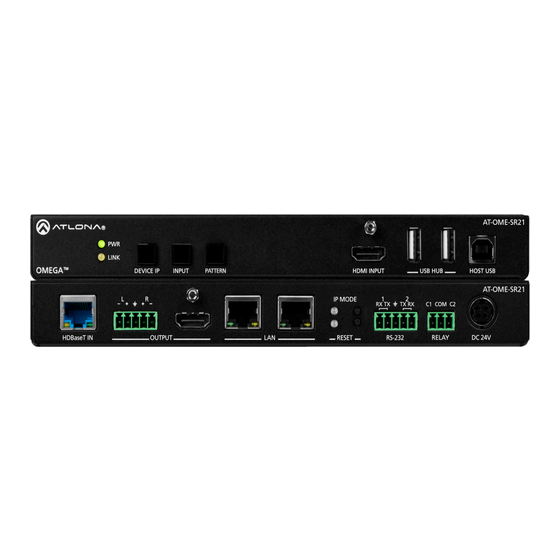
Page 7: Panel Description
Panel Description AT-OME-SR21 LINK OMEGA OMEGA DEVICE IP INPUT PATTERN HDMI IN USB HUB HOST USB AT-OME-SR21 IP MODE C1 COM C2 HDBaseT IN OUTPUT RESET RS-232 RELAY DC 24V PWR LED 10 HDBaseT IN Illuminates green when receiving power. Connect a compatible HDBaseT transmitter to this port. -
Page 8: Installation
Installation Captive Screw Connections RS-232 A 5-pin captive screw connector has been included for RS-232. NOTE: Port 1 will control the display and port 2 is for unit control. Pin out will be determined by the RS-232 cable and connect as RX (receive), TX (transmit) and (Ground). -
Page 9: Mounting Instructions
Installation Mounting Instructions The AT-OME-SR21 includes two mounting brackets and four mounting screws, which can be used to attach the units to any flat surface. 1. Remove the top 2 case screws on the side of the unit. 2. Align the mounting brackets to the side of the units. 3. -
Page 10: Cable Recommendation Guidelines
Installation Cable Recommendation Guidelines Refer to the tables below for recommended cabling when using Altona products with HDBaseT. The green bars indicate the signal quality when using each type of cable. Higher-quality signals are represented by more bars. CAT5e CAT6 CAT6a CAT7 Core... -
Page 11: Ip Modes
Installation IP Modes DHCP By default, the AT-OME-SR21 is set to DHCP mode. In this mode, when the AT-OME-SR21 is connected to the Local Area Network (LAN), it will automatically be assigned an IP address by the DHCP server (if available). Press the DEVICE IP button to show the IP address in the top left corner of the display. -
Page 12: Control
Control CEC is available for trigger through RS-232, TCP/IP, and WebGUI. The trigger commands for RS-232 and TCP/IP can be found within the API at https://atlona.com/pdf/AT-OME-SR21_API.pdf. RS-232 RS-232 control for connected devices and the unit are available through the RS-232 captive screw connection. The commands can be found within the API at https://atlona.com/pdf/AT-OME-SR21_API.pdf. -
Page 13: Webgui
WebGUI The AT-OME-SR21 includes a built-in webGUI, which allows easy remote management and control of all features. Follow the instructions below to access the webGUI. 1. Make sure that an Ethernet cable is connected between the LAN port on the AT-OME-SR21 and the network. 2. -
Page 14: Video Settings
webGUI Video Settings Select Video from the top navigation to adjust routing and video settings. HDCP Settings On - Sets the HDCP of the HDMI or HDBaseT ports to ON, allowing HDCP to switch between compliant and non-compliant according to the source and display HDCP handshake status. Off - Sets the HDBaseT or HDMI port to HDCP non-compliant. - Page 15 webGUI Output Input Selection - Use the drop down menu to switch between A/V Mute (no signal), HDMI, HDBaseT, internal pattern 1, internal pattern 2, and internal pattern 3 source signals. Scaler - When enabled, will display extra options. Output Resolution - Select the output resolution the source signal will be scaled to from the drop down menu. Scaling options: 1024x768, 1280x768, 1280x800, 1360x768, 1600x1200, 1920x1200, 2048x1080, 1280x720p50, 1280x720p60, 1920x1080p24, 1920x1080p25, 1920x1080p50, 1920x1080p60 (default), 3840x2160p24, 3840x2160p25, 3840x2160p30, 3840x2160p50,...
-
Page 16: Audio
webGUI Audio Select Audio from the top navigation to adjust volume, mute status, and EQ levels. Output Audio HDMI / L/R Enable - Unmutes the audio output signal, allowing audio to pass through the outputs. HDMI / L/R Disable - Mutes the audio output signal of the ports. No audio will pass when selected. NOTE: HDMI muting will mute the audio embedded on the HDMI output and L/R muting will mute the audio on the analog audio output. -
Page 17: Display
webGUI Display Select Display from the top navigation to adjust display control settings. Command: Power - Press to send the CEC power on or off command out through the HDMI port. Command: Volume - Press to send the CEC Volume up, down, or mute commands through the HDMI port. System Settings Display Auto Power - Enable to set the display to power off when the power settings are met. - Page 18 webGUI TCP/IP Settings of Controlled Device (only available when IP is selected) IP Mode - Toggle telnet login mode between Non-Login and Login. If set to Login, a username and password will be required to control the controlled device via TCP/IP. IP Address - Sets to the IP of the controlled device/display.
-
Page 19: Edid
webGUI RS-232 Select RS-232 from the top navigation to adjust the zone control parameters for the RS-232 port. RS-232 Parameter Setting RX RS232 1 - Select the baud rate, data bit, parity, and stop bit to match the SR21’s parameters. Defaults are 9600, 8, None, and 1. -
Page 20: Usb
webGUI Select USB from the top navigation for USB routing. USB Host Follow USB - Assigns the USB devices to follow the most recently connected Host (e.g. Computer). If a new USB device is connected, then it will auto switch to that Host. If the current host is disconnected, it will fall back to the previously connected active device. -
Page 21: Time
webGUI Time Select Time from the top navigation to select the time server for the unit to sync to. SNTP Configuration Server info - Select the time zone the unit will run in. If the unit has internet access, it can be set to sync to a server as well. -
Page 22: System
webGUI System Select System from the top navigation to adjust relay, network, or system options. Relay Control - Set the relay to either follow the display’s status (on: c1-close c2-open, off: c1-open c2-close) or be manually set using the selectors in the webGUI. Relay - When the relay is set to manual, select the sliders to open and close the com ports. - Page 23 webGUI Network MAC Address - Displays the MAC address of the unit. IP Mode - Switch between static and DHCP IP modes. IP, Netmask, Gateway - This will display the unit’s current DHCP IP settings. When set to static, fill in the IP address, netmask, and gateway.
- Page 24 webGUI System Front Panel Lock - Lock or unlock the front panel buttons. Reset to Default- Press the Factory Default button to set the unit back to all factory settings, including IP mode. Firmware update - Use the choose file button to search the local PC for the firmware file. Once selected, press the update button to start the firmware update.
-
Page 25: Hdbt
webGUI HDBT Select HDBT to open the HDBaseT cable test page. This page will check extender versions, cable status and length, and Video Quality. HDBT Test HDBaseT Zone - Use the drop down menu to select which HDBaseT input is being tested. Only active connections can be tested. -
Page 26: Appendix
Appendix Specifications Video HDMI HDCP UHD/HD/SD 4096x2160@60/50/30/25/24Hz 576p@50Hz 3840×2160@60/50/30/25/24Hz 576i@25Hz 1080p@60/59.9/50/30/29.97/25/24/23.98Hz 480p@60/59.96Hz 1080i@30/29.97/25Hz 480i@30Hz 720p@60/59.94/50Hz VESA 2560×1600 1280×800 2048×1536 1366×768 1920×1200 1360×768 1680×1050 1152×864 1600×1200 1024×768 1440×900 800×600 1400×1050 640×480 1280×1024 Scaler Up/Down 1024x768p@60 1920x1080p@24/25/50/60 1280x720p@50/60 1920x1200p@60 1280x768p@60 2048x1080p@60 1280x800p@60 3840x2160p@24/25/30/50/60 1360x768p@60 4096x2160p@24/25/30/50/60... - Page 27 Appendix Control RS-232 1-way connected display control 2-way device control and monitoring Supported baud rates: 2400, 4800, 9600, 19200, 38400, 57600, 115200 Full duplex 100Mbps CEC Support Relay Normally open (NO), adjustable Toggle and Pulse modes Electrical rating: 48V@1A Resolution / Distance 4K/UHD - Feet / Meters 1080p - Feet / Meters HDMI IN/OUT...
- Page 28 Appendix Weight Pounds Kilograms Device 1.96 0.89 Certification Device CE, FCC, UL Compliance NDAA-889 Warranty 3 years View the full warranty information here: https://atlona.com/warranty AT-OME-SR21...
- Page 29 International atlona.com 408.962.0515 41.43.508.4321 • • 35121-R6...
Need help?
Do you have a question about the ALTONA OMEGA AT-OME-SR21 and is the answer not in the manual?
Questions and answers