Panduit Atlona OmniStream AT-OMNI-512 Manual
R-type dual-channel networked av encoder
Hide thumbs
Also See for Atlona OmniStream AT-OMNI-512:
- Manual (97 pages) ,
- Installation manual (9 pages) ,
- Manual (68 pages)
Advertisement
Quick Links
Advertisement

Related Manuals for Panduit Atlona OmniStream AT-OMNI-512


Summary of Contents for Panduit Atlona OmniStream AT-OMNI-512
- Page 1 OmniStream R-Type ™ Dual-Channel Networked AV Encoder Atlona Manuals AT-OMNI-512 Networked AV...
- Page 2 Version Information Version Release Date Notes May 2023 Documentation typos corrected. AT-OMNI-512...
- Page 3 Sales, Marketing, and Customer Support Main Office International Headquarters Atlona Incorporated Atlona International AG 70 Daggett Drive Tödistrasse 18 San Jose, CA 95134 8002 Zürich United States Switzerland Office: +1.408.962.0515 Office: +41.43.508.4321 Sales and Customer Service Hours Monday - Friday: 6:00 a.m. - 4:30 p.m. (PST) Sales and Customer Service Hours Monday - Friday: 09:00 - 17:00 (UTC +1) https://atlona.com/...
- Page 4 Important Safety Information 9. Do not defeat the safety purpose of a polarized CAUTION or grounding-type plug. A polarized plug has two RISK OF ELECTRIC SHOCK blades with one wider than the other. A grounding DO NOT OPEN type plug has two blades and a third grounding CAUTION: TO REDUCT THE RISK OF prong.
- Page 5 Table of Contents Introduction Features Package Contents Introduction to OmniStream OmniStream 101 IP Address Assignment Network Bandwidth and OmniStream Compression Streams Sessions Subscribing to a Stream OmniStream Naming Schema Panel Description Installation RS-232 Connections IR Connections Connection Instructions Connection Diagram Getting Started Rebooting OmniStream ID Button...
- Page 6 Table of Contents Device Operation EDID Management Selecting an EDID Preset Adding a Custom EDID Device Control Downstream Control using RS-232 Control using TCP Proxy Downstream Control using Triggering Upstream Control using RS-232 Upstream Control using IR AES67 Audio Scrambling Slate / Logo Insertion Adding Slates / Logos Deleting Slates...
- Page 7 Introduction The Atlona AT-OMNI-512 is a networked AV encoder with two independent channels of encoding for two HDMI sources up to 4K/60 4:4:4 and HDR (High Dynamic Range), plus embedded audio and RS-232 or IR control pass- through. OmniStream is designed for high performance, flexible distribution of AV over standard, off-the-shelf Gigabit Ethernet switches in commercial audiovisual applications.
- Page 8 Introduction to OmniStream OmniStream 101 OmniStream products are similar in principle to matrix switch endpoints: A/V signals are sent from one point (transmitter) to another point (receiver) over category cable. However, OmniStream stands apart from matrix switchers, in that it is an IP-based solution, allowing this data to be sent over a standard IP network. In addition, these endpoints are referred to as encoders and decoders.
- Page 9 Introduction to OmniStream Network Bandwidth and OmniStream Compression When sending video and audio over a network, the available bandwidth needs to be managed. Gigabit Ethernet switches are very common and can take advantage of installed Category 5e cable. 10-Gigabit Ethernet switches are available, but are more expensive per port and require Category 6A cable or better.
- Page 10 Introduction to OmniStream Subscribing to a Stream To receive information from an encoder, the decoder must subscribe to the multicast IP address and UDP port of the stream(s). Note that the decoder does not subscribe to the session, but to the stream(s) within the session. The process of subscribing is similar to changing the channel on a Set-Top Box.
- Page 11 Introduction to OmniStream DEFINITIONS Stream – Describes the video, audio, or any data that is transmitted from an encoder over the network. Multicast IP Address – A class-D IP address assigned to a stream. UDP Port – User Datagram Protocol (UDP) port. Part of the network addressing scheme to send and receive data to the proper destination on a network.
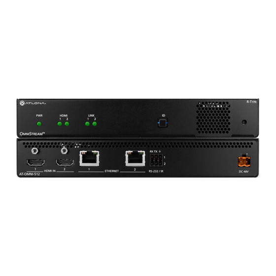
- Page 12 Panel Description HDMI LINK HDMI LINK TREAM Front TREAM RX TX RX TX RS-232 / IR HDMI IN ETHERNET DC 48V AT-OMNI-512 HDMI IN ETHERNET RS-232 / IR DC 48V AT-OMNI-512 Rear Reboot button This LED indicator is green when the unit is powered Press this button, using a small, pointed object to and booted.
- Page 13 Installation RS-232 Connections The AT-OMNI-512 provides RS-232 over IP which allows communication between an automation system and an RS- 232 device. This step is optional. Either the top three or bottom three set of terminals can be used for RS-232. 1.
- Page 14 Installation IR Connections The same port that provides RS-232 connections also supports bidirectional IR pass-through, allowing a device to be controlled from either the headend or the decoder endpoint. This step is optional. Either the top three or bottom three set of terminals can be used for IR. Only the RS-232 2 port (bottom set of connectors) supports both RS-232 and IR.
- Page 15 Installation Connection Instructions 1. Connect an Ethernet cable from the ETHERNET 1 and ETHERNET 2 ports on the encoder to a PoE-capable switch on the Local Area Network (LAN). Note that if a PoE-capable switch is not available, the 48V DC power supply (sold separately) must be connected to the encoder.
- Page 16 Installation Connection Diagram Source M NI AT-OMNI-512 Display PoE Network Switch M NI AT-OMNI-121 AT-OMNI-512...
- Page 17 Getting Started Rebooting OmniStream To reboot the OmniStream encoder, press and release the recessed button, on the far-right side of the unit, using a small, pointed object. Rebooting the encoder does not reset the encoder to factory-default settings. HDMI LINK TREAM RX TX ID Button...
- Page 18 Getting Started Resetting to Factory-Defaults WARNING: Performing a factory-default reset will erase all user-programmed settings from the encoder. IP settings are not preserved. Using the ID button 1. Press and hold the ID button for approximately 30 seconds. 2. The LED indicators on the front panel will flash, then turn “off.” 3.
- Page 19 Getting Started LED Indicators The following table provides a listing of front-panel LED indicators and their status: Description • If using a PoE switch, make sure that the port on the switch that is connected to the encoder, has PoE enabled. When the encoder is powered using PoE, the PWR indicator will be green.
- Page 20 Getting Started Accessing the Web Server In order to access the web server of the desired encoder/decoder, the IP address of the encoder must be known. This can be accomplished by using any of the following methods: 1) Running IP scanner software or 2) accessing the encoder using the domain name.
- Page 21 Basic Configuration Tutorial This section provides a tutorial on configuring two AT-OMNI-512 dual-channel encoders and one AT-OMNI-121 single-channel decoder. Make sure the encoder is connected to a source device and that the decoder is connected to a display. Both the encoder and decoder should be connected to the same local network. Refer to Connection Instructions (page 15) for more information.
- Page 22 Basic Configuration Tutorial Setting the System Mode The AT-OMNI-512 offers two system modes. These modes will optimize the video, based on the type of information that is being displayed and/or the desired features. 1. Login to each encoder and click System Information in the menu bar. 2.
- Page 23 Basic Configuration Tutorial Configuring Inputs The Input page is used to verify that the encoder recognizes the source device. This page is also used to set the EDID, HDCP version, and provides detailed information about the source signal. The following procedure should be performed on both AT-OMNI-512 encoders.
- Page 24 Basic Configuration Tutorial 6. The Video section provides information about the input signal: color depth, subsampling, color space, resolution, frame rate, and HDR (High Dynamic Range). If the HDR indicator is green, this will indicate that HDR content is being transmitted from the source device.
- Page 25 Basic Configuration Tutorial Encoder Settings The Encoding page is used to assign an input to an encoder. In addition, this page allows video settings, such as the maximum bit rate, bit depth, and chroma subsampling to be set. Video thumbnails of the source device can also be displayed on this page.
- Page 26 Basic Configuration Tutorial Creating a Session Before the video and audio (if any) can be sent out over the network, a session must be created on the encoder. The session assigns each stream to a unique multicast IP address and UDP port assignment. Sessions are always created on encoders.
- Page 27 Basic Configuration Tutorial Table 2.1 - Recommended multicast IP address for video, audio, and data streams. Stream Video Audio Data (Control) 226.0.0.1 226.0.10.1 226.0.20.1 First source 226.0.0.2 226.0.10.2 226.0.20.2 Second source 226.0.0.n 226.0.10.n 226.0.20.n nth source Table 2.2 - Recommended UDP ports for video, audio, and data streams. Stream Video Audio...
- Page 28 Basic Configuration Tutorial Subscribing to an Encoder The next step is to configure the decoder so that it is able to receive video, audio, and/or data (control) streams from the encoder. This process is referred to as “subscribing to the encoder”. Video Configuration 1.
- Page 29 Basic Configuration Tutorial Audio Configuration 1. Locate the Input 3 window group and verify that the Enable toggle switch is enabled. When enabled, the toggle switch will be orange. Perform the same procedure for the Input 4 window group. 2. Under the Input 3 window group, enter 226.0.10.1 in the Multicast address field. Under the Input 4 window group, enter 226.0.10.2 in this field.
- Page 30 Basic Configuration Tutorial Configuring the HDMI Output Stream 1. Click HDMI Output in the menu bar. 2. The Descrambling > Enable toggle switch is enabled by default. When enabled, this toggle will be orange. For this example, leave the setting enabled. 3.
- Page 31 Basic Configuration Tutorial 6. Scroll down to the Audio > Input field and select the desired audio stream. Referring to Table 2.3 (shown below), the audio stream that is associated with encoder 1 is Input 3. Therefore, ip_input3 (226.0.10.1:1100) is selected.
- Page 32 Basic Configuration Tutorial Figure 3.1 - Basic OmniStream setup with Decoder #1 subscribed to Encoder Encoder #2 Session 1 Destination IP Address (Video): 226.0.0.2 G am UDP Port (Video): 1000 Destination IP Address (Audio): 226.0.10.2 Gaming Console UDP Port (Audio): 1100 LI NK M NI...
- Page 33 Basic Configuration Tutorial Troubleshooting If no video and/or audio is present on the display, check the following for both Encoder #1 Encoder unless otherwise noted. Encoder Checklist • Verfiy that all encoders and decoders are set to the same system mode. In this tutorial, both encoders and the decoder should be set to VCx.
- Page 34 Basic Configuration Tutorial Decoder Checklist • Verfiy that all encoders and decoders are set to the same system mode. In this tutorial, both encoders and the decoder should be set to VCx. Refer to Setting the System Mode (page 22). •...
- Page 35 Device Operation EDID Management OmniStream encoders provide EDID management for each input. The encoder can be assigned one of several included EDID presets or can be assigned a custom EDID. Raw EDID data can be copied from displays or other sink devices, that are connected to OmniStream decoders.
- Page 36 Device Operation Adding a Custom EDID Encoders can be loaded with a custom EDID. The raw EDID data must be in hexadecimal format. Commas or spaces are not permitted. 1. Login to the encoder and click the EDID menu. 2. Click the icon in the lower-right corner of the screen.
- Page 37 Device Operation Device Control Downstream Control using RS-232 Control using RS-232 is converted and transmitted over IP by the encoder. Destination devices can either be the IP address of a display or a decoder. 1. Login to the encoder and click the Serial menu. 2.
- Page 38 Device Operation 6. Click the Session menu. 7. Under the desired Session, locate the AUX section and click the Source drop-down list to select the desired serial port. 8. Click the Enable toggle switch to display the additional fields. 9. Enter the destination IP address and UDP port in the Destination IP address and Destination UDP port fields, respectively.
- Page 39 Device Operation 11. Login to the decoder and click the IP Input menu. 12. Locate an Input that does not contain a defined Multicast address field. In this example, Input 5 will be used. Note that if a multicast address was used in Step 9, then that multicast address must be entered in the Multicast address field under Input 5.
- Page 40 Device Operation 18. Under the Serial configuration window group, click the Port drop-down list and select the desired port. 19. Click the Mode drop-down list and select output. 20. Click SAVE. Control using TCP Proxy TCP/IP traffic received by an encoder or decoder, on the defined IP:Port socket, are translated to RS-232, allowing both control of source or display.
- Page 41 Device Operation 4. Under the Serial Configuration window group, click the Port drop-down list and select the desired serial port. 5. Click the Mode drop-down list and select tcpproxy. 6. Click the TCPProxy > Interface drop-down list and select the desired Ethernet interface. 7.
- Page 42 Device Operation Downstream Control using Triggering TCP/IP traffic received by an encoder or decoder, on the defined IP:Port socket, are translated to RS-232, allowing both control of source or display. Control is achieved using a control system, where all control commands are stored. Option 1: Defining Commands on the Decoder 1.
- Page 43 Device Operation 8. For each of the available commands, click the Mode drop-down list and select raw. The available commands are: Display On, Display Off, Volume Up, and Volume Down. 9. Enter the command data in either ASCII or hexadecimal format using the ASCII or HEX fields. 10.
- Page 44 Device Operation Option 2: Defining Commands on the Encoder 1. Login to the encoder and click the Serial menu. 2. For each of the available commands, click the Interpret on drop-down list and select decoder. The available commands are: Display On, Display Off, Volume Up, and Volume Down. NOTE: Setting the Interpret on drop-down list to encoder implies that commands are defined/ stored on the encoder.
- Page 45 Device Operation 5. Click the Session menu. 6. Under the desired Session, locate the AUX section, click the Source drop-down list, and select Commands. 7. Click the Enable toggle switch to display the additional fields. 8. Enter the destination IP address and UDP port, of the decoder, in the Destination IP address and Destination UDP port fields, respectively.
- Page 46 Device Operation 14. Click the Serial menu. 15. Under Serial port configuration, set the Mode drop-down list to serial. 16. Click the SAVE button. 17. Under Serial configuration, select the desired port. 18. Click the Mode drop-down list and select output. 19.
- Page 47 Device Operation Upstream Control using RS-232 The serial interface provides RS-232 control of both downstream and upstream devices. Source control is provided by enabling bidirectional communication. 1. Login to the decoder and click the Serial menu. 2. Under the Serial Port Configuration window group, click the Mode drop-down list and select Serial. 3.
- Page 48 Device Operation 8. Enter the destination IP address (the IP address of the encoder) and UDP port in the Bidirectional > Destination IP address and Bidirectional > Destination UDP port field, respectively. 9. Click the Bidirectional > Enabled toggle switch to the enabled position.
- Page 49 Device Operation 20. Click the AUX > Bidirectional toggle switch to enable it. When enabled, the toggle switch will be orange. 21. Click the SAVE button. Upstream Control using IR To control of headend source from downstream, refer to the Upstream Control using RS-232 (page 47) instructions.
- Page 50 Device Operation AES67 Audio AES67 audio is a standard for high-performance audio streaming over IP, providing several features such as synchronization, media clock identification, and connection management. AES67 does not support bitstream/ compressed audio formats, such as Dolby® Digital, and others. Source audio must be transmitted as LPCM up to eight channels at 192 kHz / 24-bit.
- Page 51 Device Operation 5. Go to the decoder and click the SAP Listener menu. 6. Click the Enable toggle switch to enable the SAP listener. When enabled, the toggle switch will be orange. 7. Click the SAVE button. 8. Click the IP Input menu. 9.
- Page 52 Device Operation 12. Click the HDMI Output menu. 13. Locate the Audio section, click the Audio > Input drop-down list, and select the input that was configured in Steps 10 and 11. 14. Click the Enable AES67 toggle switch to enable it. When enabled, the toggle switch will be orange. 15.
- Page 53 Device Operation Scrambling OmniStream supports 128-bit Advanced Encryption Standard (AES) scrambling and is required for HDCP-encrypted streams. Scrambling can be enabled or disabled through the web server, and can be applied to individual sessions. In order for scrambling to function properly, it must be enabled on both the encoder session and all decoders subscribed to a stream that is a part of a scrambled session.
- Page 54 Device Operation Slate / Logo Insertion The difference between a “slate” and “logo” is in the size of the image and how it is used: Logos are classified as smaller, low-resolution images that can be positioned at specified locations on the screen. Slates occupy the entire screen.
- Page 55 Device Operation 14. Click Encoding in the menu bar. 15. Click the Slate mode drop-down list, and select Off, Manual, or Auto. Slate mode Description Disables the image from being displayed. Manual The image will always be displayed, superimposed on the source signal, and will remain even if the source signal is lost.
- Page 56 Device Operation Text Insertion Text can be inserted and scrolled across the screen, making it useful for messages and notifications. Several options are available when using text: Scroll speed adjustment (forward, reverse, or static), number of iterations, text color, vertical / horizontal position, as well as transparency. 1.
- Page 57 Device Operation Configuring a Static IP Address There will be situations where it is desirable for the encoder to be assigned a static IP address. Some IT environments prefer this method, as opposed to having a DHCP server dynamically assign IP addresses. If the encoder is unable to detect a DHCP server within 15 seconds, then Automatic Private IP Addressing (APIPA) will be used to assign the encoder an address within the IPv4 address block 169.254.xxx.xxx/16.
- Page 58 Configuration and Management Interfaces Web Server NOTE: This section assumes that the System mode is set to VCx. If VC-2 Video or VC-2 PC Application is used, some features on these pages will not be available. System information page Firmware version The version of firmware that the encoder is running.
- Page 59 Configuration and Management Interfaces Description Provides the option of assigning descriptive name to the unit. Location Provides the option of assigning a description of where the unit is located. Timezone Displays the time zone format. Click the SET TIMEZONE button, to assign the time zone. Date/Time Displays the current date and time.
- Page 60 Configuration and Management Interfaces FACTORY RESET Click this button to reset the encoder to factory-default settings. When performing a factory reset, the following options can be selected, by clicking the check box. If no options are selected, then the encoder is reset with no factory-default settings.
- Page 61 Configuration and Management Interfaces SAP Listener page Enable Click this toggle to enable or disable SAP. This feature is enabled when the toggle switch is orange. This is the default setting. If an SAP announcement is picked up, it will be displayed below the SAP window group (as shown here).
- Page 62 Configuration and Management Interfaces Input page Input window groups The following fields apply to both the Input 1 and Input 2 window groups. Name The name of the input. This field cannot be changed. Cable present This indicator will be red if the encoder is unable to detect the source signal.
- Page 63 Configuration and Management Interfaces EDID Description ATL 1280x800 RGB DVI PCWXGADVI 1280x800 formatted as DVI ATL 1280x800 RGB PCWXGA2CH 1280x800p60 PC format with two-channel PCM audio ATL 1280x800 RGB TVWXGA2CH 1280x800p60 TV format with two-channel PCM audio ATL 2160P 2CH 3840x2160p30 with two-channel PCM audio ATL 2160P MCH 3840x2160p30 with multichannel PCM audio...
- Page 64 Configuration and Management Interfaces SAVE Click this button to save all changes under the Input window group. Video generator window groups The following fields apply to both the Video generator 1 and Video generator 2 window groups. This signal can be used to test the video capability of the network.
- Page 65 Configuration and Management Interfaces EDID page This page is used to show details about each EDID that is loaded on the unit. Product Displays the SKU of the OmniStream encoder or the Product and Vendor for any EDID captured using a decoder.
- Page 66 Configuration and Management Interfaces Encoding page Encoder window groups The following fields apply to both the Encoder 1 and Encoder 2 window groups. Name The name of the encoder. This field cannot be changed. Input Click this drop-down list to select the input. Available options are: not used, hdmi_input1, and video_ generator1.
- Page 67 Configuration and Management Interfaces Slate mode Click this drop-down list to enable or disable slate mode. Available values are: off, manual, and auto. Slate mode Description Disables the image from being displayed. Manual The image will always be displayed, superimposed on the source signal, and will remain even if the source signal is lost.
- Page 68 Configuration and Management Interfaces Serial page Serial port configuration window groups The following fields apply to both Serial port configuration window groups. Name The name of the serial port. This field cannot be changed. Supported Modes Displays the supported protocols for the serial port. This field cannot be changed.
- Page 69 Configuration and Management Interfaces Flow Control Click this drop-down list to select the type of flow control: none, xonxoff, or hw. SAVE Click this button to commit all changes within the Serial port configuration window group. Serial configuration window groups The following fields apply to both Serial configuration window groups.
- Page 70 Configuration and Management Interfaces Session page Session window groups The following fields apply to all Session window groups. The AT-OMNI-512 supports up to four sessions. Name The name of the session. This field cannot be changed. Interface The name of the interface being used. This field cannot be changed. AT-OMNI-512...
- Page 71 Configuration and Management Interfaces Enable Click this switch to enable or disable the Session Announcement Protocol (SAP) announcements. When enabled, the toggle switch will be orange. Interval Sets the announcement interval. Name The name of the SAP session. By default, this is the same as the session name.
- Page 72 Configuration and Management Interfaces Audio Source Click this drop-down list to select the desired input. Available values are: Not used, audio_generator1, and hdmi_input1. Enable AES67 If AES67 audio is used, this indicator will be green. Enable Click this toggle switch to enable or disable the audio signal.
- Page 73 Configuration and Management Interfaces Listen port Enter the listening port in this field. SAVE Click this button to commit all changes within the Session window group. AT-OMNI-512...
- Page 74 Configuration and Management Interfaces Logo page New logo window group Name Enter a name for the logo in this field. Choose File Click this button to select the logo file to be uploaded. Files must be in .png or .svg format and must not exceed 5 MB (5120000 bytes) in size.
- Page 75 Configuration and Management Interfaces Aspect Ratio Click this drop-down list to select the type of aspect ratio to be applied to the logo. Horizontal (%) Enter the horizontal position of the logo based on the resolution of the video stream. Vertical (%) Enter the vertical position of the logo based on the resolution of the video stream.
- Page 76 Configuration and Management Interfaces Text page Text insertion window groups The following fields apply to both Text insertion window groups. Enabled Click this toggle switch to enable or disable the text. When the toggle switch is orange, the text will be enabled. Text Enter the desired text in this field.
- Page 77 Configuration and Management Interfaces Horizontal Enter the horizontal position of the text, based on the resolution of the video stream. Vertical Enter the vertical position of the text, based on the resolution of the video stream. Width Enter the width of the text. This value is based on the horizontal resolution of the video stream.
- Page 78 Configuration and Management Interfaces Network page Network window groups The following fields apply to both Network window groups. Name Displays the name of the Ethernet interface. This field cannot be changed. Enabled This indicator displays the state of the Network Interface Card (NIC). If the indicator is green, then the NIC is in the up/up state.
- Page 79 Configuration and Management Interfaces Link speed Displays the Ethernet interface link speed in Mbps. This field cannot be modified. MAC address Displays the MAC address of the Ethernet interface. Enable Click this toggle switch to enable or disable Telnet. If disabled, then Telnet sessions to the encoder cannot be established.
- Page 80 Configuration and Management Interfaces PTP page The PTP page provides options for adjust Precision Time Protocol (PTP) for AES67 audio streams. PTP is used by AES67 to keep all audio streams synchronized. For a system utilizing PTP, all devices undergo an automatic self-election process to choose the device to be used as the PTP grandmaster (GM) clock, based on the accuracy of the device’s clock and the device’s configured priority.
- Page 81 Configuration and Management Interfaces Displays the TTL value. The default IPV4 TTL value used for PTP is 8. Is GM If the indicator is green, then this interface is the PTP GM. GM Identity The grandmaster clock identity. Master Offset Displays the grandmaster clock offset.
- Page 82 Configuration and Management Interfaces LLDP page The Link Layer Discovery Protocol (LLDP) page returns information about the switch that the encoder is connected to. If both interfaces are connected to the switch, then two eth window groups will be displayed. NOTE: LLDP must be enabled on the switch that the encoders are connected to, in order for the switch information to be displayed.
- Page 83 Configuration and Management Interfaces Configuration page Import configuration Choose File Click this button to select the desired configuration file to be uploaded. IMPORT Click this button to upload the selected configuration file to the encoder. The hostname, specific to the configuration filename, will be ignored.
- Page 84 Configuration and Management Interfaces Users page User window groups The following fields apply to all User window groups. Encoders have two usernames, by default: admin and operator. Username Enter the desired username in this field. Role Click this drop-down list to select the desired role of the user. New password Enter the desired password for the username in this field.
- Page 85 Configuration and Management Interfaces License page This page displays all installed licenses and allows additional licenses to be installed. License Key Enter the license key in this field. INSTALL LICENSE Click this button to validate and install the license. AT-OMNI-512...
- Page 86 Configuration and Management Interfaces Upgrade page This page is used to update the firmware on the encoder. Choose File Click this button to select the firmware file to be uploaded. UPLOAD Click this button to upload the selected firmware file. AT-OMNI-512...
- Page 87 Appendix Updating the Firmware Follow the procedure below to update OmniStream units using the built-in web server. 1. Launch the desired web browser and enter the IP address of the encoder/decoder in the address bar. 2. Enter the username and password. Note that the password field will always be masked. The default credentials are: admin Username:...
- Page 88 Appendix Performing a Link Test Follow the procedure below to perform a link integrity test between an encoder and decoder(s). 1. Launch a web browser and enter the IP address of the encoder in the address bar. 2. Open another tab in the browser and enter the IP address of the subscribing decoder in the address bar. 3.
- Page 89 Appendix 6. An orange screen with a progress bar will be displayed during the testing procedure. 7. After the test, the encoder web page will automatically redirect to the Notifications tab where the user can see the results. If the test passed, information similar to the following will be displayed. Note the information in the Description field: “100% of packets received by ...”...
- Page 90 Appendix If the test fails, it could be that less than 100% of packets are received, indicating connectivity, but with some amount of packet loss. If it shows “No one replied!” or if the target decoder is not shown in results, it could indicate that there is a connectivity issue or that the decoder is not subscribed to the correct video multicast address.
- Page 91 Appendix Mounting Instructions The AT-OMNI-512 encoder includes two mounting 6. Mount the unit using the oval-shaped holes, on each brackets and four mounting screws, which can be used rack ear. If using a drywall surface, a #6 drywall to attach the unit to any flat surface. screw is recommended.
- Page 92 Appendix Rack Tray for OmniStream OmniStream encoders can also be mounted in the OmniStream rack tray (AT-OMNI-1XX-RACK-1RU). The rack tray is sold separately and provides easy mounting and organization of up to two OmniStream encoders/decoders in a convenient 1U rack tray. The OmniStream rack tray can be purchased directly from Atlona. 1.
- Page 93 Appendix Specifications Video Signal HDMI Copy Protection HDCP 2.2 UHD/HD/SD 4096×2160 (DCI) @ 30/24 Hz 1920x1080i @ 25/29.97/30 Hz 3840×2160 (UHD) @ 60/50/24/25/30 Hz 1280x720p @ 30/50/59.94/60 Hz 1920x1080p @ 23.98/24/25/29.97/30/50 /59.94/60 Hz VESA 2560x1600 1366x768 1920x1200 1360x768 1680x1050 1280x1024 1600x1200 1280x800 1600x900...
- Page 94 Appendix Protocols Video Streaming Audio Streaming RTP, up to 7.1 channels AES67, up to LPCM 7.1 channels Addressing DHCP, static Encryption AES-128 QoS Tagging RFC 2475 Discovery Multicast DNS, LLDP, SAP Management HTTPS, SSH, Telnet, and WebSockets with TLS IP Multicast IGMPv2 and IGMPv3 support Graphics Features Text Insertion...
- Page 95 Appendix Environmental Fahrenheit Celsius Operating Temperature +14 to +122 -10 to +50 Storage Temperature -14 to +140 °F -10 to +60 °C Operating Humidity (RH) 20% to 95%, non-condensing Maximum Operating Altitude 2000 meters Cooling System Front-to-rear airflow, temperature-controlled fans Chassis Dimensions (H x W x D) 1.34 in x 8.19 in x 4.41 in...
- Page 96 International atlona.com 408.962.0515 41.43.508.4321 • • 35207-R10...
Need help?
Do you have a question about the Atlona OmniStream AT-OMNI-512 and is the answer not in the manual?
Questions and answers