
Related Manuals for Panduit ATLONA OmniStream 101


Summary of Contents for Panduit ATLONA OmniStream 101
- Page 1 OmniStream ™ Using with Velocity Device Manager ™ Atlona Manuals Velocity ™ Control Systems...
- Page 2 Version Information Version Release Date Notes May 2023 Initial release Using OmniStream with Velocity Device Manager ™ ™...
- Page 3 Sales, Marketing, and Customer Support Main Office International Headquarters Atlona Incorporated Atlona International AG 70 Daggett Drive Tödistrasse 18 San Jose, CA 95134 8002 Zürich United States Switzerland Office: +1.408.962.0515 Office: +41.43.508.4321 Sales and Customer Service Hours Monday - Friday: 6:00 a.m. - 4:30 p.m. (PST) Sales and Customer Service Hours Monday - Friday: 09:00 - 17:00 (UTC +1) https://atlona.com/...
- Page 4 Safety and Certification 9. Do not defeat the safety purpose of a polarized CAUTION or grounding-type plug. A polarized plug has two RISK OF ELECTRIC SHOCK blades with one wider than the other. A grounding DO NOT OPEN type plug has two blades and a third grounding CAUTION: TO REDUCT THE RISK OF prong.
-
Page 5: Table Of Contents
Table of Contents Introduction to OmniStream OmniStream 101 IP Address Assignment Network Bandwidth and OmniStream Compression Streams Sessions Subscribing to a Stream OmniStream Naming Schema Getting Started Accessing OmniStream Devices LED Indicators Basic Configuration Tutorial Physical Connections Setting the System Mode Configuring Inputs Encoder Settings Creating a Session... - Page 6 Table of Contents Creating Video Walls Creating Presets Creating and Using Drop Zones Custom Drop Zones Configuring Redundant Streams Redundancy Grace Period AES67 Audio Encoder Grouping Daisy-Chaining Encoders Scrambling Descrambling Fast Switching Fast Switching FAQs Slate / Logo Insertion Adding Slates / Logos Deleting Slates Deleting Logos Text Insertion...
-
Page 7: Introduction To Omnistream
Introduction to OmniStream OmniStream 101 OmniStream products are similar in principle to matrix switch endpoints: A/V signals are sent from one point (transmitter) to another point (receiver) over category cable. However, OmniStream stands apart from matrix switchers, in that it is an IP-based solution, allowing this data to be sent over a standard IP network. In addition, these endpoints are referred to as encoders and decoders. -
Page 8: Network Bandwidth And Omnistream Compression
Introduction to OmniStream Network Bandwidth and OmniStream Compression When sending video and audio over a network, the available bandwidth needs to be managed. Gigabit Ethernet switches are very common and can take advantage of installed Category 5e cable. 10-Gigabit Ethernet switches are available, but are more expensive per port and require Category 6A cable or better. -
Page 9: Subscribing To A Stream
Introduction to OmniStream Subscribing to a Stream To receive information from an encoder, the decoder must subscribe to the multicast IP address and UDP port of the stream(s). Note that the decoder does not subscribe to the session, but to the stream(s) within the session. The process of subscribing is similar to changing the channel on a Set-Top Box. -
Page 10: Omnistream Naming Schema
Introduction to OmniStream DEFINITIONS Stream – Describes the video, audio, or any data that is transmitted from an encoder over the network. Multicast IP Address – A class-D IP address assigned to a stream. UDP Port – User Datagram Protocol (UDP) port. Part of the network addressing scheme to send and receive data to the proper destination on a network. -
Page 11: Getting Started
Getting Started Accessing OmniStream Devices The Velocity Device Manager uses multicast Domain Name Server (mDNS) to automatically discover each encoder on the network. By default, the OmniStream devices are set to DHCP mode, allowing a DHCP server (if present) to assign the encoder an IP address. - Page 12 Getting Started 4. The Velocity home screen will be displayed. 5. Click the icon in the upper-left corner of the screen and select Management > Device Manager. 6. All available encoders will be displayed under the Unassigned category. When an encoder is unassigned, it means that it has not been assigned to a site, building, and/or room.
- Page 13 Getting Started If a DHCP server is not found within 60 seconds, the encoder will be placed in Auto IP (APIPA) mode and assigned an IP address within the range of 169.254.xxx.xxx/16. If this occurs, configure the network interface of the computer that is running Velocity, located on the same subnet (169.254.xxx.xxx, subnet mask 255.255.0.0).
-
Page 14: Led Indicators
Getting Started LED Indicators The following table provides a general overview of the front-panel LED indicators and their status. Depending upon the device (encoder or decoder), some LED indicators may not be present. Description • If using a PoE switch, make sure that the port on the switch that is connected to the encoder, has PoE enabled. -
Page 15: Basic Configuration Tutorial
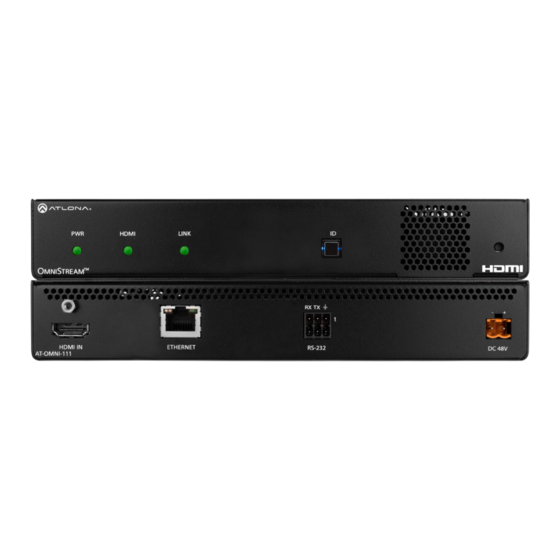
Basic Configuration Tutorial This section provides a tutorial on configuring two AT-OMNI-111 single-channel encoders and one AT-OMNI-121 single-channel decoder. Make sure the encoder is connected to a source device and that the decoder is connected to a display. Both the encoder and decoder should be connected to the same local network. Physical Connections G am Encoder #2... -
Page 16: Setting The System Mode
Basic Configuration Tutorial Setting the System Mode OmniStream offers three system modes. These modes will optimize the video, based on the type of information that is being displayed and/or the desired features. 1. Under DEVICE LIST, select the encoder. 2. Click the System Mode drop-down list and select VCx. This mode will provide access to all of OmniStream 2.0 features. -
Page 17: Configuring Inputs
Basic Configuration Tutorial Configuring Inputs The INPUT page is used to verify that the encoder recognizes the source device. This page is also used to set the EDID, HDCP version, and provides detailed information about the source signal. The following procedure should be performed on both AT-OMNI-111 encoders. - Page 18 Basic Configuration Tutorial 4. Click the HDCP > Version drop-down list to restrict HDCP to a particular version. By default, this is set to 2.2 and this setting should be used for most applications. 5. The Video section provides information about the input signal: color depth, subsampling, color space, resolution, frame rate, and HDR (High Dynamic Range).
-
Page 19: Encoder Settings
Basic Configuration Tutorial Encoder Settings The INPUT page is also used to assign an input to an encoder. The Encoder window groups allow video settings, such as the maximum bit rate, bit depth, and chroma subsampling to be set. Video thumbnails of the source device can also be displayed on this page. -
Page 20: Creating A Session
Basic Configuration Tutorial Creating a Session Before the video and audio (if any) can be sent out over the network, a session must be created on the encoder. The session assigns each stream to a unique multicast IP address and UDP port assignment. Sessions are always created on encoders. - Page 21 Basic Configuration Tutorial Table 2.1 - Recommended multicast IP address for video, audio, and data streams. Stream Video Audio Data (Control) 226.0.0.1 226.0.10.1 226.0.20.1 First source 226.0.0.2 226.0.10.2 226.0.20.2 Second source 226.0.0.n 226.0.10.n 226.0.20.n nth source Table 2.2 - Recommended UDP ports for video, audio, and data streams. Stream Video Audio...
-
Page 22: Subscribing To An Encoder
Basic Configuration Tutorial Subscribing to an Encoder The next step is to configure the decoder so that it is able to receive video, audio, and/or data (control) streams from the encoder. This process is referred to as “subscribing to the encoder”. Video Configuration 1. -
Page 23: Audio Configuration
Basic Configuration Tutorial Audio Configuration 1. Locate the IP Input 3 window group and verify that the Enable toggle switch is enabled. When enabled, the toggle switch will be green. Perform the same procedure for the IP Input 4 window group. 2. -
Page 24: Configuring The Hdmi Output Stream
Basic Configuration Tutorial Configuring the HDMI Output Stream 1. Click HDMI OUTPUT in the menu bar, locate the HDMI Output 1 window group, and verify that the Descrambling > Enabled toggle switch is enabled. When enabled, this toggle will be green. 2. - Page 25 Basic Configuration Tutorial 5. Scroll down to the Audio > Input field and select the desired audio stream. Referring to Table 1.3 (shown below), the audio stream that is associated with encoder 1 is Input 3. Therefore, IP Input 3 - 226.0.10.1:1000 | 10.1.0.111 is selected.
- Page 26 Basic Configuration Tutorial The decoder should now display the content of the source device connected to HDMI IN on the encoder. Figure 3.1 shows the completed configuration. To switch between video sources, click the Video > Input drop-down list and select the desired stream. To switch between audio streams, click the Audio >...
-
Page 27: Troubleshooting
Basic Configuration Tutorial Troubleshooting If no video and/or audio is present on the display, check the following: Encoder Checklist • Verify that all encoders and decoders are set to the same system mode. In this tutorial, both encoders and the decoder should be set to VCx. -
Page 28: Decoder Checklist
Basic Configuration Tutorial Decoder Checklist • Verify that all encoders and decoders are set to the same system mode. In this tutorial, both encoders and the decoder should be set to VCx. Refer to Setting the System Mode (page 16). •... -
Page 29: Device Operation
Device Operation EDID Management OmniStream encoders provide EDID management for each input. The encoder can be assigned one of several included EDID presets or can be assigned a custom EDID. Raw EDID data can be copied from displays or other sink devices, that are connected to OmniStream decoders. -
Page 30: Adding A Custom Edid
Device Operation Adding a Custom EDID Encoders can be loaded with a custom EDID. The raw EDID data must be in hexadecimal format. Commas or spaces are not permitted. 1. Click the INPUT menu. Click the EDID drop-down list, within the desired Input window group, and select the Add Custom EDID. -
Page 31: Deleting A Custom Edid
Device Operation Deleting a Custom EDID 1. Click INPUT in the menu bar and click the EDID drop-down list, within the desired Input window group, and select the EDID to be deleted. NOTE: Only custom EDID data can be added or deleted. EDID presets cannot be modified. 2. -
Page 32: Device Control
Device Operation Device Control Downstream Control using RS-232 Control using RS-232 is converted and transmitted over IP by the encoder. Destination devices can either be the IP address of a display or a decoder. 1. Login to the encoder and click the SERIAL menu. Under the Serial Port 1 window group, click the Mode drop- down list and select Serial. - Page 33 Device Operation 5. Click the SESSION menu. Under the desired stream, locate the Control/Serial section and click the Source drop-down list to select the desired serial port. 6. Click the Enable Aux toggle switch to display the additional fields. 7. Enter the destination IP address and UDP port in the Destination Multicast/Unicast Address and Destination UDP Port fields, respectively.
- Page 34 Device Operation 9. Login to the decoder and click the IP INPUT menu. Locate an Input that does not contain a defined Multicast Address field. In this example, Input 5 will be used. Note that if a multicast address was used in Step 7, then that multicast address must be entered in the Multicast Address field under Input 5.
- Page 35 Device Operation 15. Under the Serial Configuration 1 window group, click the Port drop-down list and select the desired port. 16. Click the Mode drop-down list and select output. 17. Click SAVE. Using OmniStream with Velocity Device Manager ™ ™...
-
Page 36: Control Using Tcp Proxy
Device Operation Control using TCP Proxy TCP/IP traffic received by an encoder or decoder, on the defined IP:Port socket, are translated to RS-232, allowing both control of source or display. Control is achieved using a control system, where all control commands are stored. 1. -
Page 37: Downstream Control Using Triggering
Device Operation Downstream Control using Triggering TCP/IP traffic received by an encoder or decoder, on the defined IP:Port socket, are translated to RS-232, allowing both control of source or display. Control is achieved using a control system, where all control commands are stored. Option 1: Defining Commands on the Decoder 1. - Page 38 Device Operation 4. Click the Mode drop-down list and select output. 5. Click the Input drop-down list and select Not Used. 6. Click the SAVE button. 7. For each of the available commands, click the Mode drop-down list and select raw. The available commands are: Display On, Display Off, Volume Up, and Volume Down.
- Page 39 Device Operation Option 2: Defining Commands on the Encoder 1. Login to the encoder and click the SERIAL menu. For each of the available commands, click the Interpret on drop-down list and select decoder. The available commands are: Display On, Display Off, Volume Up, and Volume Down. NOTE: Setting the Interpret on drop-down list to encoder implies that commands are defined/ stored on the encoder.
- Page 40 Device Operation 8. Login to the decoder and click the IP INPUT menu. Locate an Input that does not contain a defined Multicast address field. In this example, Input 5 will be used. Note that if a multicast address was used in Step 6, then that multicast address must be entered in the Multicast Address field under Input 5.
- Page 41 Device Operation 14. Under Serial Configuration 1, select the desired port. 15. Click the Mode drop-down list and select output. 16. Click the SAVE button. 17. Open a Telnet/SSH session with the encoder and trigger display control using any of the following commands: InputBtn X where X is the number of the input: 1, 2, or tog.
- Page 42 Device Operation Upstream Control using RS-232 The serial interface provides RS-232 control of both downstream and upstream devices. Source control is provided by enabling bidirectional communication. 1. Login to the decoder and click the SERIAL menu. Under the Serial Port 1 window group, click the Mode drop- down list and select Serial.
- Page 43 Device Operation 5. Click the Input drop-down list and select the input. 6. Under the Bidirectional section, click the Interface drop-down list and select the interface. 7. Enter the destination IP address (the IP address of the encoder) and UDP port in the Destination Multicast/ Unicast Address and Destination UDP Port field, respectively.
- Page 44 Device Operation 12. Under the Serial Configuration 1 window group, click the Port drop-down list and select Not Used. 13. Click the SAVE button. 14. Click the SESSION menu. Under the desired Stream, locate the Control/Serial section and click the Source drop-down list to select the desired serial port.
-
Page 45: Upstream Control Using
Device Operation Upstream Control using IR To control of headend source from downstream, refer to Upstream Control using RS-232 (page 42). Once configured, make sure that the serial port is configured for infrared, as shown. IMPORTANT: Depending on the hardware, IR may also be supported on RS-232 port 1. Verify the OmniStream hardware version to determine its capabilities. -
Page 46: Multiview Nomenclature
Device Operation Multiview Nomenclature General Overview A multiview is comprised of a canvas (display area) containing at least two, but no more than four subframes, where each subframe has the following parameters: NOTE: Multiview cannot be used in conjunction with fast switching and/or with video walls. DEFINITIONS: Subframe - The stream multicast IP address for the video. -
Page 47: Anchor Points
Subframe 1 Subframe 1 3840 x 2160 3840 x 2160 Anchor Point Subframe 2 Subframe 2 640 x 360 Device Operation 640 x 360 Anchor Point If the incoming stream changes resolution to 1280x720, then the subframe will grow in size, but it will still fit on- screen, because its bottom right Anchor point has not changed position. -
Page 48: Multiview And Dual-Streaming Tutorial
Device Operation Multiview and Dual-Streaming Tutorial This section provides a tutorial on configuring a multiview setup. In addition, the concept of dual-streaming will be introduced. Review the diagram and the table below for a summary of how this setup will function. All encoders and the decoders should be connected to the same local network. -
Page 49: Dual-Streaming Encoder Configuration
Device Operation Dual-Streaming Encoder Configuration Encoder #1 This encoder is used with the HD camera and will be configured to dual-stream 1080p and 720p. 1. Click DEVICE INFO in the menu bar, then click the System Mode drop-down list and select VCx. Click the SAVE button, in the lower-right corner of the screen, to commit changes. - Page 50 Device Operation Encoder #2 This encoder is used with a 4K source and will be configured to dual-stream 4K and 1080p. 1. Click DEVICE INFO in the menu bar, then click the System Mode drop-down list and select VCx. Click the SAVE button to commit changes.
-
Page 51: Decoder Configuration
Device Operation Decoder Configuration Dual-streaming has been successfully configured on both encoders. This provides a total of four streams which are listed in the tables, below, for reference. Encoder #1 (source: HD camera) Stream Encoder Resolution Stream Multicast IP Address Port 1920x1080 226.0.0.1... -
Page 52: Multiview Configuration
Device Operation Multiview Configuration The final step is to configure the decoders to display the proper stream(s), as outlined in the tutorial diagram (shown below). Encoder #2 Laptop AT-OMNI-111 HD camera Decoder #3 AT-OMNI-111 Encoder #1 Decoder #2 PoE Network Switch AT-OMNI-121 AT-OMNI-121 Display... - Page 53 Device Operation 9. Click the SAVE button. 10. Click HDMI OUTPUT in the menu bar. 11. Locate the Video section, click the Video drop-down list, and select multiviewpip. This is the name of the multiview that was created in Step 4. The name multiview will always be used as a prefix, indicating that the selection is a multiview.
-
Page 54: Positioning Subframes
Device Operation Positioning Subframes Each subframe in a multiview can be repositioned on the screen based on its anchor point. The anchor point (0,0) represents the top left corner of the multivew canvas. For example, in the picture-in-picture example that was created on Decoder #1, the settings for each subframe are as follows:... -
Page 55: Changing The Z-Order
Device Operation Changing the Z-Order The ordering of overlapping subframes in two-dimensional space is referred to as the z-order. In the illustration below, the red window is set to priority 4 and will be displayed on top of all other subframes. Assigning a subframe to z-order 1 (the blue window) will move the subframe behind the other subframes. -
Page 56: Adding Subframes
Device Operation Adding Subframes Multiview supports a maximum of 4 subframes. As long as the maximum number of subframes is not exceeded, additional subframes can be added. This provides for customization of existing layouts. 1. Click the MULTIVIEW menu. 2. Click the Available Multiview drop-down list to select the multiview to be changed. 3. -
Page 57: Configuring Audio Output
Device Operation Configuring Audio Output IMPORTANT: When using analog audio inputs on the OmniStream decoder, the decoder must be powered using the 48V power supply (AT-PS-48083-C). This power supply is sold separately and can be purchased from Atlona. In addition to passing audio directly from the encoder to the decoder, both the AT-OMNI-121 and AT-OMNI-122 provide two additional audio options •... -
Page 58: Creating Video Walls
Device Operation Creating Video Walls The following section assumes familiarity with site and room management within Velocity. Refer to the Velocity User Manual for more information on these topics. 1. Click Control > Sites in the menu bar to expand the list of buildings and rooms. 2. - Page 59 Device Operation Before continuing, refer to the Pixel Space tool bar at the top of the screen. The following identifies each icon: a. Displays g. Pixel Space Click to icon to show the Displays window on the Click this icon to display the VideoWall dialog left side of the screen.
- Page 60 Device Operation Landscape Orientation If any displays have been mounted upside-down, the orientation can be corrected, without having to remount the displays in the correct orientation. a. Click the Edit icon (pencil icon) in the upper-right corner of the display that requires adjustment. b.
-
Page 61: Creating Presets
Device Operation Creating Presets Presets are used to save window layouts, within the Pixel Space window. Once a preset is created it can be recalled at any time. 1. Click the Presets icon. When clicked, this icon will turn green and the Presets window will be displayed on the left side of the screen. - Page 62 Device Operation Preset Orientation There may be some situations in which content that is spread across multiple displays must be rotated. Two examples are shown below. Example 1: Content requiring rotation. In the following example, a single source is spread across three vertical displays. The source content (shown on the left) is rotated -90 degrees.
- Page 63 Device Operation Example 2: Content that does not require rotation. In this example, three sources are spread across three vertical displays. The content (shown on the left) was created to be displayed horizontally. In this case, rotating the source is not required. Figure 1.1 - Source content Figure 1.2 - Source content properly rotated to span three vertically rotated displays.
- Page 64 Device Operation 5. Repeat steps 2 through 4 to create additional presets. Once the desired presets have been created, click the preset name to recall it. The video wall will be updated with the selected preset. Refer to the Atlona Velocity User Manual for more information on using and recalling presets. Using OmniStream with Velocity Device Manager...
-
Page 65: Creating And Using Drop Zones
Device Operation Creating and Using Drop Zones Drop Zones are “containers”, allowing sources to be placed (“dropped”) in real-time on a video wall. Drop Zones are similar to presets except that, unlike presets, Drop Zone content can be changed on-the-fly within the Video Wall Control Screen. - Page 66 Device Operation 7. Click ADD, under the Zones window. 8. Click EDIT and provide a name for the Zone, in the Edit Zone dialog box. Click Close to save the change. Note that each time the ADD button is clicked, a new Drop Zone container is created. In this first example, two Drop Zone containers are created.
- Page 67 Device Operation 9. Drag each container to the desired area on the video wall. To place a container on each device, left-click and drag, then release when a majority of the window is placed over the device. If a container is positioned over the intersection of two windows, then it will automatically be resized to accommodate both devices, as shown below.
- Page 68 Device Operation 11. Repeat the above steps to create additional Drop Zone presets. Each Drop Zone preset can have a different number of containers. However, the number of containers that are created should not exceed the number of devices within the Pixel Space window. 12.
- Page 69 Device Operation 16. The Presets portion of the control screen will be displayed. All presets that were created, will be listed on the left-hand side of the screen, as shown below. Note in this example, only one preset was created. Click the desired preset to recall it.
- Page 70 Device Operation The first Drop Zone will can dynamically apply sources to the preset, which is a 2x2 video wall, to the top-left, bottom-left, and both or only one display(s) on the right-hand side. Some possible combinations are shown below. Drop Zone containers have been labeled alphabetically, for reference. Note that although the top-right and bottom-right displays are physically separate, dragging and dropping a source from the left-hand side of the screen to Drop Zone container “C”, will “map”...
-
Page 71: Custom Drop Zones
Device Operation Custom Drop Zones In addition to creating user-defined Drop Zones, the Velocity Video Wall also includes a Custom Drop Zone. This unique type of Drop Zone allows dynamic re-sizing of sources to be mapped across any of the decoders. 1. - Page 72 Device Operation 5. Close the Video Wall Configuration screen and then click the Launch Control icon on the Modify Room screen. 6. Click the VIDEO WALL icon to enter video wall control screen. 7. Click Zones at the bottom of the screen, then click the Custom Drop Zone icon. Custom Drop Zone 8.
- Page 73 Device Operation 9. Resize or reposition windows by clicking and dragging the edges of each source, horizontally / vertically, to the desired area of a container. To reposition the source to a different container(s), click in the middle of a source, then drag and drop to the desired container(s).
-
Page 74: Configuring Redundant Streams
Device Operation Configuring Redundant Streams OmniStream decoders have the ability to identify missing streams, should an input be disconnected from the encoder, and will recover the image almost instantaneously. The decoder can access the same stream from two separate multicast addresses and switch between them, when necessary. 1. -
Page 75: Aes67 Audio
Device Operation AES67 Audio AES67 audio is a standard for high-performance audio streaming over IP, providing several features such as synchronization, media clock identification, and connection management. AES67 does not support bitstream/ compressed audio formats, such as Dolby® Digital, and others. Source audio must be transmitted as LPCM up to eight channels at 192 kHz / 24-bit. -
Page 76: Encoder Grouping
Device Operation Encoder Grouping Grouping encoders allows a group of encoders to feed a single decoder, simultaneously. The stream will be displayed by the decoder using either manual or automatic input-selection, based on the presence of a source signal. 1. Go to the encoder, click SESSION in the menu bar, and locate the Encoder Groups section. Click the Enable Encoder Groups toggle switch. - Page 77 Device Operation 7. Click the Activate button to enable encoder grouping. When enabled, the Active indicator(s) will be green. Active indicators 8. Click the Trigger drop-down list and select the desired trigger mode. Mode Description manual Use this setting to manually enable the input. When set to manual, click the Activate button to perform the input switching.
-
Page 78: Daisy-Chaining Encoders
Device Operation Daisy-Chaining Encoders Encoders can be daisy-chained to one another. This is particularly useful when only a single distribution point and one display exists in a room. Daisy-chaining transforms multiple encoders into a single multiple-input encoder with a single multicast IP address. In the diagram below, three dual-channel OmniStream encoders are connected to a switch. - Page 79 Device Operation Figure 1. Daisy-chained encoders with single decoder and display (sink). Display PoE (optional) Network Switch Legend AT-OMNI-122 HDMI cable M NI Ethernet cable A/V signals IN PU DI SP M NI IN PU DI SP M NI IN PU DI SP M NI Laptop...
-
Page 80: Scrambling
Device Operation Scrambling OmniStream supports 128-bit Advanced Encryption Standard (AES) scrambling and is required for HDCP-encrypted video streams. Scrambling can be enabled or disabled and is applied to individual sessions. In order to function properly, scrambling must be enabled on the encoder and descrambling must be enabled on the decoder. The scrambling and descrambling key on both the decoder and all subscribed encoders must be identical. -
Page 81: Fast Switching
Device Operation Fast Switching The VCx codec provides fast switching at resolutions up to 4K YUV 4:4:4 @ 60 Hz. This is an improvement over the VC-2 codecs that limited fast switching up to 1920x1200. When the decoder resolution and frame rate are set to Auto, VCx fast switching operates at the preferred resolution and frame rate of the display. -
Page 82: Fast Switching Faqs
Device Operation Fast Switching FAQs Question: Does fast switching work between streams of different resolutions? Answer: Yes. Fast switching can be used between streams with different resolutions and frame rates. Question: Does fast switching work between HDR and SDR streams? Answer: Yes, fast switching can be used between HDR and SDR streams;... -
Page 83: Slate / Logo Insertion
Device Operation Slate / Logo Insertion Slate / logo insertion is managed from within Velocity. The difference between a “slate” and “logo” is in the size of the image and how it is used: Logos are classified as smaller, low-resolution images that can be positioned at specified locations on the screen. -
Page 84: Deleting Slates
Device Operation 14. Click the INPUT menu. 15. Click the Slate Mode drop-down list, and select Off, Manual, or Auto. Slate mode Description Disables the image from being displayed. Manual The image will always be displayed, superimposed on the source signal, and will remain even if the source signal is lost. -
Page 85: Text Insertion
Device Operation Text Insertion 1. Go to the encoder, click OTHER in the menu bar, then click Text in the side menu bar. Click the Enabled toggle switch under the desired HDMI Input Text window group. When enabled, this toggle switch will be green. 2. - Page 86 Device Operation 6. Specify the location of the text in the Horizontal (%) and Vertical (%) fields. Each of these values is based on the resolution of the video stream. 7. Specify the size of the text in the Width (%) and Height (%) fields. Each of these values is based on the resolution of the video stream.
-
Page 87: Configuring A Static Ip Address
Device Operation Configuring a Static IP Address There will be situations where it is desirable for the encoder to be assigned a static IP address. Some IT environments prefer this method, as opposed to having a DHCP server dynamically assign IP addresses. If the decoder is unable to detect a DHCP server within 15 seconds, then Automatic Private IP Addressing (APIPA) will be used to assign the encoder an address within the IPv4 address block 169.254.xxx.xxx/16. -
Page 88: 802.1X Authentication
Advanced Operation 802.1X Authentication 802.1X is a server-based port authentication which restricts unauthorized (rogue) clients from connecting to a Local Area Network. In its simplest form, 802.1X usually involves three parties: supplicant (client device), authenticator (Ethernet switch or WAP), and an authentication server. Before the device is permitted on the network, port communication is restricted to Extensible Authentication Protocol over LAN (EAPOL) traffic. - Page 89 Advanced Operation 1. Go to the encoder/decoder, click NETWORK in the menu bar, then click the 802.1x Mode drop-down list and select the desired authentication method. In the example below, PEAP/MSCHAPv2 is selected. NOTE: If using dual-channel encoders, both Network 1 (eth1) and Network 2 (eth2) will need to be set up, depending upon the system requirements.
- Page 90 Advanced Operation 3. Enter the password in the Password field. 4. Enter the certificate authority certificate in the CA certificate field. 5. Click SAVE to commit changes. Using OmniStream with Velocity Device Manager ™ ™...
-
Page 91: The Velocity/Omnistream Interface
The Velocity/OmniStream Interface Encoders NOTE: This section assumes that the System mode is set to VCx. If VC-2 Video or VC-2 PC Application is used, some features on these pages will not be available. DEVICE INFO page Alias Enter a name for the unit in this field. This is optional. Model The model number of the unit. - Page 92 The Velocity/OmniStream Interface System Mode Click this drop-down list to select the system mode. The default setting is VCx. Mode Description This is the default mode and represents the latest codec technology from Atlona, with outstanding support for computer graphics and motion video. VCx includes support for 4K60 4:4:4 fast switching, dual streaming from AT-OMNI-111 encoders, and multiview on the decoders.
- Page 93 The Velocity/OmniStream Interface FACTORY RESET Click this button to reset the encoder to factory-default settings. When performing a factory reset, the following options can be selected, by clicking the check box. If no options are selected, then the encoder is reset with no factory-default settings.
-
Page 94: Input Page
The Velocity/OmniStream Interface INPUT page The INPUT page provides signal information for each channel (input). The following fields apply to both the HDMI Input 1 and HDMI Input 2 window groups. Single-channel encoders only have a single HDMI Input window group. Encoder window group Input The selected input. - Page 95 The Velocity/OmniStream Interface Force YUV When this toggle switch is enabled (green), the encoder will stream YUV content over the network, regardless of which color space is used by the HDMI source. When the decoder receives the YUV stream, it will output YUV on the HDMI output.
- Page 96 The Velocity/OmniStream Interface HDMI Input window group Cable present This indicator will be red if the encoder is unable to detect the source signal. This may indicate a damaged HDMI cable. If this indicator is green (shown), then the cable integrity is good, and additional fields for both the Video and Audio sections will be displayed.
- Page 97 The Velocity/OmniStream Interface The following Audio fields will only be displayed if the Cable present indicator is green. Bit Depth Format Displays the bit depth of the source audio. Displays the audio format of the source content. Channel count Frequency Displays the number of audio present that are present in Displays the audio frequency of the source content.
-
Page 98: Serial Page
The Velocity/OmniStream Interface SERIAL page The Serial page provides serial port configuration when using control signals. Serial Port window groups The following fields apply to both Serial Port window groups. Supported Modes Lists the supported protocols for the serial port. Mode Click this drop-down list to select the desired serial mode. - Page 99 The Velocity/OmniStream Interface Stop Click this drop-down list to select the stop bit: 1, 1.5, or 2. SAVE Click this button to save all changes under the Serial Port window group. Serial Configuration window groups The following fields apply to both Serial configuration window groups. The single-channel encoder will only have one Serial configuration window group.
-
Page 100: Session Page
The Velocity/OmniStream Interface SESSION page The following fields apply to all Stream window groups. Both the dual-channel and single-channel encoders have support for up to six Stream window groups. Interface Click this drop-down list to select the desired interface. Interface Description eth1 ETHERNET 1 port... - Page 101 The Velocity/OmniStream Interface Scrambling Click this toggle switch to enable or disable scrambling on the encoder. Atlona recommends enabling scrambling for security purposes. When enabled, the toggle switch will be green. This field is only displayed if the Scrambling toggle switch is enabled (green). Enter the scrambling key in this field. The scrambling key must be ASCII and must contain a minimum of eight characters.
- Page 102 The Velocity/OmniStream Interface Downmixing This field will only be available when AES67 is enabled. Available values are: none, mono, and stereo. Enable Audio Click this toggle switch to enable or disable the audio signal. When enabled (green), audio will pass from the encoder to the decoder.
- Page 103 The Velocity/OmniStream Interface DSCP Click this drop-down list to select the DSCP value. Refer to Differentiated Services Code Point (page 146) for more information on this topic. Bidirectional Click this toggle switch to enable or disable bidirectional control. When enabled (green), control signals will be able to pass from encoder to decoder, or from decoder to encoder.
-
Page 104: Network Page
The Velocity/OmniStream Interface NETWORK page The NETWORK page provides the ability to enable or disable DHCP mode for each video channel. When DHCP mode is disabled, the IP address, subnet mask, and gateway must be provided. If using the dual-channel version, then the information on both Channel 1 and Channel 2 are provided. - Page 105 The Velocity/OmniStream Interface Telnet Enable Click this toggle switch to enable or disable Telnet. If disabled, then Telnet sessions to the encoder cannot be established. Telnet Authentication Click this toggle switch to enable or disable Telnet authentication. If enabled, then the toggle switch will be green. Once enabled, connecting to the encoder using Telnet will require login credentials.
-
Page 106: Other > Logo Page
The Velocity/OmniStream Interface OTHER > LOGO page The Other page provides logo/slate, text, and PTP management. Click the menu in the upper-left corner of the Velocity screen to switch between Logo, Text, and PTP screens. The Logo page provides the ability to upload a custom logo. This logo will be displayed when no video signal is detected. - Page 107 The Velocity/OmniStream Interface Horizontal (%) Enter the horizontal position of the logo based on the resolution of the video stream. Vertical (%) Enter the vertical position of the logo based on the resolution of the video stream. Width (%) Enter the width of the logo. This value is based on the horizontal resolution of the video stream. Height (%) Enter the height of the logo.
-
Page 108: Other > Text Page
The Velocity/OmniStream Interface OTHER > TEXT page HDMI Input Text window group Enabled Click this toggle switch to enable or disable the text. When the toggle switch is green, the text will be enabled. Text Enter the desired text in this field. Scroll Speed Enter the scrolling speed in this field. -
Page 109: Other > Ptp Page
The Velocity/OmniStream Interface OTHER > PTP page The PTP page provides options for adjust Precision Time Protocol (PTP) for AES67 audio streams. PTP is used by AES67 to keep all audio streams synchronized. For a system utilizing PTP, all devices undergo an automatic self-election process to choose the device to be used as the PTP grandmaster (GM) clock, based on the accuracy of the device’s clock and the device’s configured priority. -
Page 110: Other > Lldp Page
The Velocity/OmniStream Interface OTHER > LLDP page The Link Layer Discovery Protocol (LLDP) page returns information about the switch that the encoder is connected to. If both interfaces from a dual-channel encoder are connected to the switch, then two eth window groups will be displayed. -
Page 111: Configuration Page
The Velocity/OmniStream Interface CONFIGURATION page Copy configuration Export Configuration Click this button to export the current encoder system configuration to a .json file. COPY CONFIG TO DEVICE(S) Click this button to copy the current configuration to other OmniStream devices. OmniStream devices must be of the same type to perform this operation. -
Page 112: Hardware Info Page
The Velocity/OmniStream Interface HARDWARE INFO page Connection Status Indicates the connection status of the device. Alias Displays the alias name. Manufacturer Displays the manufacturer name. Model Displays the model number. IP Address Displays the IP address of the unit. Serial Number Displays the serial number of the unit. -
Page 113: Decoders
The Velocity/OmniStream Interface Decoders NOTE: This section assumes that the System mode is set to VCx. If VC-2 Video or VC-2 PC Application is used, some features on these pages will not be available. DEVICE INFO page Alias Enter a name for the unit in this field. This is optional. Model The model number of the unit. - Page 114 The Velocity/OmniStream Interface System Mode Click this drop-down list to select the system mode. The default setting is VCx. Mode Description This is the default mode and represents the latest codec technology from Atlona, with outstanding support for computer graphics and motion video. VCx includes support for 4K60 4:4:4 fast switching, dual streaming from AT-OMNI-111 encoders, and multiview on the decoders.
- Page 115 The Velocity/OmniStream Interface FACTORY RESET Click this button to reset the encoder to factory-default settings. When performing a factory reset, the following options can be selected, by clicking the check box. If no options are selected, then the encoder is reset with no factory-default settings.
-
Page 116: Ip Input Page
The Velocity/OmniStream Interface IP INPUT page The following fields apply to all IP Input window groups. Enabled Click this toggle switch to enable or disable the IP input. Interface Click this drop-down list to select the desired Ethernet interface. This is only available on dual-channel decoders. Multicast Address Enter the multicast IP address of the subscribed encoder in this field. -
Page 117: Multiview Page
The Velocity/OmniStream Interface MULTIVIEW page Multiview window group Available Multiview When a multiview is created, the name of the multiview will be displayed here. If more than one multiview configuration exists, then click this drop-down list to select the desired multiview. ADD NEW MULTIVIEW If a multiview has not been configured, this will be the only button displayed on this page. - Page 118 The Velocity/OmniStream Interface Subframe window groups The name of these window groups will change, based on the multiview layout that is selected. However, the information contained within the window group will be the same. Name The name of the subframe and the resolution of the subframe. This field cannot be modified. Input Click this drop-down list to select the desired IP input.
-
Page 119: Serial Page
The Velocity/OmniStream Interface SERIAL page The Serial page provides serial port configuration when using control signals. Serial Port window groups The following fields apply to both Serial Port window groups. Supported Modes Lists the supported protocols for the serial port. Mode Click this drop-down list to select the desired serial mode. - Page 120 The Velocity/OmniStream Interface Stop Click this drop-down list to select the stop bit: 1, 1.5, or 2. SAVE Click this button to save all changes under the Serial Port window group. Serial Configuration window groups The following fields apply to both Serial configuration window groups. The single-channel encoder will only have one Serial configuration window group.
-
Page 121: Hdmi Output Page
The Velocity/OmniStream Interface HDMI OUTPUT page Descrambling Enabled Click this toggle switch to enable or disable scrambling. If a scrambling key is used on the subscribed encoder, then descrambling must be enabled on the decoder in order for the source signal to reach the sink device. Enter the descrambling key in this field. - Page 122 The Velocity/OmniStream Interface Video Video Click this drop-down list to select the desired IP input. Available options are ip_input1 - ip_input12, none, generator, and multiview (if configured). Input Status Displays the input status. If no video stream is detected, then “No active video” will be displayed. Backup Mode Click this drop-down list to select the backup mode.
- Page 123 The Velocity/OmniStream Interface Resolution Click this drop-down list to select the desired output resolution. This is a scaler feature which can either upscale or downscale the output on the decoder. If Input is selected, then no scaling will be applied to the output. Select Auto to use the EDID of the sink device to determine the output resolution.
- Page 124 The Velocity/OmniStream Interface Rotation Adjusts the rotation angle of the image. Available options are 0, 90, 180, and 270. Dual-channel decoders are restricted to values 0 and 180. Edge Compensation Adjusts edge compensation. Available options are none, bezel compensation, and edge blending. Offset value for adjusting the top portion of the image.
- Page 125 The Velocity/OmniStream Interface Configuration Grace Period To prevent the decoder from automatically making the redundancy switch, when redundancy is enabled, a grace period can be entered. By default, the grace period is set to zero seconds. If set to zero seconds, automatic failover will occur, if the stream is interrupted for any reason.
- Page 126 The Velocity/OmniStream Interface Type Click this drop-down list to select the display mode. Type Description DispSW AVon Display switches on/off, source audio/video signal always on. DispSW AVSW Display switches on/off, source audio/video signal switches on/off. AV SW Display is always on, source audio/video signal switches on/off Always on Display is always on, source audio/video signal always on.
-
Page 127: Network Page
The Velocity/OmniStream Interface NETWORK page This screen is identical to the NETWORK page for the encoder. If using the dual-channel version, then the information on both Network 1 and Network 2 are provided. Enabled This indicator displays the state of the Network Interface Card (NIC). If the indicator is green, then the NIC is in the up/up state. - Page 128 The Velocity/OmniStream Interface Telnet Enable Click this toggle switch to enable or disable Telnet. If disabled, then Telnet sessions to the encoder cannot be established. Telnet Authentication Click this toggle switch to enable or disable Telnet authentication. If enabled, then the toggle switch will be green. Once enabled, connecting to the encoder using Telnet will require login credentials.
-
Page 129: Other > Logo Page
The Velocity/OmniStream Interface OTHER > LOGO page The Other page provides logo/slate, text, and PTP management. Click the menu in the upper-left corner of the Velocity screen to switch between Logo, Text, PTP, SAP, and LLDP screens. The Logo page provides the ability to upload a custom logo and is similar to the LOGO page on the encoder. Refer Slate / Logo Insertion (page 83) for more information on these settings. - Page 130 The Velocity/OmniStream Interface Horizontal (%) Enter the horizontal position of the logo based on the resolution of the video stream. Vertical (%) Enter the vertical position of the logo based on the resolution of the video stream. Width (%) Enter the width of the logo. This value is based on the horizontal resolution of the video stream. Height (%) Enter the height of the logo.
-
Page 131: Other > Text Page
The Velocity/OmniStream Interface OTHER > TEXT page HDMI Output Text window group Enabled Click this toggle switch to enable or disable the text. When the toggle switch is green, the text will be enabled. Text Enter the desired text in this field. Scroll Speed Enter the scrolling speed in this field. -
Page 132: Other > Ptp Page
The Velocity/OmniStream Interface OTHER > PTP page The PTP page provides options for adjust Precision Time Protocol (PTP) for AES67 audio streams. PTP is used by AES67 to keep all audio streams synchronized. For a system utilizing PTP, all devices undergo an automatic self-election process to choose the device to be used as the PTP grandmaster (GM) clock, based on the accuracy of the device’s clock and the device’s configured priority. -
Page 133: Other > Sap Page
The Velocity/OmniStream Interface OTHER > SAP page SAP window group Enable Click this toggle to enable or disable SAP. This feature is enabled when the toggle switch is orange. This is the default setting. If an SAP announcement is picked up, it will be displayed below the SAP window group. session window groups If SAP is enabled, seesion windows will appear on this page and display information about each session. -
Page 134: Other > Lldp Page
The Velocity/OmniStream Interface OTHER > LLDP page The Link Layer Discovery Protocol (LLDP) page returns information about the switch that the encoder is connected to. If both interfaces from a dual-channel encoder are connected to the switch, then two eth window groups will be displayed. -
Page 135: Configuration Page
The Velocity/OmniStream Interface CONFIGURATION page Copy configuration Export Configuration Click this button to export the current decoder system configuration to a .json file. COPY CONFIG TO DEVICE(S) Click this button to copy the current configuration to other OmniStream devices. OmniStream devices must be of the same type to perform this operation. -
Page 136: Hardware Info Page
The Velocity/OmniStream Interface HARDWARE INFO page Connection Status Indicates the connection status of the device. Alias Displays the alias name. Manufacturer Displays the manufacturer name. Model Displays the model number. IP Address Displays the IP address of the unit. Serial Number Displays the serial number of the unit. -
Page 137: Appendix
Appendix Updating the Firmware IMPORTANT: To ensure compatibility with OmniStream firmware version 2.0.0 and above, Velocity Device Manager must be running version 2.5.3 or greater. 1. Go to the side menu bar and click Manager > Device Manager. 2. Under Device List, click the desired OmniStream device. The OmniStream device can also be selected under the large window pane, to the right. - Page 138 Appendix 3. Click the FIRMWARE UPDATE button. 4. The Firmware Update dialog will be displayed. Click and drag the correct firmware file to the yellow box. Refer to the table, below. OmniStream SKU Firmware File at-omni-single-upgrd-os-[version].vpup2 AT-OMNI-111 AT-OMNI-121 AT-OMNI-111-WP at-omni-dual-upgrd-os-[version].vpup2 AT-OMNI-112 AT-OMNI-122 at-omni-residential-upgrd-os-[version].vpup2...
- Page 139 Appendix 5. A progress bar will be displayed to show the loading process. 6. Once the firmware file has been uploaded, it will appear under the Select Firmware section of the dialog box. 7. Click the UPDATE FIRMWARE button to begin the update process. 8.
- Page 140 Appendix 9. The firmware update process will begin and a progress bar will show the status. 10. Once completed, click the CLOSE button. Using OmniStream with Velocity Device Manager ™ ™...
-
Page 141: Performing A Link Test
Appendix Performing a Link Test Follow the procedure below to perform a link integrity test between an encoder and decoder(s). 1. Go to the encoder. 2. Verify that all desired decoders are subscribed to the encoder’s multicast address and port number. In the decoder example below, the IP INPUT >... - Page 142 Appendix 5. The LINK TEST button will be hidden and an animated icon will appear, indicating that the link test is in progress. 6. After the link test has completed, the LINK TEST button will be displayed. 7. Click NOTIFICATIONS in the menu bar to review the test results. If the test passed, information similar to the following will be displayed: “100% of packets received by ...”...
-
Page 143: Notes On Dual Streaming
Appendix Notes on Dual Streaming Dual streaming is supported exclusively on the AT-OMNI-111 and allows two unique streams per HDMI input at different bit rates and resolutions. Dual streaming on the AT-OMNI-111 provides two benefits: • To allow two streams at two different resolutions for use with the Multiview capabilities of the AT-OMNI-121. •... -
Page 144: Fec Details
Appendix FEC Details Matrix Size, Overhead, and Latency • FEC can only work if a single packet from each row/column is missing. Multiple packets missing from each row/ column will cause FEC to fail. • Due to the above, a smaller matrix is more robust, as there is a better chance of errors not occurring in the same row/column. -
Page 145: Fec, Latency, And Lip Sync
Appendix FEC, Latency, and Lip Sync • In order for FEC to work, the matrix must be filled in order to calculate the FEC packets. This introduces some additional latency. Due to high bitrates, this is not noticeable for video, but can be very significant for audio. Therefore, Atlona recommends either leaving FEC disabled for audio or using a very small matrix. -
Page 146: Differentiated Services Code Point
Appendix Differentiated Services Code Point Differentiated Services Code Point (DSCP) is a method of managing network traffic, in addition to providing Quality of Service (QoS) within the Layer-3 (Network Layer) of the OSI network model. DSCP uses the 6-bit Differentiated Services (DS) field in the IP header in order to determine packet classification/priority. - Page 147 International atlona.com 408.962.0515 41.43.508.4321 • • 50298-R1...
Need help?
Do you have a question about the ATLONA OmniStream 101 and is the answer not in the manual?
Questions and answers