Panduit ATLONA OmniStream AT-OMNI-121 Manual
Single-channel / dual-channel networked av decoder
Hide thumbs
Also See for ATLONA OmniStream AT-OMNI-121:
- Installation manual (9 pages) ,
- Manual (147 pages) ,
- Solutions setup and configuration manual (61 pages)

Related Manuals for Panduit ATLONA OmniStream AT-OMNI-121


Summary of Contents for Panduit ATLONA OmniStream AT-OMNI-121
- Page 1 OmniStream ™ Single-Channel / Dual-Channel Networked AV Decoder AT-OMNI-121 Atlona Manuals AT-OMNI-122 Networked AV...
- Page 2 Version Information Version Release Date Notes May 2023 - Various documentation improvements. - Updated to include features for firmware version 2.0. For a complete list of features, bug fixes and known issues, refer to the AT-OMNI- 1XX / AT-OMNI-5XX Release Notes. AT-OMNI-121 / AT-OMNI-122...
- Page 3 Sales, Marketing, and Customer Support Main Office International Headquarters Atlona Incorporated Atlona International AG 70 Daggett Drive Tödistrasse 18 San Jose, CA 95134 8002 Zürich United States Switzerland Office: +1.408.962.0515 Office: +41.43.508.4321 Sales and Customer Service Hours Monday - Friday: 6:00 a.m. - 4:30 p.m. (PST) Sales and Customer Service Hours Monday - Friday: 09:00 - 17:00 (UTC +1) https://atlona.com/...
- Page 4 Safety and Certification 9. Do not defeat the safety purpose of a polarized CAUTION or grounding-type plug. A polarized plug has two RISK OF ELECTRIC SHOCK blades with one wider than the other. A grounding DO NOT OPEN type plug has two blades and a third grounding CAUTION: TO REDUCT THE RISK OF prong.
-
Page 5: Table Of Contents
Table of Contents Introduction Features Package Contents Introduction to OmniStream OmniStream 101 IP Address Assignment Network Bandwidth and OmniStream Compression Streams Sessions Subscribing to a Stream OmniStream Naming Schema Panel Description AT-OMNI-121 AT-OMNI-122 Installation External Power (Optional) RS-232 Connections IR Connections Audio Connectors Connection Instructions Connection Diagram... - Page 6 Table of Contents Device Operation Device Control Downstream Control using RS-232 Control using TCP Proxy Downstream Control using Triggering Upstream Control using RS-232 Upstream Control using IR Fast Switching Fast Switching FAQs Multiview Nomenclature General Overview Anchor Points Multiview and Dual-Streaming Tutorial Physical Connections Dual-Streaming Encoder Configuration Decoder Configuration...
- Page 7 Table of Contents Configuration and Management Interfaces Web Server System information page SAP Listener page IP Input page Multiview page Serial page HDMI Output page Logo page Text page Network page PTP page LLDP page Configuration page Users page License page Upgrade page Appendix Updating the Firmware...
-
Page 8: Introduction
Introduction The Atlona AT-OMNI-121 is a networked AV decoder for HDMI / HDCP 2.2 output supporting resolutions up to 4K/60 4:4:4 and HDR (High Dynamic Range), plus audio embedding and de-embedding, and RS-232 or IR control pass-through. OmniStream is designed for high performance, flexible distribution of AV over standard, off-the-shelf Gigabit Ethernet switches in commercial audiovisual applications. -
Page 9: Introduction To Omnistream
Introduction to OmniStream OmniStream 101 OmniStream products are similar in principle to matrix switch endpoints: A/V signals are sent from one point (transmitter) to another point (receiver) over category cable. However, OmniStream stands apart from matrix switchers, in that it is an IP-based solution, allowing this data to be sent over a standard IP network. In addition, these endpoints are referred to as encoders and decoders. -
Page 10: Network Bandwidth And Omnistream Compression
Introduction to OmniStream Network Bandwidth and OmniStream Compression When sending video and audio over a network, the available bandwidth needs to be managed. Gigabit Ethernet switches are very common and can take advantage of installed Category 5e cable. 10-Gigabit Ethernet switches are available, but are more expensive per port and require Category 6A cable or better. -
Page 11: Subscribing To A Stream
Introduction to OmniStream Subscribing to a Stream To receive information from an encoder, the decoder must subscribe to the multicast IP address and UDP port of the stream(s). Note that the decoder does not subscribe to the session, but to the stream(s) within the session. The process of subscribing is similar to changing the channel on a Set-Top Box. -
Page 12: Omnistream Naming Schema
Introduction to OmniStream DEFINITIONS Stream – Describes the video, audio, or any data that is transmitted from an encoder over the network. Multicast IP Address – A class-D IP address assigned to a stream. UDP Port – User Datagram Protocol (UDP) port. Part of the network addressing scheme to send and receive data to the proper destination on a network. -
Page 13: Panel Description
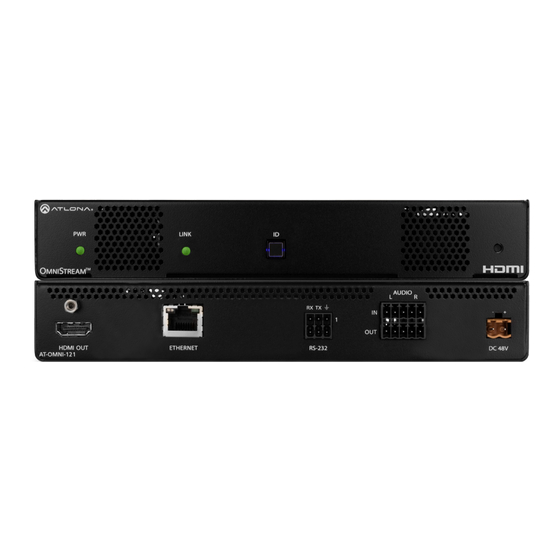
Panel Description AT-OMNI-121 LINK LINK TREAM Front AUDIO TREAM RX TX AUDIO RX TX ETHERNET RS-232 HDMI OUT DC 48V AT-OMNI-121 ETHERNET RS-232 HDMI OUT DC 48V AT-OMNI-121 Rear HDMI OUT This LED indicator is green when the unit is Connect an HDMI cable from this port to a UHD/ powered and booted. -
Page 14: At-Omni-122
Panel Description AT-OMNI-122 LINK TREAM LINK Front TREAM RX TX RX TX HDMI OUT ETHERNET RS-232 AUDIO DC 48V AT-OMNI-122 HDMI OUT ETHERNET RS-232 DC 48V AUDIO AT-OMNI-122 Rear ETHERNET 1 / ETHERNET 2 This LED indicator is green when the unit is Connect Ethernet cables from these ports to the powered and booted. -
Page 15: Installation
Installation External Power (Optional) OmniStream decoders are powered by PoE (Power over Ethernet), when connected to a PoE-capable switch. If a PoE-switch is not used, then the optional 48 V power supply (Atlona part no. AT-PS-48083-C) can be purchased, separately. Insert the positive and negative leads, from the power supply, into the terminals of the 2-pin captive screw connector block, as shown. -
Page 16: Rs-232 Connections
Installation RS-232 Connections Both the AT-OMNI-121 and AT-OMNI-122 provide RS-232 over IP, allowing communication between an automation system and an RS-232 device. This step is optional. Only port 1 can be used for serial data. 1. Use wire strippers to remove a portion of the cable jacket. 2. -
Page 17: Ir Connections
Installation IR Connections The same port that provides RS-232 connections also supports bidirectional IR pass-through, allowing a device to be controlled from either the headend or the decoder endpoint. This step is optional. Refer to Device Control (page for more information. IR emitter configuration Push tab to unlock... -
Page 18: Audio Connectors
Installation Audio Connectors In addition to passing audio directly from the encoder to the decoder, both the AT-OMNI-121 and AT-OMNI-122 provide two additional audio options. Either option can be used or they can be used simultaneously. • HDMI audio can be de-embedded and output to two-channel analog audio. •... - Page 19 Installation AT-OMNI-122 Use the top 5 pins to connect audio input sources. Use the bottom five pins to connect to audio output devices. 1. Use wire strippers to remove a portion of the cable jacket. 2. Locate the included Phoenix block connectors. Press the orange tab, above the terminal, while inserting the exposed wire.
-
Page 20: Connection Instructions
Installation Connection Instructions 1. Connect an Ethernet cable from the ETHERNET port on the decoder to a PoE-capable switch on the Local Area Network (LAN). If using the dual-channel decoder, connect a separate Ethernet cables to ETHERNET 1 and ETHERNET 2 ports. IMPORTANT: If a PoE-capable switch is not available, then the 48V DC power supply (sold separately) must be connected to the decoder. -
Page 21: Connection Diagram
Installation Connection Diagram Source M NI AT-OMNI-111 Display PoE Network Switch M NI AT-OMNI-121 AT-OMNI-121 / AT-OMNI-122... -
Page 22: Getting Started
Getting Started ID Button The ID button serves two functions: 1. Sends a broadcast message, over the network, to any devices that may be listening. 2. Resets the decoder to factory-default settings. NOTE: Some older hardware revisions do not have an ID button. LINK TREAM RX TX... -
Page 23: Resetting To Factory-Defaults
Getting Started Resetting to Factory-Defaults WARNING: Performing a factory-default reset will erase all user-programmed settings from the decoder. IP settings are not preserved. Using the ID button 1. Press and hold the ID button for approximately 30 seconds. 2. The LED indicators on the front panel will flash, then turn “off.” 3. -
Page 24: Led Indicators
Getting Started LED Indicators The following table provides a listing of front-panel LED indicators and their status: Description • If using a PoE switch, make sure that the port on the switch that is connected to the decoder, has PoE enabled. When the decoder is powered using PoE, the PWR indicator will be green. -
Page 25: Accessing The Web Server
Getting Started Accessing the Web Server In order to access the web server of the desired encoder/decoder, the IP address of the encoder must be known. This can be accomplished by using any of the following methods: 1) Running IP scanner software or 2) accessing the encoder using the domain name. -
Page 26: Basic Configuration Tutorial
Basic Configuration Tutorial This section provides a tutorial on configuring two AT-OMNI-111 single-channel encoders and one AT-OMNI-121 single-channel decoder. Make sure the encoders are connected to a source device and that the decoder is connected to a display. Both encoders and the decoder should be connected to the same local network. Refer to Connection Instructions (page 20) for more information. -
Page 27: Setting The System Mode
Basic Configuration Tutorial Setting the System Mode OmniStream offers three system modes. These modes will determine the codec and settings available in OmniStream. 1. Login to each encoder and click System Information in the menu bar. 2. Click the System mode drop-down list and select VCx. This mode will provide access to all of OmniStream 2.0 features. -
Page 28: Configuring Inputs
Basic Configuration Tutorial Configuring Inputs The Input page is used to verify that the encoder recognizes the source device. This page is also used to set the EDID, HDCP version, and provides detailed information about the source signal. The following procedure should be performed on both AT-OMNI-111 encoders. - Page 29 Basic Configuration Tutorial 6. The Video section provides information about the input signal: color depth, subsampling, color space, resolution, frame rate, and HDR (High Dynamic Range). If the HDR indicator is green, this will indicate that HDR content is being transmitted from the source device.
-
Page 30: Encoder Settings
Basic Configuration Tutorial Encoder Settings The Encoding page is used to assign an input to an encoder. In addition, this page allows video settings, such as the maximum bit rate, bit depth, and chroma subsampling to be set. Video thumbnails of the source device can also be displayed on this page. -
Page 31: Creating A Session
Basic Configuration Tutorial Creating a Session Before the video and audio (if any) can be sent out over the network, a session must be created on the encoder. The session assigns each stream to a unique multicast IP address and UDP port assignment. Sessions are always created on encoders. - Page 32 Basic Configuration Tutorial Table 2.1 - Recommended multicast IP address for video, audio, and data streams. Stream Video Audio Data (Control) 226.0.0.1 226.0.10.1 226.0.20.1 First source 226.0.0.2 226.0.10.2 226.0.20.2 Second source 226.0.0.n 226.0.10.n 226.0.20.n nth source Table 2.2 - Recommended UDP ports for video, audio, and data streams. Stream Video Audio...
-
Page 33: Subscribing To An Encoder
Basic Configuration Tutorial Subscribing to an Encoder The next step is to configure the decoder so that it is able to receive video, audio, and/or data (control) streams from the encoder. This process is referred to as “subscribing to the encoder”. Video Configuration 1. -
Page 34: Audio Configuration
Basic Configuration Tutorial Audio Configuration 1. Locate the Input 3 window group and verify that the Enable toggle switch is enabled. When enabled, the toggle switch will be orange. Perform the same procedure for the Input 4 window group. 2. Under the Input 3 window group, enter 226.0.10.1 in the Multicast address field. Under the Input 4 window group, enter 226.0.10.2 in this field. -
Page 35: Configuring The Hdmi Output Stream
Basic Configuration Tutorial Configuring the HDMI Output Stream 1. Click HDMI Output in the menu bar. 2. The Descrambling > Enable toggle switch is enabled by default. When enabled, this toggle will be orange. For this example, leave the setting enabled. 3. - Page 36 Basic Configuration Tutorial 6. Scroll down to the Audio > Input field and select the desired audio stream. Referring to Table 2.3 (shown below), the audio stream that is associated with encoder 1 is Input 3. Therefore, ip_input3 (226.0.10.1:1100) is selected.
- Page 37 Basic Configuration Tutorial Figure 3.1 - Basic OmniStream setup with Decoder #1 subscribed to Encoder Encoder #2 Session 1 Destination IP Address (Video): 226.0.0.2 on so G am UDP Port (Video): 1000 Destination IP Address (Audio): 226.0.10.2 Gaming Console UDP Port (Audio): 1100 AT-OMNI-111 Laptop...
-
Page 38: Troubleshooting
Basic Configuration Tutorial Troubleshooting If no video and/or audio is present on the display, check the following for both Encoder #1 Encoder unless otherwise noted. Encoder Checklist • Verify that all encoders and decoders are set to the same system mode. In this tutorial, both encoders and the decoder should be set to VCx. -
Page 39: Decoder Checklist
Basic Configuration Tutorial Decoder Checklist • Verify that all encoders and decoders are set to the same system mode. In this tutorial, both encoders and the decoder should be set to VCx. Refer to Setting the System Mode (page 27). •... -
Page 40: Device Operation
Device Operation Device Control Downstream Control using RS-232 Control using RS-232 is converted and transmitted over IP by the encoder. Destination devices can either be the IP address of a display or a decoder. 1. Login to the encoder and click the Serial menu. 2. - Page 41 Device Operation 6. Click the Session menu. 7. Under the desired Session, locate the AUX section and click the Source drop-down list to select the desired serial port. 8. Click the Enable toggle switch to display the additional fields. 9. Enter the destination IP address and UDP port in the Destination IP address and Destination UDP port fields, respectively.
- Page 42 Device Operation 11. Login to the decoder and click the IP Input menu. 12. Locate an Input that does not contain a defined Multicast address field. In this example, Input 5 will be used. Note that if a multicast address was used in Step 9, then that multicast address must be entered in the Multicast address field under Input 5.
-
Page 43: Control Using Tcp Proxy
Device Operation 18. Under the Serial configuration window group, click the Port drop-down list and select the desired port. 19. Click the Mode drop-down list and select output. 20. Click SAVE. Control using TCP Proxy TCP/IP traffic received by an encoder or decoder, on the defined IP:Port socket, are translated to RS-232, allowing both control of source or display. - Page 44 Device Operation 4. Under the Serial Configuration window group, click the Port drop-down list and select the desired serial port. 5. Click the Mode drop-down list and select tcpproxy. 6. Click the TCPProxy > Interface drop-down list and select the desired Ethernet interface. 7.
-
Page 45: Downstream Control Using Triggering
Device Operation Downstream Control using Triggering TCP/IP traffic received by an encoder or decoder, on the defined IP:Port socket, are translated to RS-232, allowing both control of source or display. Control is achieved using a control system, where all control commands are stored. Option 1: Defining Commands on the Decoder 1. - Page 46 Device Operation 8. For each of the available commands, click the Mode drop-down list and select raw. The available commands are: Display On, Display Off, Volume Up, and Volume Down. 9. Enter the command data in either ASCII or hexadecimal format using the ASCII or HEX fields. 10.
- Page 47 Device Operation Option 2: Defining Commands on the Encoder 1. Login to the encoder and click the Serial menu. 2. For each of the available commands, click the Interpret on drop-down list and select decoder. The available commands are: Display On, Display Off, Volume Up, and Volume Down. NOTE: Setting the Interpret on drop-down list to encoder implies that commands are defined/ stored on the encoder.
- Page 48 Device Operation 5. Click the Session menu. 6. Under the desired Session, locate the AUX section, click the Source drop-down list, and select Commands. 7. Click the Enable toggle switch to display the additional fields. 8. Enter the destination IP address and UDP port, of the decoder, in the Destination IP address and Destination UDP port fields, respectively.
- Page 49 Device Operation 14. Click the Serial menu. 15. Under Serial port configuration, set the Mode drop-down list to serial. 16. Click the SAVE button. 17. Under Serial configuration, select the desired port. 18. Click the Mode drop-down list and select output. 19.
-
Page 50: Upstream Control Using
Device Operation Upstream Control using RS-232 The serial interface provides RS-232 control of both downstream and upstream devices. Source control is provided by enabling bidirectional communication. 1. Login to the decoder and click the Serial menu. 2. Under the Serial Port Configuration window group, click the Mode drop-down list and select Serial. 3. - Page 51 Device Operation 8. Enter the destination IP address (the IP address of the encoder) and UDP port in the Bidirectional > Destination IP address and Bidirectional > Destination UDP port field, respectively. 9. Click the Bidirectional > Enabled toggle switch to the enabled position.
-
Page 52: Upstream Control Using Ir
Device Operation 20. Click the AUX > Bidirectional toggle switch to enable it. When enabled, the toggle switch will be orange. 21. Click the SAVE button. Upstream Control using IR To control of headend source from downstream, refer to the Upstream Control using RS-232 (page 50) instructions. -
Page 53: Fast Switching
Device Operation Fast Switching The VCx codec provides fast switching at resolutions up to 4K YUV 4:4:4 @ 60 Hz. This is an improvement over the VC-2 codecs that limited fast switching up to 1920x1200. When the decoder resolution and frame rate are set to Auto, VCx fast switching operates at the preferred resolution and frame rate of the display. -
Page 54: Fast Switching Faqs
Device Operation Fast Switching FAQs Question: Does fast switching work between streams of different resolutions? Answer: Yes. Fast switching can be used between streams with different resolutions and frame rates. Question: Does fast switching work between HDR and SDR streams? Answer: Yes, fast switching can be used between HDR and SDR streams;... -
Page 55: Multiview Nomenclature
Device Operation Multiview Nomenclature General Overview A multiview is comprised of a canvas (display area) containing at least two, but no more than four subframes, where each subframe has the following parameters: NOTE: Multiview cannot be used in conjunction with fast switching and/or with video walls. DEFINITIONS: Subframe - The stream multicast IP address for the video. -
Page 56: Anchor Points
Subframe 1 Subframe 1 3840 x 2160 3840 x 2160 Anchor Point Subframe 2 Subframe 2 640 x 360 Device Operation 640 x 360 Anchor Point If the incoming stream changes resolution to 1280x720, then the subframe will grow in size, but it will still fit on- screen, because its bottom right Anchor point has not changed position. -
Page 57: Multiview And Dual-Streaming Tutorial
Device Operation Multiview and Dual-Streaming Tutorial This section provides a tutorial on configuring a multiview setup. In addition, the concept of dual-streaming will be introduced. Review the diagram and the table below for a summary of how this setup will function. All encoders and the decoders should be connected to the same local network. -
Page 58: Dual-Streaming Encoder Configuration
Device Operation Dual-Streaming Encoder Configuration Encoder #1 This encoder is used with the HD camera and will be configured to dual-stream 1080p and 720p. 1. Go to the System information page, click the System mode drop-down list and select VCx. Click the SAVE button to commit changes. - Page 59 Device Operation Encoder #2 This encoder is used with a 4K source and will be configured to dual-stream 4K and 1080p. 1. Go to the System information page, click the System mode drop-down list, and select VCx. Click the SAVE button to commit changes.
-
Page 60: Decoder Configuration
Device Operation Decoder Configuration Dual-streaming has been successfully configured on both encoders. This provides a total of four streams which are listed in the tables, below, for reference. Encoder #1 (source: HD camera) Stream Encoder Resolution Session Multicast IP Address Port 1920x1080 226.0.0.1... -
Page 61: Multiview Configuration
Device Operation Multiview Configuration The final step is to configure the decoders to display the proper stream(s), as outlined in the tutorial diagram (shown below). Encoder #2 Laptop AT-OMNI-111 HD camera Decoder #3 AT-OMNI-111 Encoder #1 Decoder #2 PoE Network Switch AT-OMNI-121 AT-OMNI-121 Display... - Page 62 Device Operation 9. Click the SAVE button. 10. Click HDMI Output in the menu bar. 11. Locate the Video section, click the Input drop-down list, and select Multiview pip. This is the name of the multiview that was created in Step 4. The name Multiview will always be used as a prefix, indicating that the selection is a multiview.
-
Page 63: Positioning Subframes
Device Operation Positioning Subframes Each subframe in a multiview can be repositioned on the screen based on its anchor point. The anchor point (0,0) represents the top left corner of the multivew canvas. For example, in the picture-in-picture example that was created on Decoder #1, the settings for each subframe are as follows:... -
Page 64: Changing The Z-Order
Device Operation Changing the Z-Order The ordering of overlapping subframes in two-dimensional space is referred to as the z-order. In the illustration below, the red window is set to priority 4 and will be displayed on top of all other subframes. Assigning a subframe to z-order 1 (the blue window) will move the subframe behind the other subframes. -
Page 65: Adding Subframes
Device Operation Adding Subframes Multiview supports a maximum of 4 subframes. As long as the maximum number of subframes is not exceeded, additional subframes can be added. This provides for customization of existing layouts. 1. Click the Multiview menu. 2. Under the Multiviews window group, click the name of the Multiview to be changed. 3. -
Page 66: Configuring Audio Output
Device Operation Configuring Audio Output IMPORTANT: When using analog audio inputs on the OmniStream decoder, the decoder must be powered using the 48V power supply (AT-PS-48083-C). This power supply is sold separately and can be purchased from Atlona. In addition to passing audio directly from the encoder to the decoder, both the AT-OMNI-121 and AT-OMNI-122 provide two additional audio options •... -
Page 67: Aes67 Audio
Device Operation AES67 Audio AES67 audio is a standard for high-performance audio streaming over IP, providing several features such as synchronization, media clock identification, and connection management. AES67 does not support bitstream/ compressed audio formats, such as Dolby® Digital, and others. Source audio must be transmitted as LPCM up to eight channels at 192 kHz / 24-bit. - Page 68 Device Operation 6. Go to the decoder and click the SAP Listener menu. 7. Click the Enable toggle switch to enable the SAP listener. When enabled, the toggle switch will be orange. 8. Click the SAVE button. 9. Click the IP Input menu. 10.
- Page 69 Device Operation 13. Click the HDMI Output menu. 14. Locate the Audio section, click the Audio > Input drop-down list, and select the input that was configured in Steps 10 and 11. 15. Click the Enable AES67 toggle switch to enable it. When enabled, the toggle switch will be orange. 16.
-
Page 70: Descrambling
Device Operation Descrambling OmniStream supports 128-bit Advanced Encryption Standard (AES) scrambling and is required for HDCP-encrypted video streams. Scrambling can be enabled or disabled and is applied to individual sessions. In order to function properly, scrambling must be enabled on the encoder and descrambling must be enabled on the decoder. The scrambling and descrambling key on both the decoder and all subscribed encoders must be identical. -
Page 71: Slate / Logo Insertion
Device Operation Slate / Logo Insertion The difference between a “slate” and “logo” is in the size of the image and how it is used: Logos are classified as smaller, low-resolution images that can be positioned at specified locations on the screen. Slates occupy the entire screen. -
Page 72: Deleting Slates
Device Operation 14. Click Encoding in the menu bar. 15. Click the Slate mode drop-down list, and select Off, Manual, or Auto. Slate mode Description Disables the image from being displayed. Manual The image will always be displayed, superimposed on the source signal, and will remain even if the source signal is lost. -
Page 73: Text Insertion
Device Operation Text Insertion Text can be inserted and scrolled across the screen, making it useful for messages and notifications. Several options are available when using text: Scroll speed adjustment (forward, reverse, or static), number of iterations, text color, vertical / horizontal position, as well as transparency. 1. -
Page 74: Configuring A Static Ip Address
Device Operation Configuring a Static IP Address There will be situations where it is desirable for the encoder to be assigned a static IP address. Some IT environments prefer this method, as opposed to having a DHCP server dynamically assign IP addresses. If the decoder is unable to detect a DHCP server within 15 seconds, then Automatic Private IP Addressing (APIPA) will be used to assign the encoder an address within the IPv4 address block 169.254.xxx.xxx/16. -
Page 75: 802.1X Authentication
Device Operation 802.1X Authentication 802.1X is a server-based port authentication which restricts unauthorized (rogue) clients from connecting to a Local Area Network. In its simplest form, 802.1X usually involves three parties: supplicant (client device), authenticator (Ethernet switch or WAP), and an authentication server. Before the device is permitted on the network, port communication is restricted to Extensible Authentication Protocol over LAN (EAPOL) traffic. - Page 76 Device Operation 1. Login to the decoder and click the NETWORK menu. 2. Click the 802.1x > Mode drop-down list, at the bottom of the Network window group and select the desired authentication method. In the example below, PEAP/MSCHAPv2 is selected. Once a method is selected, the required fields for that method will be displayed.
-
Page 77: Creating Video Walls
Device Operation Creating Video Walls Introduction Before proceeding with creating video walls, review the tables below. These tables provide information on video wall size, maximum timing, color space, and bit depth. NOTE: OmniStream video walls do not support interlaced sources. The following table lists the maximum video wall size, based on the resolution of the source. -
Page 78: Landscape Mode
Device Operation Landscape Mode The following diagram will be used to illustrate how to configure a 2 x 2 video wall. The details of this diagram are listed below: • Four decoders are subscribed to a single encoder. Each decoder is connected to a display. •... - Page 79 Device Operation Note that the order in which each image is cropped, scaled, and/or rotated is arbitrary. In this example, the configuration process will begin with Display 1, in the top left. 1. Login to the decoder and click the HDMI Output menu. 2.
- Page 80 Device Operation 7. Enter the starting coordinates of the portion of the source stream that will be displayed on this decoder in the Horizontal and Vertical fields.. These values are the pixel start position (upper left most pixel). The table below lists left and right coordinates for a 2x2 video wall, with the specified source resolution.
- Page 81 Device Operation 9. Click the SAVE button at the bottom of the screen to commit changes. 10. Repeat steps 3 through 9 for decoders 2, 3, and 4. Note that in the example below, decoders 3 and 4 will not require any rotation.
-
Page 82: Portrait Mode
Device Operation Portrait Mode IMPORTANT: Portrait Mode is only supported on single-channel decoders. Images can be rotated 90° or 270° to create portrait-oriented video walls. The steps to configure portrait-oriented video walls is very similar to creating landscape video walls. A similar scenario to the landscape video wall challenge will be used to illustrate how to configure a 1 x 4 portrait- oriented video wall. - Page 83 Device Operation 1. Login to the decoder and click HDMI Output in the menu. 2. Under the Video section, click the Stretch/Crop Mode drop-down list and select Full Screen. This guarantees that the image will fill the screen. 3. Click the Resolution drop-down list and select 1920x1080.
- Page 84 Device Operation 7. Enter the starting coordinates of the portion of the source stream that will be displayed on this decoder in the Horizontal and Vertical fields. These values are the pixel start position (upper left most pixel). The table on the next page lists left and right coordinates for a 1x4 video wall, with the specified source resolution.
- Page 85 Device Operation NOTE: 0 and 180 used for landscape mode video walls and 90 and 270 for portrait mode. Refer to Portrait Mode (page 82) for more information. Table listing width and height examples for 1x4 video wall. Source resolution Width (pixels) Height (pixels) 3840 x 2160 (UHD)
- Page 86 Device Operation 10. Repeat steps 3 through 9 for decoders 2, 3, and 4. Since display 2 and 3 were mounted upside-down, they will require a rotation of 180° (to flip horizontally) + 90° (to align them as portrait), giving a total rotation of 270°. IMPORTANT: When using dual-channel decoders, the Rotation feature can only be used when a single HDMI channel is active.
-
Page 87: Bezel Compensation
Device Operation Bezel Compensation Displays have a region where video is not displayed, called the bezel. This can cause display issues when creating video walls. Bezel compensation takes this area into account when a single video source is mapped across multiple displays. -
Page 88: Configuring Redundant Streams
Device Operation Configuring Redundant Streams OmniStream decoders have the ability to identify missing streams. Should an input be disconnected from the encoder, the image will recover almost instantaneously. The decoder can access the same stream from two separate multicast addresses and switch between them, when necessary. 1. -
Page 89: Configuration And Management Interfaces
Configuration and Management Interfaces Web Server NOTE: This section assumes that the System mode is set to VCx. If VC-2 Video or VC-2 PC Application is used, some features on these pages will not be available. System information page Firmware version The version of firmware that the decoder is running. - Page 90 Configuration and Management Interfaces Description Provides the option of assigning descriptive name to the unit. Location Provides the option of assigning a description of where the unit is located. Timezone Displays the time zone format. Click the SET TIMEZONE button, to assign the time zone. Date/Time Displays the current date and time.
- Page 91 Configuration and Management Interfaces FACTORY RESET Click this button to reset the decoder to factory-default settings. When performing a factory reset, the following options can be selected, by clicking the check box. If no options are selected, then the decoder is reset with no factory-default settings.
-
Page 92: Sap Listener Page
Configuration and Management Interfaces SAP Listener page Enable Click this toggle to enable or disable SAP. This feature is enabled when the toggle switch is orange. This is the default setting. If an SAP announcement is picked up, it will be displayed below the SAP window group (as shown here). -
Page 93: Ip Input Page
Configuration and Management Interfaces IP Input page Input window groups Name Multicast filter (IGMPv3) > Addresses The name of the input. This field cannot be changed. Enter the desired address(es) in this field. Separate multiple multicast IP addresses with a comma delimiter. Enable Click this toggle switch to enable or disable the IP input. -
Page 94: Multiview Page
Configuration and Management Interfaces Multiview page This page is only availble if the System mode is set to VCx. Refer to NOTE: Setting the System Mode (page 27) for more information. ADD MULTIVIEW If a multiview has not been configured, this will be the only button displayed on this page. - Page 95 Configuration and Management Interfaces Multiview window group Each multiview that is created will have its own window group. The following are common to each window group. Resolution The resolution of the multivew canvas. Background color The background color is set using RGB values between 0 and 255.
- Page 96 Configuration and Management Interfaces SAVE Click this button to commit changes to the Width, Height, and Background color fields in the multiview window group. # of subframes Displays the number of subframes within a multiview configuration. Subframe [position] This is the name of the subframe. If default layouts are used, the default subframe names are the positions of the subframe in the multiview.
-
Page 97: Serial Page
Configuration and Management Interfaces Serial page Serial port configuration window groups The following fields apply to both Serial port configuration window groups. Name Parity Click this drop-down list to select the parity bit: None, The name of the serial port. This field cannot be Odd, Even, Mark, or Space. - Page 98 Configuration and Management Interfaces Serial configuration window groups The following fields apply to both Serial configuration window groups. Name The name of the port. This field cannot be changed. Port Click this drop-down list to select the desired serial port. Mode Click this drop-down list to select the desired control mode.
-
Page 99: Hdmi Output Page
Configuration and Management Interfaces HDMI Output page Output window groups Dual-channel decoders have two Output window groups and the following fields apply to both Output window groups. Name The name of the output port. This field cannot be changed. Enable Click this toggle switch to enable or disable scrambling. - Page 100 Configuration and Management Interfaces Encrypted This indicator will be green if the HDMI output is HDCP- encrypted. Version Click this drop-down list to select the supported version of HDCP. Negotiated Displays the version of HDCP negotiated with the connected sink. EDID This field will display the EDID of the connected display.
- Page 101 Configuration and Management Interfaces This indicator will be green if the HDMI output video contains HDR content. Stretch / Crop Mode Click this drop-down list to select the aspect ratio. Mode Description Keep Aspect Ratio Aspect ratio is preserved; the output on the decoder will be the same as the input on the encoder.
- Page 102 Configuration and Management Interfaces Video Wall > Enable Click this toggle switch to enable or disable the video wall option. Refer to Creating Video Walls (page 77) for more information on using video walls. Video Wall > Unit Click this drop-down list to specify the units. Available options are pixels, mm, and inches.
- Page 103 Configuration and Management Interfaces TO PRIMARY Click this button to assign as the Primary IP Input. Both Video and Audio support this feature. TO BACKUP Click this button to force the audio stream to fall over to the Backup IP Input (if redundancy is configured). Both Video and Audio support this feature.
- Page 104 Configuration and Management Interfaces Volume Click the speaker icon on the left to decrease volume. Click the speaker icon on the right to increase volume. Range: 0 to 15. Analog Power (indicator) This indicator will be green when the decoder is powered by the optional external 48 V DC power supply.
-
Page 105: Logo Page
Configuration and Management Interfaces Logo page New logo window group Name Enter a name for the logo in this field. Choose File Click this button to select the logo file to be uploaded. Files must be in .png or .svg format and must not exceed 5 MB (5120000 bytes) in size. - Page 106 Configuration and Management Interfaces Horizontal (%) Enter the horizontal position of the logo based on the resolution of the video stream. Vertical (%) Enter the vertical position of the logo based on the resolution of the video stream. Width (%) Enter the width of the logo.
-
Page 107: Text Page
Configuration and Management Interfaces Text page Text insertion window groups The following fields apply to both Text insertion window groups and is based on how many decoding channels there are. The AT-OMNI-122 will have two Text Insertion window groups. Target Displays the name of the output where the text will appear. - Page 108 Configuration and Management Interfaces Horizontal Enter the horizontal position of the text, based on the resolution of the video stream. Vertical Enter the vertical position of the text, based on the resolution of the video stream. Width Enter the width of the text. This value is based on the horizontal resolution of the video stream.
-
Page 109: Network Page
Configuration and Management Interfaces Network page Network window groups The following fields apply to both Network window groups. The single-channel decoder will only have one Network window group. Name Displays the name of the Ethernet interface. This field cannot be changed. Enabled This indicator displays the state of the Network Interface Card (NIC). - Page 110 Configuration and Management Interfaces Link speed Displays the Ethernet interface link speed in Mbps. This field cannot be modified. MAC address Displays the MAC address of the Ethernet interface. Telnet Enable Click this toggle switch to enable or disable Telnet. If disabled, then Telnet sessions to the decoder cannot be established.
-
Page 111: Ptp Page
Configuration and Management Interfaces PTP page The PTP page provides options for adjust Precision Time Protocol (PTP) for AES67 audio streams. PTP is used by AES67 to keep all audio streams synchronized. For a system utilizing PTP, all devices undergo an automatic self-election process to choose the device to be used as the PTP grandmaster (GM) clock, based on the accuracy of the device’s clock and the device’s configured priority. - Page 112 Configuration and Management Interfaces Displays the TTL value. The default IPV4 TTL value used for PTP is 8. Is GM If the indicator is green, then this interface is the PTP GM. GM Identity The grandmaster clock identity. Master Offset Displays the grandmaster clock offset.
-
Page 113: Lldp Page
Configuration and Management Interfaces LLDP page The Link Layer Discovery Protocol (LLDP) page returns information about the switch that is connected to the decoder. NOTE: LLDP must be enabled on the switch that the decoders are connected to, in order for the switch information to be displayed. -
Page 114: Configuration Page
Configuration and Management Interfaces Configuration page Import configuration Choose File Click this button to select the desired configuration file to be uploaded. IMPORT Click this button to upload the selected configuration file to the encoder. The hostname, specific to the configuration filename, will be ignored. -
Page 115: Users Page
Configuration and Management Interfaces Users page User window groups The following fields apply to all User window groups. Username Enter the desired username in this field. Role Click this drop-down list to select the desired role of the user. Available options are: administrator, operator. New password Enter the desired password for the username in this field. -
Page 116: License Page
Configuration and Management Interfaces License page This page displays all installed licenses and allows additional licenses to be installed. License info window group This window group lists all installed licences, along with the key code and request codes INSTALL LICENSE Click this button to validate and install the license. -
Page 117: Upgrade Page
Configuration and Management Interfaces Upgrade page This page is used to update the firmware on the decoder. Upgrade window group Choose File Click this button to select the firmware file to be uploaded. UPLOAD Click this button to upload the selected firmware file. AT-OMNI-121 / AT-OMNI-122... -
Page 118: Appendix
Appendix Updating the Firmware Follow the procedure below to update OmniStream units using the built-in web server. 1. Launch the desired web browser and enter the IP address of the encoder/decoder in the address bar. 2. Enter the username and password. Note that the password field will always be masked. The default credentials are: admin Username:... -
Page 119: Performing A Link Test
Appendix Performing a Link Test Follow the procedure below to perform a link integrity test between an encoder and decoder(s). 1. Launch a web browser and enter the IP address of the encoder in the address bar. 2. Open another tab in the browser and enter the IP address of the subscribing decoder in the address bar. 3. - Page 120 Appendix 6. An orange screen with a progress bar will be displayed during the testing procedure. 7. After the test, the encoder web page will automatically redirect to the Notifications tab where the user can see the results. If the test passed, information similar to the following will be displayed. Note the information in the Description field: “100% of packets received by ...”...
- Page 121 Appendix If the test fails, it could be that less than 100% of packets are received, indicating connectivity, but with some amount of packet loss. If it shows “No one replied!” or if the target decoder is not shown in results, it could indicate that there is a connectivity issue or that the decoder is not subscribed to the correct video multicast address.
-
Page 122: Fec Details
Appendix FEC Details Matrix Size, Overhead, and Latency • FEC can only work if a single packet from each row/column is missing. Multiple packets missing from each row/ column will cause FEC to fail. • Due to the above, a smaller matrix is more robust, as there is a better chance of errors not occurring in the same row/column. -
Page 123: Fec, Latency, And Lip Sync
Appendix FEC, Latency, and Lip Sync • In order for FEC to work, the matrix must be filled in order to calculate the FEC packets. This introduces some additional latency. Due to high bitrates, this is not noticeable for video, but can be very significant for audio. Therefore, Atlona recommends either leaving FEC disabled for audio or using a very small matrix. -
Page 124: Mounting Instructions
Appendix Mounting Instructions OmniStream decoders includes two mounting brackets 6. Mount the unit using the oval-shaped holes, on each and four mounting screws, which can be used to attach rack ear. If using a drywall surface, a #6 drywall the unit to any flat surface. screw is recommended. -
Page 125: Rack Tray For Omnistream
Appendix Rack Tray for OmniStream OmniStream decoders can also be mounted in the OmniStream rack tray (AT-OMNI-1XX-RACK-1RU). The rack tray is sold separately and provides easy mounting and organization of up to two OmniStream encoders/decoders in a convenient 1U rack tray. The OmniStream rack tray can be purchased directly from Atlona. 1. -
Page 126: Specifications
Appendix Specifications Single-Channel Decoder Video Signal HDMI Copy Protection HDCP 2.2 UHD/HD/SD 4096×2160 (DCI) @ 30/24 Hz 1280x720p @ 30/50/59.94/60 Hz 3840×2160 (UHD) @ 60/50/24/25/30 Hz 720x576p @ 50 Hz 1920x1080p @ 23.98/24/25/29.97/30/50 720x576i @ 25 Hz /59.94/60 Hz 720x480p @ 59.94/60 Hz 1920x1080i @ 25/29.97/30 Hz 720x480i @ 29.97/30 Hz... - Page 127 Appendix Audio Pass-through LPCM 2.0 Dolby Digital Dolby Atmos ® ® LPCM 5.1 Dolby Digital Plus ® LPCM 7.1 Dolby TrueHD DTS-HD Master Audio ™ Down-mixing Multichannel LPCM to two-channel LPCM Sample Rate 32 kHz, 44.1 kHz, 48 kHz, 88.2 kHz, 96 kHz, 176.4 kHz, 192 kHz Bit Depth Up to 24-bit Analog audio...
- Page 128 Appendix Indicators and controls 1 - LED, tricolor (red, amber, green) LINK 1 - LED, bicolor (red, green) 1 - Momentary, tact-type, backlit (blue); sends an identification broadcast message over the network to any listening devices. Reboot 1 - Momentary, tact-type Power IEEE 802.3af Consumption...
- Page 129 International atlona.com 408.962.0515 41.43.508.4321 • • 35302-R15...
Need help?
Do you have a question about the ATLONA OmniStream AT-OMNI-121 and is the answer not in the manual?
Questions and answers