Panduit ATLONA OmniStream AT-OMNI-512 Manual
R-type dual-channel networked av encoder
Hide thumbs
Also See for ATLONA OmniStream AT-OMNI-512:
- Manual (96 pages) ,
- Installation manual (9 pages) ,
- Manual (68 pages)

Related Manuals for Panduit ATLONA OmniStream AT-OMNI-512


Summary of Contents for Panduit ATLONA OmniStream AT-OMNI-512
- Page 1 OmniStream R-Type ™ Dual-Channel Networked AV Encoder Atlona Manuals AT-OMNI-512 Networked AV...
- Page 2 Version Information Version Release Date Notes Mar 2017 Initial release Jul 2018 Includes updates to 1.2.1 firmware Aug 2019 Documentation updated to support AMS 2.4.0 Sep 2019 Documentation updated to support OmniStream 1.2.5; various bug fixes. Feb 2020 Added web server documentation reflecting changes to 1.2.6 firmware. Refer to the release notes for a complete listing features and bug fixes.
- Page 3 Welcome to Atlona! Thank you for purchasing this Atlona product. We hope you enjoy it and will take a extra few moments to register your new purchase. Registration only takes a few minutes and protects this product against theft or loss. In addition, you will receive notifications of product updates and firmware.
- Page 4 Atlona, Inc. (“Atlona”) Limited Product Warranty Coverage Atlona warrants its products will substantially perform to their published specifications and will be free from defects in materials and workmanship under normal use, conditions and service. Under its Limited Product Warranty, Atlona, at its sole discretion, will either: •...
- Page 5 Atlona, Inc. (“Atlona”) Limited Product Warranty • Damage, deterioration or malfunction resulting from the installation or removal of this product from any installation, any unauthorized tampering with this product, any repairs attempted by anyone unauthorized by Atlona to make such repairs, or any other cause which does not relate directly to a defect in materials and/or workmanship of this product.
- Page 6 Important Safety Information 9. Do not defeat the safety purpose of a polarized CAUTION or grounding-type plug. A polarized plug has two RISK OF ELECTRIC SHOCK blades with one wider than the other. A grounding DO NOT OPEN type plug has two blades and a third grounding CAUTION: TO REDUCT THE RISK OF prong.
-
Page 7: Table Of Contents
Table of Contents Introduction Features Package Contents Panel Description Installation RS-232 Connections IR Connections Connection Instructions Connection Diagram Configuration Accessing Encoders in AMS Configuring a Static IP Address Input Selection Input Selection Verifying the Input Session Configuration Basic Operation LED Indicators ID Button Broadcast Messaging Reset to Factory-Default Settings. - Page 8 Table of Contents Web Server Accessing the Web Server Getting the IP Address Logging In System information page Input page EDID page Encoding page Serial page Session page Logo page Text page Network page PTP page LLDP page Configuration page Users page License page Upgrade page...
-
Page 9: Introduction
Introduction The Atlona OmniStream™ R-Type (AT-OMNI-512) is a networked AV encoder with two independent channels of encoding for two HDMI sources up to UHD @ 60 Hz and HDR, plus embedded audio and RS-232 or IR control pass- through. It is part of the OmniStream R-Type Series, designed for high performance, flexible distribution of AV over Gigabit Ethernet in residential and light commercial applications. -
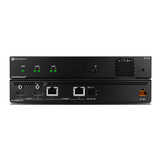
Page 10: Panel Description
Panel Description HDMI LINK HDMI LINK TREAM Front TREAM RX TX RX TX RS-232 / IR HDMI IN ETHERNET DC 48V AT-OMNI-512 HDMI IN ETHERNET RS-232 / IR DC 48V AT-OMNI-512 Rear HDMI IN 1 / HDMI IN 2 This LED indicator glows bright green when the unit Connect HDMI cables from these ports to an HD is powered. -
Page 11: Installation
Installation RS-232 Connections The AT-OMNI-512 provides RS-232 over IP which allows communication between an automation system and an RS- 232 device. This step is optional. Either the top three or bottom three set of terminals can be used for RS-232. 1. -
Page 12: Ir Connections
Installation IR Connections The same port that provides RS-232 connections also supports bidirectional IR pass-through, allowing a device to be controlled from either the headend or the decoder endpoint. This step is optional. Either the top three or bottom three set of terminals can be used for IR. Only the RS-232 2 port (bottom set of connectors) supports both RS-232 and IR. - Page 13 Installation For downstream IR control, either multicast or unicast mode can be used. However, when controlling a source from the decoder (viewing location), unicast mode should be used. Refer to Unicast Mode (page 25) Multicast Mode (page 27) for more information. AT-OMNI-IR-TX SIGNAL GROUND...
-
Page 14: Connection Instructions
Installation Connection Instructions 1. Connect an Ethernet cable from the ETHERNET 1 and ETHERNET 2 ports on the encoder to a PoE-capable switch on the Local Area Network (LAN). Note that if a PoE-capable switch is not available, the 48V DC power supply (sold separately) must be connected to the encoder. -
Page 15: Connection Diagram
Installation Connection Diagram Blu-ray Player Automation Control System CT OR RE SE 48 V M NI AT-OMNI-512 Projector AT-OMNI-521 M NI AT-OMNI-512... -
Page 16: Configuration
Configuration Accessing Encoders in AMS It is recommended that the Atlona Management System (AMS) be used to configure and control OmniStream devices. AMS uses multicast Domain Name Server (mDNS) to automatically discover each encoder on the network. AMS is free and can be downloaded from https://www.atlona.com/ams. By default, the AT-OMNI-512 is set to DHCP mode, allowing a DHCP server (if present) to assign the encoder an IP address. - Page 17 Configuration 6. Click Devices from the fly-out menu. 7. Click the Unassigned option. 8. Click the left and right arrows, at the bottom of the Unassigned list, to scroll through all available devices. Arrow buttons AT-OMNI-512...
- Page 18 Configuration All available encoders will be displayed under the Unassigned category. When an encoder is unassigned, it means that it has not been assigned to a site, building, and/or room. Refer to the AMS User Manual for more information on these topics. If a DHCP server is not found within 60 seconds, the encoder will be placed in Auto IP mode and assigned an IP address within the range of 169.254.xxx.xxx.
- Page 19 Configuration 11. Click SESSION in the top menu bar. 12. Locate the Video section. 13. Delete the value in the Destination Multicast / Unicast Address field. Destination Multicast/Unicast Address field 14. Locate the Audio section and delete the value in the Destination Multicast / Unicast Address field. Destination Multicast/Unicast Address field SAVE button 15.
-
Page 20: Configuring A Static Ip Address
Configuration Configuring a Static IP Address The following section is only required to set the AT-OMNI-512 encoder, currently in Auto IP mode, to a static IP address. If a DHCP server is not found within 60 seconds, encoders are automatically placed in Auto IP mode and will be assigned an IP address within the range 169.254.xxx.xxx. -
Page 21: Input Selection
Configuration Input Selection Once the OmniStream encoder is configured, and can be located on the network, the encoder will need to be instructed on how to handle source devices and to which stream each source is assigned. Input Selection 1. Under AMS, click INPUT in the menu bar. 2. -
Page 22: Session Configuration
Configuration Session Configuration Once the inputs have been assigned to the desired source, the next step is to configure each session. A session is a class-D multicast IP address that is assigned to an AV stream. If each stream is configured for bit rates less than 450 Mbps (only recommended for 1080p and lower resolutions), a single Ethernet cable can transport two sessions. -
Page 23: Basic Operation
Basic Operation LED Indicators The following table provides a listing of front-panel LED indicators and their status: Description • If using a PoE switch, make sure that the port on the switch that is connected to the encoder, has PoE enabled. When the encoder is powered using PoE, the PWR indicator will be green. -
Page 24: Id Button
Basic Operation ID Button The ID button serves two functions: 1. Sends a broadcast message, over the network, to any devices that may be listening. 2. Resets the encoder to factory-default settings. HDMI LINK TREAM RX TX Broadcast Messaging Press and release the ID button to send a broadcast notification over the network to any devices that may be listening. -
Page 25: Unicast Mode
Basic Operation Unicast Mode The term unicast is used to describe a configuration where information is sent from an encoder to a single decoder. Although it is common to have multiple encoder and decoder units within a system, it may also be desirable to restrict a single encoder to communicate with one decoder. - Page 26 Basic Operation 5. Go to the decoder AMS interface. Refer to the OmniStream R-Type Dual-Channel A/V Decoder User Manual, if necessary. 6. Click IP INPUT from the menu. 7. Remove the IP address from the Multicast Address field. 8. Click the SAVE button to commit changes. Field should be blank 9.
-
Page 27: Multicast Mode
Basic Operation Multicast Mode The term multicast is used to describe a configuration where information is sent from one or more points to a set of other points. For example, a single encoder can transmit data to multiple decoders. In addition, if multiple encoders are used, each encoder can stream data to any decoder that is not already receiving data from an encoder. - Page 28 Basic Operation AT-OMNI-512...
-
Page 29: Aes67 Audio
Basic Operation AES67 Audio AES67 audio is a standard for high-performance audio streaming over IP, providing several features such as synchronization, media clock identification, and connection management. AES67 does not support bitstream/ compressed audio formats, such as Dolby® Digital, and others. Source audio must be transmitted as LPCM up to eight channels at 192 kHz / 24-bit. -
Page 30: Edid Management
Basic Operation EDID Management OmniStream encoders provide EDID management for each input. The encoder can be assigned one of several included EDID presets or can be assigned a custom EDID. Raw EDID data can be copied from displays or other sink devices, that are connected to OmniStream decoders. - Page 31 Basic Operation 6. Enter the EDID data in the Raw EDID field. EDID data can be copy and pasted from an EDID editor and must be in hexadecimal format. Commas or spaces can be included as delimiters to separate each hexadecimal value. 7.
-
Page 32: Copying An Edid From The Display
Basic Operation Copying an EDID from the Display In order to allow the source device to send all AV formats that are supported by the display device, the EDID from the decoder must be copied to the encoder. Access to a decoder will be required. 1. - Page 33 Basic Operation 5. Select the desired encoder, within AMS. 6. Click INPUT in the menu bar. 7. Click the EDID drop-down list, in the desired HDMI Input window group. 8. Scroll down to the bottom of the list and select + Add Custom EDID. Add Custom EDID 9.
-
Page 34: Advanced Operation
Advanced Operation Scrambling OmniStream supports 128-bit Advanced Encryption Standard (AES) scrambling and is required for HDCP-encrypted streams. Scrambling can be enabled or disabled through AMS, and can be applied to individual sessions. In order for scrambling to function properly, it must be enabled on both the encoder session and all decoders subscribed to a stream that is a part of a scrambled session. -
Page 35: Using The Virtual Matrix
Advanced Operation Using the Virtual Matrix 1. Access the Virtual Matrix. Refer to The Virtual Matrix (page 57) for more information. 2. Locate the desired encoder or decoder. Scrambling is handled on the encoder; descrambling is handled on the decoder. 3. -
Page 36: Slate / Logo Insertion
Advanced Operation Slate / Logo Insertion Slate / logo insertion is managed from within AMS. The difference between a “slate” and “logo” is in the size of the image and how it is used: Logos are classified as smaller, low-resolution images that can be positioned at specified locations on the screen. - Page 37 Advanced Operation Image window group 8. Perform one of the following: • If the selected image will be used as a logo, then proceed with Steps 9 through 13. • If the image will be used as a slate, skip to Step 14. 9.
- Page 38 Advanced Operation 7. Click the Aspect Ratio drop-down list to set the aspect ratio of the image. Selecting Keep will maintain the aspect ratio. Select Stretch to scale the image to fill the screen. 8. Enter the location of the on-screen image, in pixel values, by entering the desired values in the Horizontal and Vertical fields.
-
Page 39: Deleting Slates / Logos
Advanced Operation Deleting Slates / Logos Follow the instructions below to remove a logo/slate image. 1. Click OTHER in the menu bar. 2. Click the DELETE button in the desired image window group. When the DELETE button is clicked, the window group and the associated image will be deleted from the encoder. -
Page 40: Text Insertion
Advanced Operation Text Insertion 1. Login to AMS. Refer to Accessing Encoders in AMS (page 16), if necessary. 2. Click OTHER in the menu bar. 3. Click Text in the side menu bar, in the upper-left corner of the AMS screen. 4. -
Page 41: The Ams Interface
The AMS Interface Device Info page The Device Info page provides general information about the encoder. Alias Enter a name for the unit in this field. This is optional. Model The model number of the unit. Model Description AT-OMNI-512 Dual-channel encoder AT-OMNI-521 Single-channel decoder IP Address... - Page 42 The AMS Interface Location Provides the option of assigning descriptor for the location of the unit. Uptime Time elapsed since the last reboot operation. Hostname The hostname of this unit. This can be changed if desired. By default, the host name is automatically created using the model of the unit and adding the last five digits of the unit serial number.
- Page 43 The AMS Interface NTP Server Specify the desired NTP server in this field. This provides timestamps for any logs and alarms. Buttons Disabling this feature will lock the ID button on the front panel. This feature is enabled by default. LEDs Disabling this feature will turn off all LED indicators on the front panel.
-
Page 44: Input Page
The AMS Interface Input page The Input page provides signal information for each channel (input). Input The selected input. This value can be HDMI Input 1, Video Generator 1, or None. Bit Rate The video bit rate. This value is set to 900 Mbps and cannot be changed. Subsampling The chroma subsampling value. - Page 45 The AMS Interface EDID Click the drop-down list to select the desired EDID. Refer to the table on the next page for a list of available EDID selections. Refer to EDID Management (page 30) for more information. EDID Description Default - Video Mode Default OmniStream EDID Default - Video Mode (no HDR) Default without HDR support...
-
Page 46: Serial Page
The AMS Interface Serial page The Serial page provides serial port configuration when using control signals. Supported Modes Lists the supported protocols for the serial port. Mode Click this drop-down list to select the desired serial mode. Baud Rate Click this drop-down list to select the desired baud rate: 9600, 19200, 38400, 57600, or 115200. Data Bit Click this drop-down list to select the number of data bits: 6, 7, or 8. - Page 47 The AMS Interface Advanced Settings Click the SHOW ADVANCED button to view the following options. Command Each of these Command window groups are used to enter the command string for the desired operation: Display Off, Display On, Volume Down, and Volume Up. Interpret on Click this drop-down list to select where the command will be interpreted.
-
Page 48: Session Page
The AMS Interface Session page The Session page provides the ability to configure all session parameters. The AT-OMNI-512 supports up to two video sessions and two audio sessions. Interface This option is locked and cannot be changed. Interface Description eth1 ETHERNET 1 port eth2 ETHERNET 2 port... - Page 49 The AMS Interface Encoder Click this drop-down list to select the desired HDMI input. Enable Video Click the toggle switch to enable or disable the video stream. When enabled, the toggle switch will be green. By default, video streaming is enabled. Disabling the video stream can be used to “mask” the video on the decoder endpoints.
- Page 50 The AMS Interface Enable Aux Click the toggle switch to enable (green) or disable enable the auxiliary stream. By default, this feature is disabled. Destination Multicast/Unicast Address Enter the decoder IP address in the this field. Destination UDP Port Enter the UDP port in this field. Set the TTL (Time-To-Live) duration, from 1 to 255 seconds, in this field.
-
Page 51: Network Page
The AMS Interface Network page The Network page provides the ability to enable or disable DHCP mode for each video channel. When DHCP mode is disabled, the IP address, subnet mask, and gateway must be provided. This screen is identical to the Network page for the decoder. - Page 52 The AMS Interface Advanced Settings Click the SHOW ADVANCED button to view the following options. Link Speed Displays the port speed in Mbps. MAC Address The MAC address of the Ethernet channel. Telnet Authentication Click this toggle switch to enable or disable Telnet authentication. If enabled, then the toggle switch will be green. Once enbled, connecting to the encoder using Telnet will require login credentials.
-
Page 53: Other Page
The AMS Interface Other page The Other page provides logo/slate, text, and PTP management. Click the menu in the upper-left corner of the AMS screen to switch between Logo, Text, and PTP screens. Logo The Logo page provides the ability to upload a custom logo. This logo will be displayed when no video signal is detected. -
Page 54: Text
The AMS Interface Vertical Enter the vertical position of the logo on the screen. Height Enter the horizontal resolution of the logo, in pixels. Width Enter the vertical resolution of the logo, in pixels. IMPORTANT: Maximum logo resolution (both height and width) is 1/4 of the video resolution. Text The Text page provides the ability to display scrolling or stationary text superimposed on the source image. -
Page 55: Ptp
The AMS Interface Horizontal (%), Vertical (%) Specify the location of the text in the Horizontal (%) and Vertical (%) fields. Each of these values is based on the horizontal and vertical resolution of the screen. Width (%), Height (%) Specify the size of the text in the Width (%) and Height (%) fields. - Page 56 The AMS Interface Domain Number Enter the domain number in this field. Valid entries are 0 through 127. Priority 1 Enter the priority number in this field. Priority 2 Enter the priority number in this field. Is GM Present This indicator displays the existence of a grandmaster clock for the specified PTP domain number. If the indicator is green, then the grandmaster clock exists on this interface.
-
Page 57: The Virtual Matrix
The AMS Interface The Virtual Matrix 1. Login to AMS. Refer to Accessing Encoders in AMS (page 16), if necessary. 2. Click the icon, in the upper-left corner of the AMS Dashboard. 3. Click Virtual Matrix. 4. The OmniStream Virtual Matrix page will be displayed. AT-OMNI-512... -
Page 58: Layout And Operation
The AMS Interface Layout and Operation The illustration below, shows a multiple OmniStream units (encoders and decoders). The Virtual Matrix is organized into rows and columns. The blue circle with the checkmark indicates that these two OmniStream units are connected to one another. The second column identifies a dual-channel decoder (AT-OMNI-122). - Page 59 The AMS Interface When these icons are clicked, the associated icons will be displayed in the rows and columns of the Virtual Matrix. Symbol Description Video only Audio only Data only Connected; not all signals are active Connected; all streams are being used Video stream Audio stream Data stream...
-
Page 60: Web Server
Web Server Accessing the Web Server In order to access the web server of the desired encoder/decoder, the IP address of the encoder must be known. This can be accomplished by more than one method. Running IP scanner software or using the Address Resolution Protocol (ARP) are two possibilities. -
Page 61: Logging In
Web Server 4. At the command prompt, type arp -a. Make sure to include a space between arp and the -a argument, then press [ENTER]. 5. Press [ENTER]. Several lines of information will be displayed. Locate the MAC address of the encoder/decoder, under the Physical Address column. - Page 62 Web Server 3. The System Information page will be displayed. 4. The login process is complete. AT-OMNI-512...
-
Page 63: System Information Page
Web Server System information page Firmware version The version of firmware that the encoder is running. Always make sure the latest version of firmware is installed. Model The model number of the unit. Description Provides the option of assigning descriptive name to the unit. - Page 64 Web Server Power Consumption Displays the precise power consumption of the encoder. Hostname Displays the hostname of the encoder. By default, OmniStream encoders are assigned a default hostname, which is constructed as follows: at-omni-[SKU]-[last five digits of MAC address]. If using a custom hostname, it must meet the hostname standards, defined here: https://tools.ietf.org/html/rfc1123.
-
Page 65: Input Page
Web Server Input page Input window groups The following fields apply to both the Input 1 and Input 2 window groups. Single-channel encoders only have a single Input window group. Name The name of the input. This field cannot be changed. Cable present This indicator will be red if the encoder is unable to detect the source signal. - Page 66 Web Server EDID Description ATL 2160P 2CH 3840x2160p30 with two-channel PCM audio ATL 2160P MCH 3840x2160p30 with multichannel PCM audio ATL 2560x1600 2CH 2560x1600p60 with two-channel PCM audio ATL 2560x1600 MCH 2560x1600p60 with multichannel PCM audio ATL 720P DD 1280x720p60 with Dolby Digital audio ATL 720P 2CH 1280x720p60 with Dolby Digital two-channel audio ATL VR (2160x1200)
- Page 67 Web Server Video generator window groups The following fields apply to both the Video generator 1 and Video generator 2 window groups. This signal can be used to test the video capability of the network. Single-channel encoders will have one Video generator window group.
-
Page 68: Edid Page
Web Server EDID page Product Displays the SKU of the OmniStream encoder. This field cannot be changed. Vendor Displays the vendor name (ATL). This field cannot be changed. Preferred mode Displays the preferred timing and resolution of the EDID. This field cannot be changed. Supported modes Mode In addition to the preferred timing and resolution, each... -
Page 69: Encoding Page
Web Server Encoding page Encoder window groups The following fields apply to both the Encoder 1 and Encoder 2 window groups. Single-channel encoders will have one Encoder window group. Name The name of the encoder. This field cannot be changed. Input Click this drop-down list to select the input. - Page 70 Web Server Slate mode Click this drop-down list to enable or disable slate mode. Available values are: off, manual, and auto. Mode Description Disables the image from being displayed. Manual The image will always be displayed, superimposed on the source signal, and will remain even if the source signal is lost.
-
Page 71: Serial Page
Web Server Serial page Serial port configuration window groups The following fields apply to both Serial port configuration window groups. Name The name of the serial port. This field cannot be changed. Supported Modes Displays the supported protocols for the serial port. This field cannot be changed. Mode Click this drop-down list to select the desired serial mode. - Page 72 Web Server Flow Control Click this drop-down list to select the type of flow control: none, xonxoff, or hw. SAVE Click this button to commit all changes within the Serial port configuration window group. Serial configuration window groups The following fields apply to both Serial configuration window groups.
-
Page 73: Session Page
Web Server Session page Session window groups The following fields apply to all Session window groups. Name The name of the session. This field cannot be changed. Interface Click this drop-down list to select the desired interface. Interface Description eth1 ETHERNET 1 port eth2 ETHERNET 2 port... - Page 74 Web Server Click this switch to enable or disable the Session Announcement Protocol. When enabled, the toggle switch will be orange. Scrambling Enable Click this toggle switch to enable or disable scrambling on the encoder. Atlona recommends enabling scrambling for security purposes. Session Announcement Protocol. When enabled, the toggle switch will be orange.
- Page 75 Web Server Audio Source Click this drop-down list to select the desired input. Available values are: Not used, audio_generator1, hdmi_input1, and hdmi_input2. Enable AES67 Click this toggle switch to enable AES67. When this feature is enabled, the toggle switch will be green. Downmixing This field will only be available when AES67 is enabled.
- Page 76 Web Server Bidirectional Click this toggle switch to enable or disable bidirectional control. When enabled (orange), control signals will be able to pass from encoder to decoder, or from decoder to encoder. Listen port Enter the listening port in this field. SAVE Click this button to commit all changes within the Session window group.
-
Page 77: Logo Page
Web Server Logo page New logo window group Name Enter a name for the logo in this field. Choose File Click this button to select the logo file to be uploaded. Files must be in .png format and must not exceed 5 MB (5120000 bytes) in size. - Page 78 Web Server Aspect Ratio Click this drop-down list to select the type of aspect ratio to be applied to the logo. Horizontal (%) Enter the horizontal position of the logo on the screen. This value is based on the total horizontal resolution of the screen.
-
Page 79: Text Page
Web Server Text page Text insertion window groups The following fields apply to both Text insertion window groups. Enabled Click this toggle switch to enable or disable the text. When the toggle switch is orange, the text will be enabled. Text Enter the desired text in this field. - Page 80 Web Server Horizontal Enter the horizontal position of the text in this field. Vertical Enter the vertical position of the text in this field. Width Enter the width of the text in this field. This value is based on the horizontal resolution of the screen. Height Enter the height of the text in this field.
-
Page 81: Network Page
Web Server Network page Network window groups The following fields apply to both Network window groups. Name Displays the name of the Ethernet interface. This field cannot be changed. Enabled This indicator displays whether or not the video stream for this channel is active. If the indicator is green, then the video stream is active. - Page 82 Web Server Link speed Displays the Ethernet interface link speed in Mbps. This field cannot be modified. MAC address Displays the MAC address of the Ethernet interface. Telnet authentication Click this toggle switch to enable or disable Telnet authentication. If enabled, then the toggle switch will be orange.
-
Page 83: Ptp Page
Web Server PTP page The PTP page provides options for adjust Precision Time Protocol (PTP) for AES67 audio streams. PTP is used by AES67 to keep all audio streams synchronized. For a system utilizing PTP, all devices undergo an automatic self-election process to choose the interface to be used as the PTP grandmaster (GM) clock, based on the accuracy of the device’s clock and the device’s configured priority. - Page 84 Web Server Displays the TTL value. PTP uses a default IPv4 TTL value of 1 for multicast. This value may be changed, if necessary, in order for the replies to reach the PTP monitor. Is GM Present This indicator displays the existence of a grandmaster clock for the specified PTP domain number. If the indicator is green, then the grandmaster clock exists on this interface.
-
Page 85: Lldp Page
Web Server LLDP page The Link Layer Discovery Protocol (LLDP) page returns information about the switch that the encoder is connected to. If both interfaces from a dual-channel encoder are connected to the switch, then two eth window groups will be displayed. -
Page 86: Configuration Page
Web Server Configuration page Choose File Click this button to select the desired configuration file to be uploaded. IMPORT Click this button to upload the selected configuration file to the encoder. EXPORT Click this button to export the current encoder system configuration to a .json file. AT-OMNI-512... -
Page 87: Users Page
Web Server Users page User window groups The following fields apply to all User window groups. Encoders have two usernames, by default: admin and operator. Username Enter the desired username in this field. Role Click this drop-down list to select the desired role of the user. New password Enter the desired password for the username in this field. -
Page 88: License Page
Web Server License page This page displays all installed licenses and allows additional licenses to be installed. License Key Enter the license key in this field. INSTALL LICENSE Click this button to validate and install the license. AT-OMNI-512... -
Page 89: Upgrade Page
Web Server Upgrade page This page is used to update the firmware on the encoder. Choose File Click this button to select the firmware file to be uploaded. UPLOAD Click this button to upload the selected firmware file. AT-OMNI-512... -
Page 90: Appendix
Appendix Updating the Firmware Firmware updates are managed through the Atlona Management System (AMS) software. 1. Click DEVICE INFO in the menu bar. 2. Click the UPDATE FIRMWARE button to display the Firmware Update dialog. Drag firmware file here 3. Click and drag the firmware file to yellow box, to upload the firmware to the device. OmniStream firmware files use the .v2pup file extension. - Page 91 Appendix After the UPDATE FIRMWARE button is clicked, the Upgrade Firmware Started message box will be displayed. 8. Click the orange up-arrow icon, in the upper-right corner of the screen, as shown below. If this icon is orange, it indicates that a firmware update is in progress. The progress bar for the update process will be displayed.
-
Page 92: Mounting Instructions
Appendix Mounting Instructions The AT-OMNI-512 encoder includes two mounting 6. Mount the unit using the oval-shaped holes, on each brackets and four mounting screws, which can be used rack ear. If using a drywall surface, a #6 drywall to attach the unit to any flat surface. screw is recommended. -
Page 93: Rack Tray For Omnistream
Appendix Rack Tray for OmniStream OmniStream encoders can also be mounted in the OmniStream rack tray (AT-OMNI-1XX-RACK-1RU). The rack tray is sold separately and provides easy mounting and organization of up to two OmniStream encoders/decoders in a convenient 1U rack tray. The OmniStream rack tray can be purchased directly from Atlona. 1. -
Page 94: Specifications
Appendix Specifications Video HDMI Specification HDMI 2.0, HDCP 2.2 4096×2160 (DCI) @ 60/30/24 Hz 1080i @ 25/29.97/30 Hz UHD/HD 3840×2160 (UHD) @ 60/50/24/25/30 Hz 720p @ 30/50/59.94/60 Hz 1080p @ 23.98/24/25/29.97/30/50/59.94/60 Hz VESA 2560x1600 1366x768 1920x1200 1360x768 1680x1050 1280x1024 1600x1200 1280x800 1600x900 1280x768... - Page 95 Appendix Graphics Features Text Insertion Adjustable height/width, scrolling (speed, direction, or static), iterations (up to infinite), positioning, and adjustable color and alpha (transparency) channels. Slate / Logo Insertion PNG file format, adjustable aspect ratio (keep or stretch), horizontal/vertical size, screen position; slate mode can be set to off, manual (image always displayed, superimposed on the source signal, and will remain if source signal is lost), auto (image will only be displayed when source signal is lost).
- Page 96 Appendix Accessories Description 48 Volt 0.83 Amp Power Supply AT-PS-48083-C Rack Mount Shelf for OmniStream AT-OMNI-1XX-RACK-1RU IR Emitter Cable for OmniStream Systems AT-OMNI-IR-TX IR Receiver Cable for PoE Extenders AT-IR-SC-RX LinkConnect HDMI to HDMI Cable AT-LC-H2H ™ (1) Scaling and deinterlacing is not supported at 1080i. (2) All VESA resolutions are 60 Hz.
- Page 97 Toll free US International atlona.com 877.536.3976 41.43.508.4321 • • © 2020 Atlona Inc. All rights reserved. “Atlona” and the Atlona logo are registered trademarks of Atlona Inc. All other brand names and trademarks or registered trademarks are the property of their respective owners. Pricing, specifications and availability subject to change without notice.
Need help?
Do you have a question about the ATLONA OmniStream AT-OMNI-512 and is the answer not in the manual?
Questions and answers