Panduit ATLONA OmniStream AT-OMNI-111 User Manual
Single/dual-channel networked av encoder
Hide thumbs
Also See for ATLONA OmniStream AT-OMNI-111:
- Application manual (35 pages) ,
- Manual (147 pages) ,
- Solutions setup and configuration manual (61 pages)

Related Manuals for Panduit ATLONA OmniStream AT-OMNI-111


Summary of Contents for Panduit ATLONA OmniStream AT-OMNI-111
- Page 1 OmniStream ™ Single-Channel / Dual-Channel Networked AV Encoder AT-OMNI-111 Atlona Manuals AT-OMNI-112 Networked AV...
- Page 2 Version Information Version Release Date Notes Apr 2017 Initial release Jun 2017 New enclosure, documentation updates: AMS interface; front-panel buttons, decoder set tab Nov 2017 Added EDID management, text insertion, state / logo insertion, encoder grouping May 2018 Updated to reflect AMS 2.0 Jun 2018 Includes updates to 1.2.1 firmware;...
- Page 3 Welcome to Atlona! Thank you for purchasing this Atlona product. We hope you enjoy it and will take a extra few moments to register your new purchase. Registration only takes a few minutes and protects this product against theft or loss. In addition, you will receive notifications of product updates and firmware.
- Page 4 Atlona, Inc. (“Atlona”) Limited Product Warranty Coverage Atlona warrants its products will substantially perform to their published specifications and will be free from defects in materials and workmanship under normal use, conditions and service. Under its Limited Product Warranty, Atlona, at its sole discretion, will either: •...
- Page 5 Atlona, Inc. (“Atlona”) Limited Product Warranty • Damage, deterioration or malfunction resulting from the installation or removal of this product from any installation, any unauthorized tampering with this product, any repairs attempted by anyone unauthorized by Atlona to make such repairs, or any other cause which does not relate directly to a defect in materials and/or workmanship of this product.
- Page 6 Important Safety Information 9. Do not defeat the safety purpose of a polarized CAUTION or grounding-type plug. A polarized plug has two RISK OF ELECTRIC SHOCK blades with one wider than the other. A grounding DO NOT OPEN type plug has two blades and a third grounding CAUTION: TO REDUCT THE RISK OF prong.
-
Page 7: Table Of Contents
Table of Contents Introduction Features Package Contents Panel Description AT-OMNI-111 AT-OMNI-112 Installation External Power (Optional) RS-232 Connections IR Connections Connection Instructions Connection Diagram Configuration Accessing Encoders in AMS Configuring a Static IP Address Input Selection Input Selection Verifying the Input Session Configuration Basic Operation LED Indicators... - Page 8 Table of Contents Selecting an EDID Preset Using a Custom EDID Copying an EDID from the Display Encoder Grouping Daisy-Chaining Encoders Scrambling Standard Method Using the Virtual Matrix Setting the Video Mode Slate / Logo Insertion Adding Slates / Logos Deleting Slates / Logos Text Insertion The AMS Interface...
-
Page 9: Introduction
Introduction The Atlona OmniStream™ 111 (AT-OMNI-111) is a networked AV encoder for one HDMI source up to 4K/UHD, plus embedded audio and RS-232 control. The Atlona OmniStream™ 112 (AT-OMNI-112) adds a second channel of encoding for two HDMI sources up to 4K/UHD and RS-232 control and can deliver duplicate AV streams to two networks for full system redundancy in mission-critical applications. -
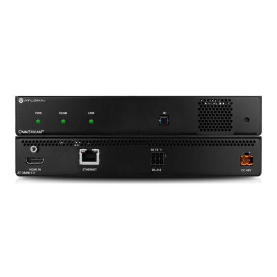
Page 10: Panel Description
Panel Description AT-OMNI-111 HDMI LINK TREAM HDMI LINK Front TREAM RX TX RX TX DC 48V HDMI IN ETHERNET RS-232 AT-OMNI-111 DC 48V HDMI IN ETHERNET RS-232 AT-OMNI-111 Rear HDMI This LED indicator glows bright green when the Connect an HDMI cable from this port to an HD unit is powered. -
Page 11: At-Omni-112
Panel Description AT-OMNI-112 DISPLAY INPUT HDMI LINK VOLUME DISPLAY INPUT TREAM HDMI LINK Front VOLUME TREAM RX TX RX TX HDMI IN ETHERNET RS-232 DC 48V AT-OMNI-112 HDMI IN ETHERNET RS-232 DC 48V AT-OMNI-112 Rear broadcast network notification to any devices This LED indicator glows bright green when the that may be listening (AMS). -
Page 12: Installation
Installation External Power (Optional) OmniStream encoders are powered by PoE (Power over Ethernet), when connected to a PoE-capable switch. If a PoE-switch is not used, then the optional 48 V power supply (Atlona part no. AT-PS-48083-C) can be purchased, separately. Insert the positive and negative leads, from the power supply, into the terminals of the 2-pin captive screw connector block, as shown. -
Page 13: Ir Connections
Installation IR Connections The same port that provides RS-232 connections also supports bidirectional IR pass-through, allowing a device to be controlled from either the headend or the decoder endpoint. This step is optional. IR control is only supported on RS-232 2 port (bottom set of connectors). Refer to IR Control (page 33) for configuration details. -
Page 14: Connection Instructions
Installation Connection Instructions 1. Connect an Ethernet cable from the ETHERNET port on the encoder to a PoE-capable switch on the Local Area Network (LAN). If using the dual-channel encoder, connect a separate Ethernet cables to ETHERNET 1 and ETHERNET 2 ports. IMPORTANT: If a PoE-capable switch is not available, then the 48V DC power supply (sold separately) must be connected to the encoder. -
Page 15: Connection Diagram
Installation Connection Diagram Blu-ray Player Automation Control System CT OR RE SE 48 V IN PU DI SP M NI AT-OMNI-112 Projector AT-OMNI-122 M NI AT-OMNI-111 / AT-OMNI-112... -
Page 16: Configuration
Configuration Accessing Encoders in AMS It is recommended that the Atlona Management System (AMS) be used to configure and control OmniStream devices. AMS uses multicast Domain Name Server (mDNS) to automatically discover each encoder on the network. AMS is free and can be downloaded from https://www.atlona.com/ams. By default, the encoders are set to DHCP mode, allowing a DHCP server (if present) to assign the encoder an IP address. - Page 17 Configuration 6. Click Devices from the fly-out menu. 7. Click the Unassigned option. 8. Click the left and right arrows, at the bottom of the Unassigned list, to scroll through all available devices. Arrow buttons AT-OMNI-111 / AT-OMNI-112...
- Page 18 Configuration All available encoders will be displayed under the Unassigned category. When an encoder is unassigned, it means that it has not been assigned to a site, building, and/or room. Refer to the AMS User Manual for more information on these topics. If a DHCP server is not found within 60 seconds, the encoder will be placed in Auto IP mode and assigned an IP address within the range of 169.254.xxx.xxx.
- Page 19 Configuration 11. Click SESSION in the top menu bar. 12. Locate the Video section. 13. Delete the value in the Destination Multicast / Unicast Address field. Destination Multicast/Unicast Address field 14. Locate the Audio section and delete the value in the Destination Multicast / Unicast Address field. Destination Multicast/Unicast Address field SAVE button 15.
-
Page 20: Configuring A Static Ip Address
Configuration Configuring a Static IP Address The following section is only required to when setting an encoder to a static IP address. If a DHCP server is not found within 60 seconds, encoders are automatically placed in Auto IP mode and will be assigned an IP address within the range 169.254.xxx.xxx. -
Page 21: Input Selection
Configuration Input Selection Once the OmniStream encoder is configured, and can be located on the network, the encoder will need to be instructed on how to handle source devices and to which stream each source is assigned. Input Selection 1. Under AMS, click INPUT in the menu bar. 2. -
Page 22: Verifying The Input
Configuration Dual-channel encoder only: 7. Repeat the above steps for the Encoder 2 section (dual-channel OmniStream only). If a secondary HDMI source is not connected to the encoder, then these fields may be left at their current settings. Dual-channel / single-channel encoder: 8. -
Page 23: Session Configuration
Configuration Session Configuration Once the inputs have been assigned to the desired source, the next step is to configure each session. A session is a class-D multicast IP address that is assigned to an AV stream. If each stream is configured for bit rates less than 450 Mbps (only recommended for 1080p and lower resolutions), a single Ethernet cable can transport two sessions. -
Page 24: Basic Operation
Basic Operation LED Indicators The following table provides a listing of front-panel LED indicators and their status: Description • If using a PoE switch, make sure that the port on the switch that is connected to the encoder, has PoE enabled. When the encoder is powered using PoE, the PWR indicator will be green. -
Page 25: Rebooting Omnistream
Basic Operation Rebooting OmniStream To reboot the OmniStream encoder, press and release the recessed button, on the far-right side of the unit, using a small, pointed object. Rebooting the encoder does not reset the encoder to factory-default settings. DISPLAY INPUT HDMI LINK VOLUME... -
Page 26: Adjusting Volume
Basic Operation Adjusting Volume Refer to the OmniStream Single-Channel / Dual Channel A/V Decoder User Manual, for configuration information. Press and release the (up) or (down) VOLUME buttons to increase or decrease the audio volume, respectively, in 1 dB increments. The volume command is sent over IP. After the decoder receives the command, it is executed and transmitted to the display using RS-232 and/or CEC. -
Page 27: Id Button
Basic Operation ID Button The ID button, on both the AT-OMNI-111 and AT-OMNI-112, serves two functions: 1. Sends a broadcast message over the network to any devices that may be listening. 2. Resets the encoder to factory-default settings. DISPLAY INPUT HDMI LINK VOLUME... -
Page 28: Input Switching Configuration
Basic Operation Input Switching Configuration IMPORTANT: This feature is not available on the single-channel OmniStream encoder (AT- OMNI-111). The INPUT button on the front panel can be configured to switch between both HDMI inputs. This is useful in meeting room applications, allowing switching between two sources. Note that when configuring input switching, one of the encoder sessions will be lost, causing dual-channel encoders to function as single-channel encoders. -
Page 29: Unicast Mode
Basic Operation Unicast Mode The term unicast is used to describe a configuration where information is sent from an encoder to a single decoder. Although it is common to have multiple encoder and decoder units within a system, it may also be desirable to restrict a single encoder to communicate with one decoder. - Page 30 Basic Operation 5. Go to the decoder AMS interface. Refer to the OmniStream Single-Channel / Dual Channel A/V Decoder User Manual, if necessary. 6. Click IP INPUT from the menu. 7. Remove the IP address from the Multicast Address field. 8.
-
Page 31: Multicast Mode
Basic Operation Multicast Mode The term multicast is used to describe a configuration where information is sent from one or more points to a set of other points. For example, a single encoder can transmit data to multiple decoders. In addition, if multiple encoders are used, each encoder can stream data to any decoder that is not already receiving data from an encoder. - Page 32 Basic Operation AT-OMNI-111 / AT-OMNI-112...
-
Page 33: Ir Control
IR Control Controlling the Display using the Display’s IR Remote The same port that provides RS-232 connections also supports bidirectional IR pass-through, allowing a device to be controlled from either the headend or the decoder endpoint. This step is optional. IR control is only supported on RS-232 2 port (bottom set of connectors). -
Page 34: Required Equipment
IR Control Required Equipment Atlona has tested and verified the following components for this application. However, other components may also be used. Note that IR control is only supported on RS-232 2 port (bottom set of connectors) of the OmniStream encoder and decoder. -
Page 35: Connecting The Ir Emitter To The Decoder
IR Control 2. Connect the IR IN and GND leads, from the 789-44 4-Source Connecting Block, to the to the RX and pins, respectively, of the RS-232 2 port (bottom port) of the encoder, as shown. NOTE: The IR IN, GND, and +12 VDC wires, from Step 1, have been removed from the illustration below, for purposes of clarity. -
Page 36: Identifying The Encoder Using Ams
IR Control Identifying the Encoder using AMS 1. Launch a web browser and enter the IP address of AMS in the address bar. 2. Enter the required login credentials. The default login is: Username: admin Password: Atlona 3. Click the Login button. 4. -
Page 37: Configuring The Encoder Serial Port
IR Control Configuring the Encoder Serial Port The first step will be to configure the RS-232 port on the encoder to use IR. Only the RS-232 2 port supports both RS-232 and IR. Therefore, this port must be used for IR. RS-232 port configuration is managed under the Serial page of the encoder web interface. -
Page 38: Configuring The Encoder Session
IR Control Configuring the Encoder Session The next step is to assign the IR control for Serial Port 2 to the desired Session. 1. Click SESSION in the top menu bar. 2. Locate the Session 1 window group. NOTE: Session 2 can also be used with IR. However, in this example, Session 1 will be configured. AT-OMNI-111 / AT-OMNI-112... - Page 39 IR Control 3. Scroll down and locate the AUX section. 4. Click the Source drop-down list and select serial_port2. 5. Enable the auxiliary (AUX) channel by clicking the Enable toggle switch. When the auxiliary channel is enabled, this toggle switch will be orange. 6.
-
Page 40: Configuring The Decoder Serial Port
IR Control Configuring the Decoder Serial Port 1. Select the desired decoder within the AMS Device List window and make note of the decoder IP address. 2. Enter the required login credentials. The default login is: Username: admin Password: Atlona 3. - Page 41 IR Control 8. Click Serial in the top menu bar. 9. Locate the Serial port configuration window group. The Name field, within this group, should read serial_ port2. Click the Modes drop-down list and select Infrared. 10. Click the SAVE button to commit changes. SAVE button 11.
- Page 42 IR Control 15. Click the SAVE button to commit changes. AT-OMNI-111 / AT-OMNI-112...
-
Page 43: Testing Ir Functionality
IR Control Testing IR Functionality 1. Point IR remote to at the IR Receiver, as shown in the diagram below. 2. The IR remote will now sent IR data to the decoder where it will be relayed to the display device. IMPORTANT: The IR lens of the emitter must be within 1 inch (2.54 centimeters) of the IR window on the display device. -
Page 44: Controlling The Display Using A Control System
IR Control Controlling the Display using a Control System The following steps are similar to Controlling the Display using the Display’s IR Remote (page 33), except that the control system wiring should be used, instead of an IR receiver, as shown below. Blu-ray Player IN PU ste m... -
Page 45: Using The Virtual Matrix
IR Control Using the Virtual Matrix 1. Login to AMS. Refer to Accessing Encoders in AMS (page 16) if necessary. 2. Click the icon, in the upper-left corner of the AMS Dashboard. 3. Click on Virtual Matrix. 4. The OmniStream Virtual Matrix page will be displayed. AT-OMNI-111 / AT-OMNI-112... - Page 46 IR Control 5. Click on the View drop-down list and select Control. 6. The Control screen will be displayed. In the Control screen, HDMI ports are replaced with control ports: Port 1 In / Port 1 In for encoders and Port 1 Out / Port 2 Out for decoders. 7.
- Page 47 IR Control 8. The Crosspoint Options dialog will be displayed. 9. Click the Serial Port 2 drop-down list and select IR Passthrough. NOTE: Only Serial Port 2 supports IR pass-through. The IR emitter or IR receiver must be connected to this port. Refer to RS-232 Connections (page 12) for wiring information.
-
Page 48: Advanced Operation
Advanced Operation Control Using RS-232 RS-232 data can be sent over IP using one of three methods: RS-232 pass-through, RS-232 triggering, and TCP proxy. Refer to the OmniStream Single-Channel / Dual-Channel Networked AV Encoder User Manual for information on configuring RS-232 triggering. NOTE: When configuring RS-232, always make sure to configure the correct baud rate, data bits, parity bit, stop bits, and flow control settings, as required by the connected device. -
Page 49: Using The Virtual Matrix
Advanced Operation Using the Virtual Matrix 1. Login to AMS. Refer to Accessing Encoders in AMS (page 16) if necessary. 2. Click the icon, in the upper-left corner of the AMS Dashboard. 3. Click on Virtual Matrix. 4. The OmniStream Virtual Matrix page will be displayed. AT-OMNI-111 / AT-OMNI-112... - Page 50 Advanced Operation 5. Click on the View drop-down list and select Control. 6. The Control screen will be displayed. In the Control screen, HDMI ports are replaced with control ports: Port 1 In / Port 1 In for encoders and Port 1 Out / Port 2 Out for decoders. 7.
- Page 51 Advanced Operation 6. The Crosspoint Options dialog will be displayed. 7. Click the ADVANCED button, near the bottom of the dialog. This will enable additional options in the Serial Port drop-down lists. In the BASIC mode, only RS232 Passthrough is available from drop-down list. When the ADVANCED option is enabled, the following modes will be available.
- Page 52 Advanced Operation RS232 Passthrough This is the most basic option: the control system (DTE device) sends RS-232 commands from the encoder, downstream, to the decoder. The RS-232 commands are then received by a display (DCE device) or other sink device. 1.
- Page 53 Advanced Operation Serial over IP Proxy (TCP Proxy) This method is used to send IP commands directly to the decoder, which are then output over RS-232 to the display (sink) device. 1. Select Serial over IP Proxy from the Serial Mode drop-down list. If it is not listed, make sure that the Advanced button is clicked, at the bottom of the dialog.
-
Page 54: 802.1X Authentication
Advanced Operation 802.1X Authentication 802.1X is a server-based port authentication which restricts unauthorized (rogue) clients from connecting to a Local Area Network through a public port. In its simplest form, 802.1X usually involves three parties: supplicant (client device), authenticator (Ethernet switch or WAP), and an authentication server. Before the device is permitted on the network, port communication is restricted to Extensible Authentication Protocol over LAN (EAPOL) traffic. - Page 55 Advanced Operation 1. Login to AMS. Refer to Accessing Encoders in AMS (page 16), if necessary. 2. Click Devices > All and select the desired encoder from the Device List. 3. Click NETWORK in the menu bar. NOTE: If using dual-channel encoders, both Network 1 (eth1) and Network 2 (eth2) will need to be set up, depending upon the system requirements.
- Page 56 Advanced Operation 7. Click SAVE to commit changes. 8. Refer to the table below for a list of available authentication methods. An orange dot indicates that this field will be displayed as part of the method. Authentication Method Identity Password CA Certificate CA Certificate Client Private Certificate...
-
Page 57: Aes67 Audio
Advanced Operation AES67 Audio AES67 audio is a standard for high-performance audio streaming over IP, providing several features such as synchronization, media clock identification, and connection management. AES67 does not support compressed audio formats, such as Dolby® Digital, and others. Source audio must be transmitted as LPCM 2.0 or 5.1. 1. -
Page 58: Edid Management
Advanced Operation EDID Management OmniStream encoders provide EDID management for each input. The encoder can be assigned one of several included EDID presets or can be assigned a custom EDID. Raw EDID data can be copied from displays or other sink devices, that are connected to OmniStream decoders. - Page 59 Advanced Operation 6. Enter the EDID data in the Raw EDID field. EDID data can be copy and pasted from an EDID editor and must be in hexadecimal format. Commas or spaces can be included as delimiters to separate each hexadecimal value. 7.
-
Page 60: Copying An Edid From The Display
Advanced Operation Video mode only EDID Dolby Dolby DTS-HD Dolby LPCM LPCM Digital* MA † True HD* Default -Video Mode Default - Video Mode (No HDR) 4K60 MCH 4K60 PCM-MCH 460 LPCM 2CH 720P DD 720P 2CH * Dolby Atmos® is carried with either Dolby Digital Plus or Dolby True HD audio streams. †... - Page 61 Advanced Operation 4. Locate the EDID section. This is the EDID of the display which is connected to the decoder. Click and select the data in this field, then press [CTRL]+[C] to copy the data. Display’s EDID 5. Select the desired encoder, within AMS. 6.
- Page 62 Advanced Operation 9. Enter the name of the EDID in the EDID Name field. Spaces and special character are valid entries. Use a descriptive name for this field. 10. Paste the EDID data into the Raw EDID field by pressing [CTRL]+[P]. 11.
-
Page 63: Encoder Grouping
Advanced Operation Encoder Grouping Grouping encoders allows a group of encoders to feed a single decoder, simultaneously. The stream will be displayed by the decoder using either manual or automatic input-selection, based on the presence of a source signal. 1. Login to AMS. Refer to Accessing Encoders in AMS (page 16), if necessary. - Page 64 Advanced Operation 9. Click the Enable Encoder Group toggle switch to enable encoder grouping. When enabled, this toggle switch will be green. 10. Click the Trigger drop-down list and select the desired trigger mode. Enable Encoder Group Mode Description manual Use this setting to manually enable the input.
-
Page 65: Daisy-Chaining Encoders
Advanced Operation Daisy-Chaining Encoders Encoders can be daisy-chained to one another. This is particularly useful when only a single distribution point and one display exists in a room. Daisy-chaining transforms multiple encoders into a single multiple-input encoder with a single multicast IP address. In the diagram below, three dual-channel OmniStream encoders are connected to a switch. - Page 66 Advanced Operation Figure 1. Daisy-chained encoders with single decoder and display (sink). Display PoE (optional) Network Switch Legend AT-OMNI-122 HDMI cable M NI Ethernet cable A/V signals IN PU DI SP M NI IN PU DI SP M NI IN PU DI SP M NI Laptop...
-
Page 67: Scrambling
Advanced Operation Scrambling OmniStream supports 128-bit Advanced Encryption Standard (AES) scrambling for both audio and video streams. Scrambling can be enabled or disabled through AMS, and can be individually applied to video, audio, or both. Scrambling can be enabled either before or after the decoding process is started. Data streams cannot be scrambled. -
Page 68: Using The Virtual Matrix
Advanced Operation Using the Virtual Matrix 1. Access the Virtual Matrix. Refer to The Virtual Matrix (page 92) for more information. 2. Locate the desired encoder or decoder. Scrambling is managed on the encoder; descrambling is managed on the decoder. 3. -
Page 69: Setting The Video Mode
Advanced Operation Setting the Video Mode OmniStream offers two video modes: Video and PC application. These two modes will optimize the video, based on the type of information that is being displayed. Use the Video mode when display motion graphics/video. Set this mode to PC application when viewing static images, such as spreadsheets or similar content. -
Page 70: Slate / Logo Insertion
Advanced Operation Slate / Logo Insertion Slate / logo insertion is managed from within AMS. The difference between a “slate” and “logo” is in the size of the image and how it is used: Logos are classified as smaller, low-resolution images that can be positioned at specified locations on the screen. - Page 71 Advanced Operation Image window group 8. Perform one of the following: • If the selected image will be used as a logo, then proceed with Steps 9 through 13. • If the image will be used as a slate, skip to Step 14. 9.
- Page 72 Advanced Operation 10. Click the Aspect Ratio drop-down list to set the aspect ratio of the image. Selecting Keep will maintain the aspect ratio. Select Stretch to scale the image to fill the screen. 11. Enter the location of the on-screen image, in pixel values, by entering the desired values in the Horizontal and Vertical fields.
-
Page 73: Deleting Slates / Logos
Advanced Operation Deleting Slates / Logos Follow the instructions below to remove a logo/slate image. 1. Click OTHER in the menu bar. 2. Click the DELETE button in the desired image window group. When the DELETE button is clicked, the window group and the associated image will be deleted from the encoder. -
Page 74: Text Insertion
Advanced Operation Text Insertion 1. Login to AMS. Refer to Accessing Encoders in AMS (page 16), if necessary. 2. Click OTHER in the menu bar. 3. Click Text in the side menu bar, in the upper-left corner of the AMS screen. 4. -
Page 75: The Ams Interface
The AMS Interface Device Info page The Device Info page provides general information about the encoder. Alias Enter a name for the unit in this field. This is optional. Model The model number of the unit. Model Description AT-OMNI-111 Single-channel encoder AT-OMNI-112 Dual-channel encoder IP Address... - Page 76 The AMS Interface Location Provides the option of assigning descriptor for the location of the unit. Uptime Time elapsed since the last reboot operation. Hostname The hostname of this unit. This can be changed if desired. By default, the host name is automatically created using the model of the unit and adding the last five digits of the unit serial number.
- Page 77 The AMS Interface NTP Server Specify the desired NTP server in this field. This provides timestamps for any logs and alarms. Buttons Disabling this feature will lock the ID button on the front panel. This feature is enabled by default. LEDs Disabling this feature will turn off all LED indicators on the front panel.
-
Page 78: Input Page
The AMS Interface Input page The Input page provides signal information for each channel (input). If using the single-channel encoder, only a single (input) channel will be displayed. Input The selected input. This value can be HDMI Input 1, Video Generator 1, or None. Bit Rate The current video bit rate. - Page 79 The AMS Interface EDID Click the drop-down list to select the desired EDID. Refer to the table elow for a list of available EDID selections. EDID Description Default Default OmniStream EDID ATL 1080P 2CH 1920x1080p60 with two-channel PCM audio ATL 1080P DD 1920x1080p60 with Dolby Digital audio ATL 1080P DVI 1920x1080p60 with video formatted as DVI...
- Page 80 The AMS Interface Advanced Settings Click the SHOW ADVANCED button to view the following options. Slate Mode Click this drop-down list to enable slate mode or select the desired slate to be used. Refer to Slate / Logo Insertion (page 70) for more information.
-
Page 81: Serial Page
The AMS Interface Serial page The Serial page provides serial port configuration when using control signals. Supported Modes Lists the supported protocols for the serial port. Mode Click this drop-down list to select the desired serial mode. Baud Rate Click this drop-down list to select the desired baud rate: 9600, 19200, 38400, 57600, or 115200. Data Bit Click this drop-down list to select the number of data bits: 6, 7, or 8. - Page 82 The AMS Interface Advanced Settings Click the SHOW ADVANCED button to view the following options. Command Each of these Command window groups are used to enter the command string for the desired operation: Display Off, Display On, Volume Down, and Volume Up. Interpret on Click this drop-down list to select where the command will be interpreted.
-
Page 83: Session Page
The AMS Interface Session page The Session page provides the ability to configure all session parameters. Up to four sessions are supported on dual-channel encoders. Single-channel encoders are limited to a maximum of two sessions. Interface Click this drop-down list to select the desired interface. Interface Description eth1... - Page 84 The AMS Interface Encoder Click this drop-down list to select the desired HDMI input. Enable Video Click the toggle switch to enable or disable the video stream. When enabled, the toggle switch will be green. By default, video streaming is enabled. Disabling the video stream can be used to “mask” the video on the decoder endpoints.
- Page 85 The AMS Interface Advanced Settings Click the SHOW ADVANCED button to view the following options. DSCP, FEC Enable, FEC Rows, and FEC Columns apply to both Video and Audio sections. DSCP Select the Differentiated Services Code Point (DSCP) type from the DSCP drop-down list. This value will be used to determine the Quality of Service (QoS) on a network.
-
Page 86: Network Page
The AMS Interface Network page The Network page provides the ability to enable or disable DHCP mode for each video channel. When DHCP mode is disabled, the IP address, subnet mask, and gateway must be provided. If using the dual-channel version, then the information on both Channel 1 and Channel 2 are provided. - Page 87 The AMS Interface Advanced Settings Click the SHOW ADVANCED button to view the following options. Link Speed Displays the port speed in Mbps. MAC Address The MAC address of the Ethernet channel. Telnet Authentication Click this toggle switch to enable or disable Telnet authentication. If enabled, then the toggle switch will be green. Once enbled, connecting to the encoder using Telnet will require login credentials.
-
Page 88: Other Page
The AMS Interface Other page The Other page provides logo/slate, text, and PTP management. Click the menu in the upper-left corner of the AMS screen to switch between Logo, Text, and PTP screens. Logo The Logo page provides the ability to upload a custom logo. This logo will be displayed when no video signal is detected. -
Page 89: Text
The AMS Interface Vertical Enter the vertical position of the logo on the screen. Height Enter the horizontal resolution of the logo, in pixels. Width Enter the vertical resolution of the logo, in pixels. IMPORTANT: Maximum logo resolution (both height and width) is 1/4 of the video resolution. Text The Text page provides the ability to display scrolling or stationary text superimposed on the source image. -
Page 90: Ptp
The AMS Interface Horizontal (%), Vertical (%) Specify the location of the text in the Horizontal (%) and Vertical (%) fields. Each of these values is based on the horizontal and vertical resolution of the screen. Width (%), Height (%) Specify the size of the text in the Width (%) and Height (%) fields. - Page 91 The AMS Interface Domain Number Enter the domain number in this field. Valid entries are 0 through 127. Priority 1 Enter the priority number in this field. Priority 2 Enter the priority number in this field. Is GM Present This indicator displays the existence of a grandmaster clock for the specified PTP domain number. If the indicator is green, then the grandmaster clock exists on this interface.
-
Page 92: The Virtual Matrix
The AMS Interface The Virtual Matrix 1. Login to AMS. Refer to Accessing Encoders in AMS (page 16), if necessary. 2. Click the icon, in the upper-left corner of the AMS Dashboard. 3. Click Virtual Matrix. 4. The OmniStream Virtual Matrix page will be displayed. AT-OMNI-111 / AT-OMNI-112... -
Page 93: Layout And Operation
The AMS Interface Layout and Operation The illustration below, shows a multiple OmniStream units (encoders and decoders). The Virtual Matrix is organized into rows and columns. The blue circle with the checkmark indicates that these two OmniStream units are connected to one another. The second column identifies a dual-channel decoder (AT-OMNI-122). - Page 94 The AMS Interface When these icons are clicked, the associated icons will be displayed in the rows and columns of the Virtual Matrix. Symbol Description Video only Audio only Data only Connected; not all signals are active Connected; all streams are being used Video stream Audio stream Data stream...
-
Page 95: Appendix
Appendix Updating the Firmware IMPORTANT: • If updating from version 1.0.x, OmniStream units must first be updated to version 1.1. Note that this does not apply to OmniStream R-Type units. If running version 1.0.x, contact an Atlona Technical Support Engineer before updating the firmware. •... - Page 96 Appendix 5. After the UPDATE FIRMWARE button is clicked, the Upgrade Firmware Started message box will be displayed. 6. Click the orange up-arrow icon, in the upper-right corner of the screen, as shown below. If this icon is orange, it indicates that a firmware update is in progress. The progress bar for the update process will be displayed.
-
Page 97: Fec Details
Appendix FEC Details Matrix Size, Overhead, and Latency • FEC can only work if a single packet from each row/column is missing. Multiple packets missing from each row/ column will cause FEC to fail. • Due to the above, a smaller matrix is more robust, as there is a better chance of errors not occurring in the same row/column. -
Page 98: Fec, Latency, And Lip Sync
Appendix FEC, Latency, and Lip Sync • In order for FEC to work, the matrix must be filled in order to calculate the FEC packets. This introduces some additional latency. Due to high bitrates, this is not noticeable for video, but can be very significant for audio. Therefore, Atlona recommends either leaving FEC disabled for audio or using a very small matrix. -
Page 99: Mounting Instructions
Appendix Mounting Instructions OmniStream encoders includes two mounting brackets 6. Mount the unit using the oval-shaped holes, on each and four mounting screws, which can be used to attach rack ear. If using a drywall surface, a #6 drywall the unit to any flat surface. screw is recommended. -
Page 100: Rack Tray For Omnistream
Appendix Rack Tray for OmniStream OmniStream encoders can also be mounted in the OmniStream rack tray (AT-OMNI-1XX-RACK-1RU). The rack tray is sold separately and provides easy mounting and organization of up to two OmniStream encoders/decoders in a convenient 1U rack tray. The OmniStream rack tray can be purchased directly from Atlona. 1. -
Page 101: Specifications
Appendix Specifications Single-Channel Encoder Video HDMI Specification HDMI 2.0, HDCP 1.4 / 2.2 UHD/HD 4096×2160(DCI)@60/30/24 Hz, 3840×2160(UHD)@60 /50/24/25/30 Hz, 1080p@23.98/24/25/29.97/30/ 50/59.94/60 Hz, 1080i @25/29.97/30 Hz, 720p@30/50/59.94/60 Hz VESA 1920x1200, 1680x1050, 1600x1200, 1600x900, 1440x900, 1400x1050, 1366x768, 1360x768, 1280x1024, 1280x800, 1280x768, 1152x768, 1024x768 Color Space YUV, RGB Encoding... - Page 102 Appendix Connectors HDMI 1 - Type A, 19-pin, female, locking ETHERNET 1 - RJ45, 10/100/1000 Mbps RS-232 / IR 1 - Euroblock, 6-pin (2 ports); RS-232 on port 1, IR on port 2 Power 1 - Euroblock, 2-pin Indicators and Controls 1 - LED, tricolor (red, amber, green) HDMI 1 - LED, bicolor (red, green)
-
Page 103: Dual-Channel Encoder
Appendix Dual-Channel Encoder Video HDMI Specification HDMI 2.0, HDCP 1.4 / 2.2 UHD/HD 4096×2160 (DCI) @60/30/24 Hz, 3840×2160(UHD)@60 /50/24/25/30 Hz, 1080p@23.98/24/25/29.97/30 /50/59.94/60 Hz, 1080i @25/29.97/30 Hz, 720p@30/50/59.94/60 Hz VESA 1920x1200, 1680x1050, 1600x1200, 1600x900, 1440x900, 1400x1050, 1366x768, 1360x768, 1280x1024, 1280x800, 1280x768, 1152x768, 1024x768 Color Space YUV, RGB Encoding... - Page 104 Appendix Connectors HDMI 2 - Type A, 19-pin, female, locking ETHERNET 2 - RJ45, 10/100/1000 Mbps RS-232 / IR 1 - Euroblock, 6-pin (2 ports); RS-232 on port 1 and 2, IR on port 1 and 2 Power 1 - Euroblock, 2-pin Indicators and controls 1 - LED, tricolor (red, amber, green) HDMI...
- Page 105 Toll free US International atlona.com 877.536.3976 41.43.508.4321 • • © 2019 Atlona Inc. All rights reserved. “Atlona” and the Atlona logo are registered trademarks of Atlona Inc. All other brand names and trademarks or registered trademarks are the property of their respective owners. Pricing, specifications and availability subject to change without notice.
Need help?
Do you have a question about the ATLONA OmniStream AT-OMNI-111 and is the answer not in the manual?
Questions and answers