Banner SureCross FlexPower DX80 Series Manual
Hide thumbs
Also See for SureCross FlexPower DX80 Series:
- Network manual (110 pages) ,
- Product manual (109 pages) ,
- Reference manual (96 pages)
Advertisement
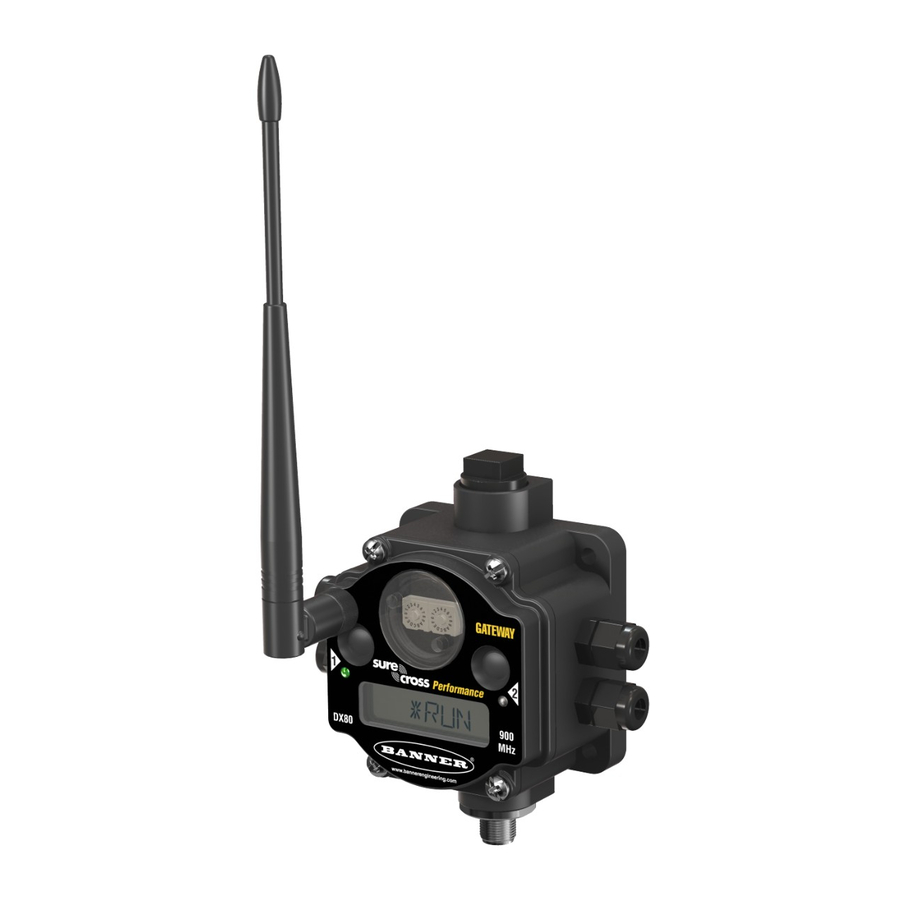
SureCross DX80 FlexPower Node
Configurable Node with switched power outputs, discrete inputs, discrete NMOS outputs, and analog inputs
IP67 Base
2.4 GHz
IP20 Base
900 MHz
For additional information, updated
documentation, and accessories,
refer to Banner Engineering's web-
site,
www.bannerengineering.com/
surecross.
Models (0-20 mA Analog
Frequency
Inputs)
900 MHz ISM
DX80N9X2S2N2M2
Band
2.4 GHz ISM
DX80N2X2S2N2M2
Band
900 MHz ISM
DX80N9X2S2N2M2C
Band
2.4 GHz ISM
DX80N2X2S2N2M2C
Band
Models (0-10V Analog
Frequency
Inputs)
900 MHz ISM
DX80N9X2S2N2V2
Band
2.4 GHz ISM
DX80N2X2S2N2V2
Band
900 MHz ISM
DX80N9X2S2N2V2C
Band
2.4 GHz ISM
DX80N2X2S2N2V2C
Band
Internal antenna models are also available. For more information, contact your local Banner Engineering Corp. representative.
P/N 131296 Rev. L
The SureCross® wireless system is a radio frequency network with integrated I/O that can oper-
ate in most environments and eliminate the need for wiring runs. Wireless networks are formed
around a Gateway, which acts as the wireless network master device, and one or more Nodes.
• Wireless industrial I/O device with two discrete inputs, two discrete (NMOS sinking) outputs
when configured for discrete mode; two discrete inputs, two discrete outputs, and two analog
inputs when configured for analog mode
• FlexPower® power options allows for +10 to 30V dc, solar, and battery power sources for low
power applications.
• DIP switches for user configuration
• Multiple switched power outputs can be switch configured to provide sensor actuation voltage
from the battery supply
• Frequency Hopping Spread Spectrum (FHSS) technology and Time Division Multiple Access
(TDMA) control architecture ensure reliable data delivery within the unlicensed Industrial, Sci-
entific, and Medical (ISM) band
• Transceivers provide bidirectional communication between the Gateway and Node, including
fully acknowledged data transmission
• Lost RF links are detected and relevant outputs set to user-defined conditions
• The DX80...C models are certified for use in Class I, Division 2, Group A, B, C, D; Zone 2
(Category 3G) Hazardous Locations when properly installed in accordance with the National
Electrical Code, the Canadian Electrical Code, or applicable local codes/regulations (see
Specifications)
Environmental Rat-
ing
IP67, NEMA 6
Discrete Mode
Inputs: Two selectable discrete
Outputs: Two NMOS discrete
Switch Power: Two, Configurable
IP20, NEMA 1
Environmental Rat-
ing
IP67, NEMA 6
Discrete Mode
Inputs: Two selectable discrete
Outputs: Two NMOS discrete
Switch Power: Two, Configurable
IP20, NEMA 1
5/21/2013
Inputs and Outputs
Analog Mode
Inputs: Two selectable discrete, two 0
to 20 mA analog
Outputs: Two NMOS discrete
Switch Power: One, Configurable
Inputs and Outputs
Analog Mode
Inputs: Two selectable discrete, two 0
to 10V analog
Outputs: Two NMOS discrete
Switch Power: One, Configurable
0 131296
6
Advertisement
Table of Contents

Related Manuals for Banner SureCross FlexPower DX80 Series


Summary of Contents for Banner SureCross FlexPower DX80 Series
- Page 1 Switch Power: Two, Configurable Band Switch Power: One, Configurable IP20, NEMA 1 2.4 GHz ISM DX80N2X2S2N2V2C Band Internal antenna models are also available. For more information, contact your local Banner Engineering Corp. representative. P/N 131296 Rev. L 5/21/2013 0 131296...
-
Page 2: Setting Up Your Wireless Network
The UCT requires a special USB to RS-485 (model number BWA-UCT-900 for 1 Watt radios, BWA-HW-006 can be used for all other radios) converter cable to pass infor- mation between your computer and the Gateway. Download the most recent revi- sions of the UCT software from Banner Engineering's website: http://www.banneren- gineering.com/wireless. - Page 3 SureCross DX80 FlexPower Node After making the necessary changes to the DIP switches, place the black cover plate back into position and gently push into place. Plug the ribbon cable in after verifying that the blocked hole lines up with the missing pin.
- Page 4 SureCross DX80 FlexPower Node Analog Configuration, Switch 2 OFF DIP Switches Descriptions Sample/Report Rate 64 seconds Sample/Report Rate 5 minutes Modbus or UCT configured (overrides DIP switches) Sample/Report Rate 15 minutes Analog IN 2 (not available in integrated battery model), Discrete 1, and Discrete 2 are not powered from switched power terminals. In this configuration, SP2 is disabled.
- Page 5 SureCross DX80 FlexPower Node Wiring Your SureCross® Device Use the following wiring diagrams to first wire the sensors and then apply power to the SureCross devices. 5-pin Euro-Style Wiring (Nodes) Wiring the 5-pin Euro-style connector depends on the model and power requirements of the device. Connecting dc power to the commu- nication pins will cause permanent damage.
- Page 6 SureCross DX80 FlexPower Node IP67 Base IP20 Base SPx. Switch Power. Provides variable power sources for external devices. (SP3 and SP4 are not used for the factory default config- uration of this model.) Wiring Diagrams for Discrete Inputs Connecting dc power to the communication pins will cause permanent damage. For the DX8x...C models, PWR in the wiring diagram refers to V+ on the wiring board and GND in the wiring diagram refers to V- on the wiring board.
- Page 7 SureCross DX80 FlexPower Node • To reduce power consumption and extend battery life, slower sample and reporting rates are used. Faster sample and report rates can be configured, but this will decrease the battery’s life. For details, refer to the included table of DIP switch configurable parame- ters.
-
Page 8: Specifications
SureCross DX80 FlexPower Node Modbus Holding Register I/O Type Units I/O Range Holding Register Repre- Terminal sentation Block La- bels Gate- Any Node Min. Max. Min. (Dec.) Max. (Dec.) 10 + (Node# × 16) Discrete OUT 2 15 + (Node# × 16) Control Message 16 + (Node# ×... - Page 9 SureCross DX80 FlexPower Node Inputs and Outputs Analog Inputs Switch Power Outputs Rating for 0 to 20 mA models: 24 mA Analog configuration: one Rating for 0 to 10V models: 10V Discrete configuration: two Impedance: 100 Ohms Host configuration: up to four Sample/Report Rates (Analog IN 1): DIP switch config- To verify the analog input's impedance, use an Ohm meter to urable (see tables)
-
Page 10: Banner Engineering Corp Limited Warranty
ER ARISING IN CONTRACT OR WARRANTY, STATUTE, TORT, STRICT LIABILITY, NEGLIGENCE, OR OTHERWISE. Banner Engineering Corp. reserves the right to change, modify or improve the design of the product without assuming any obligations or liabilities relating to any product previously manufactured by Banner Engineering Corp.
Need help?
Do you have a question about the SureCross FlexPower DX80 Series and is the answer not in the manual?
Questions and answers