
Related Manuals for Pepperl+Fuchs VBA-2E-KE5-IJL


Summary of Contents for Pepperl+Fuchs VBA-2E-KE5-IJL
- Page 1 FACTORY AUTOMATION MANUAL VBA-2E-KE5-IJL/UJL AS-Interface Analog Module Spec 2.1...
- Page 2 VBA-2E-KE5-IJL/UJL With regard to the supply of products, the current issue of the following document is ap- plicable: The General Terms of Delivery for Products and Services of the Electrical Indus- try, published by the Central Association of the Electrical Industry (Zentralverband Elektrotechnik und Elektroindustrie (ZVEI) e.V.) in its most recent version as well as the...
-
Page 3: Table Of Contents
VBA-2E-KE5-IJL/UJL Introduction................. 4 Content of this Document ..............4 Target Group, Personnel..............4 Symbols Used ..................5 Certificates and Approvals ............6 UL Information..................6 Product Description ..............7 Intended Use ..................7 Displays and Operating Elements ............7 Connections ..................8 Automatic Detection of the Sensor Type ........... -
Page 4: Introduction
VBA-2E-KE5-IJL/UJL Introduction Introduction Content of this Document This document contains information required to use the product in the relevant phases of the product life cycle. This may include information on the following: Product identification Delivery, transport, and storage Mounting and installation... -
Page 5: Symbols Used
VBA-2E-KE5-IJL/UJL Introduction Symbols Used This document contains symbols for the identification of warning messages and of informative messages. Warning Messages You will find warning messages, whenever dangers may arise from your actions. It is mandatory that you observe these warning messages for your personal safety and in order to avoid property damage. -
Page 6: Certificates And Approvals
VBA-2E-KE5-IJL/UJL Certificates and Approvals Certificates and Approvals UL Information Technical Data and Environmental Conditions This device is for indoor use only. This device may be operated in altitudes up to 2000 m. The ambient temperature range is from -25 °C to +70 °C. -
Page 7: Product Description
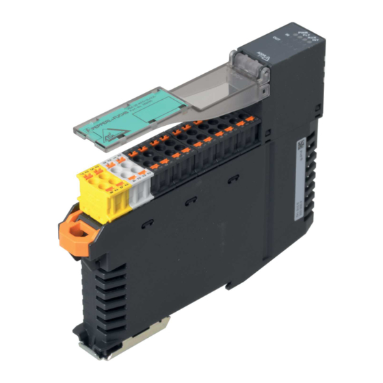
The sensors are supplied with power via the AS-Interface or auxiliary voltage. Displays and Operating Elements ADDR Figure 3.1 Displays and operating elements The VBA-2E-KE5-IJL/UJL analog module is equipped with the following indicators and operating elements: LED Indicators Description Function FAULT LED Fault indication;... -
Page 8: Connections
VBA-2E-KE5-IJL/UJL Product Description Switch Description Function INT/AUX switch Set to INT: inputs powered via the AS-Interface (max. 100 mA) Set to AUX: inputs powered via auxiliary voltage (max. 600 mA) Warning! Only use the switch when de-energized Only adjust the INT/AUX switch if the module is not supplied via the AS-Interface (INT) or the... -
Page 9: Automatic Detection Of The Sensor Type
VBA-2E-KE5-IJL/UJL Product Description Note! Switching Off the Second Channel Figure 3.3 Jumper for switching off input channel 2 Input channel 2 can be deactivated using a jumper between the GND and 1CH connections or using parameter P1. The jumper has priority. If no jumper is set and P1 = 1, then both channels are active. -
Page 10: Installation
Retain the original packaging in case the device must be stored or shipped again at a later date. Should you have any questions, please contact Pepperl+Fuchs. Mounting Mount the module by snapping it onto a 35 mm DIN rail in compliance with EN 50022. -
Page 11: Connecting The Sensors
VBA-2E-KE5-IJL/UJL Installation Connecting the Sensors You can connect 2-, 3-, and 4-wire sensors to the VBA-2E-KE5-IJL/UJL. For various connection options, see see Figure 4.2 on page 11 and see Figure 4.3 on page 11. The sensors are supplied via the AS-Interface or auxiliary voltage (AUX) -
Page 12: Commissioning
Pepperl+Fuchs, for example, or an AS-Interface master can be used to assign addresses. The VBA-2E-KE5-IJL/UJL is a standard slave as defined by specification 3.0 and requires a master that meets specification 2.1 or higher. You can assign addresses 1 to 31. The default address on delivery is 0. - Page 13 VBA-2E-KE5-IJL/UJL Commissioning Parameter P2: Peripheral Fault Default value P2=1, active Parameter P2 is used to switch notification of a peripheral fault in the event of a measuring overrange on or off (see chapter 7). If messages are activated, the PWR LED and FAULT LED flash in the event of a peripheral fault, and a message is sent to the master.
-
Page 14: Troubleshooting
II2) Wrong sensor type configured A different sensor type has already been configured through automatic detection of sensor type. To reset the sensor configuration, see see chapter 3.5 If none of these potential solutions correct the fault, please contact Pepperl+Fuchs. -
Page 15: Appendix
VBA-2E-KE5-IJL/UJL Appendix Appendix Analog Input Module Measuring Ranges Current Input Measuring Ranges The measuring range of the current input can be set via AS-Interface parameter P3: P3=1, nominal range 4 mA ... 20 mA P3=0, nominal range 0 mA ... 20 mA Current: 4 mA ... -
Page 16: Delay Times
VBA-2E-KE5-IJL/UJL Appendix Voltage Input Measurement Ranges Voltage: 0 V ... 10 V Input signal [V] Display on the master Input LED > 11.5 32767 Above threshold (peripheral fault) 10.001 ... 11.5 10001 ... 11500 Extended range 0 ... 10 0000 ... 10000 Nominal range <... - Page 17 VBA-2E-KE5-IJL/UJL Appendix Module Analog-to-digital conversion Analog-to-digital conversion Analog-to-digital conversion Channel 1 Channel 2 Channel 1 Transmission Transmission Transmission Transmission Channel 2 Channel 1 Channel 2 Channel 1 Conversion time ~ Transmission time x 3 Network Figure 7.1 Conversion time > Transmission time...
- Page 18 VBA-2E-KE5-IJL/UJL Appendix Transmission time The transmission time is based on the AS-Interface specification. The AS-Interface transmits data in 4-bit packets. At values greater than 4 bits, the quantity of data is divided into smaller values and then transmitted to a com unit over several cycles. If several channels are transmitted per slave, the number of cycles increases.
- Page 19 Twinsburg, Ohio 44087 · USA Tel. +1 330 4253555 E-mail: sales@us.pepperl-fuchs.com Asia Pacific Headquarters Pepperl+Fuchs Pte Ltd. Company Registration No. 199003130E Singapore 139942 Tel. +65 67799091 E-mail: sales@sg.pepperl-fuchs.com www.pepperl-fuchs.com Subject to modifications / DOCT-5664A Copyright PEPPERL+FUCHS • Printed in Germany 07/2018...
Need help?
Do you have a question about the VBA-2E-KE5-IJL and is the answer not in the manual?
Questions and answers