Table of Contents
Advertisement
Quick Links
Advertisement
Table of Contents

Related Manuals for Pepperl+Fuchs VLX-F231-B6


Summary of Contents for Pepperl+Fuchs VLX-F231-B6
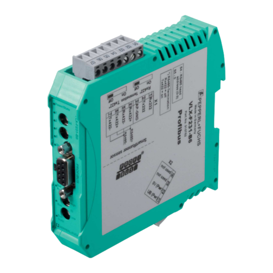
- Page 1 FACTORY AUTOMATION MANUAL VLX-F231-B6 VLX PROFIBUS DP Interface Module...
- Page 2 VLX-F231-B6 With regard to the supply of products, the current issue of the following document is ap- plicable: The General Terms of Delivery for Products and Services of the Electrical Indus- try, published by the Central Association of the Electrical Industry (Zentralverband Elektrotechnik und Elektroindustrie (ZVEI) e.V.) in its most recent version as well as the...
-
Page 3: Table Of Contents
VLX-F231-B6 Introduction................. 4 Content of this Document ..............4 Target Group, Personnel..............4 Symbols Used ..................4 Product Description ..............6 Use and Application ................6 Dimensions................... 6 Design of the Device................7 Installation................. 10 Mounting ..................... 10 Electrical Connection ................ 11 Dismounting .................. -
Page 4: Introduction
VLX-F231-B6 Introduction Introduction Content of this Document This document contains information required to use the product in the relevant phases of the product life cycle. This may include information on the following: Product identification Delivery, transport, and storage Mounting and installation... -
Page 5: Symbols Used
VLX-F231-B6 Introduction Symbols Used This document contains symbols for the identification of warning messages and of informative messages. Warning Messages You will find warning messages, whenever dangers may arise from your actions. It is mandatory that you observe these warning messages for your personal safety and in order to avoid property damage. -
Page 6: Product Description
PROFIBUS DP input card of the control panel. Data is transferred between the sensor or sensors and the VLX-F231-B6 interface module via the RS- 485 interface and from the VLX-F231-B6 interface module to the control panel via the PROFIBUS DP protocol. -
Page 7: Design Of The Device
VLX-F231-B6 Product Description Design of the Device Device Components Figure 2.2 Interface module overview RS-485 terminator sliding switch (behind the terminal block) X1: RS-485 interface Mounting bracket X2: Connection for power supply PROFIBUS communication interface Slide switch for PROFIBUS DP terminator... - Page 8 Figure 2.3 Front panel overview Sensor (VLX-F231-B6) Power The "Power" LED is green: The VLX-F231-B6 interface module is correctly connected to the power supply. State The "State" LED is green: Data is being exchanged with the sensor(s). The four "Error No/Select ID"...
- Page 9 VLX-F231-B6 Product Description LED ErrorNo/Select ID Error number Error description LED8 LED4 LED2 LED1 Reserved Hardware error EEPROM error Internal memory error Fieldbus hardware error or incorrect fieldbus ID Script error Reserved Sensor communication, RS send buffer overflow Sensor communication, RS receive...
-
Page 10: Installation
VLX-F231-B6 Installation Installation Mounting Mounting the Modules The module is fastened to a DIN mounting rail with a width of 35 mm using a snap-on fixing method. Figure 3.1 Mounting 1. Hook the module (1) onto the DIN mounting rail (2) from above and press it down until it snaps into place. -
Page 11: Electrical Connection
VLX-F231-B6 Installation Electrical Connection Danger! Device damage due to incorrect installation Incorrect installation of cables and connection lines can endanger the function and the electrical safety of the device. Observe the permissible core cross section of the conductor. If you are using stranded conductors, crimp the stranded conductors with wire end ferrules. - Page 12 VLX-F231-B6 Installation Connecting the Power Supply Connect the operating voltage (10 VDC...33 VDC) to Terminals 1 and 2 of the 4-pin plug X2 on the interface module. In addition, note the label on the module. The "Power" LED lights up green.
- Page 13 VLX-F231-B6 Installation Note! RS-485 Bus Termination If the interface module is operated as the first or last physical device in an RS-485 bus, there must be a bus termination on this module. To do this, set the "Rx 422 Termination" slide switch to "Off"...
-
Page 14: Dismounting
VLX-F231-B6 Installation Dismounting Dismounting the modules Use a suitable slot-head screwdriver for dismounting the module. 1. Disconnect all the supply and signal lines. Figure 3.3 Dismounting 2. Insert the screwdriver (2) into the groove of the mounting bracket (3). 3. Press the screwdriver (2) in the specified direction until the lock on the DIN mounting rail (4) opens, see figure. -
Page 15: Commissioning
Components To commission the module, you will require the following components: VLX-F231-B6 interface module Cord set from the interface module to the sensor Connector for the PROFIBUS connection to the interface module PROFIBUS cable (this cable is usually already installed on site) 10 VDC...33 VDC power supply... -
Page 16: Connecting The Interface Module To The Network
VLX-F231-B6 Commissioning Connecting the Sensor If you connect several sensors to one interface module, the sensors must have different addresses. The different addresses will allow the programmable logic controller to allocate the data to the right sensors. If you connect only one sensor to an interface module, this sensor always receives the address 0. -
Page 17: Integrating The Interface Module Into The Network
VLX-F231-B6 Commissioning Example! The PROFIBUS ID is 26 decimal = 1A hexadecimal. The "PROFIBUS ID High" switch must be set to 1 and the "PROFIBUS ID Low" switch must be set to A. 6. If the rotary switch on the PROFIBUS side (PROFIBUS ID) is set to "7E" (= 126), the gateway uses a PROFIBUS address that is stored in the EEPROM. - Page 18 VLX-F231-B6 Commissioning Figure 4.2 Searching for a GSD file 3. Click the "Button with the three dots" (1), which allows you to search for your GSD file on the storage medium. 4. Select your GSD file (2) and click "OK" (3) to confirm your selection.
- Page 19 VLX-F231-B6 Commissioning Integrating a Device into the Project 1. On the left-hand side of the project navigation, double click on the "Device and networks" us- ing the left mouse button. Network view is displayed in the work area. Figure 4.4 Hardware catalog 2.
- Page 20 VLX-F231-B6 Commissioning Integrating Modules into the Project You have the option of connecting up to four sensors to the interface module. To do this, you must specify the number of modules and their properties in the control panel. The modules are available in the hardware catalog.
- Page 21 VLX-F231-B6 Commissioning Note! Information about the address range can be found in the next chapter (see chapter 4.5). 5. From the drop-down list in the Operand identifier field (4), select whether it is an input channel, an output channel, or a marker:...
- Page 22 VLX-F231-B6 Commissioning Creating an Observation Table and Monitoring Tags Note! To use observation tables, activate online mode. To create an observation table and monitor measured values, proceed as follows: Figure 4.8 Create observation table 1. In the project tree, click on Watch and force tables and double-click on Add new watch table (4).
- Page 23 VLX-F231-B6 Commissioning Note! Output and Input Parameters in the Observation Table Figure 4.9 Observation table 1. Result protocol 2. Teach result protocol 3. Output parameters Information about input/output parameters can be found in the next chapter (see chapter 4.5).
-
Page 24: Data Format For Modules
VLX-F231-B6 Commissioning Controlling Variables Implementing a trigger command is one example of how to use the observation table. To do so, proceed as follows: 1. Enter an output parameter "AW256" from 0 to 1 in the observation window. Right click in the Modify value selection field (1) to do this. - Page 25 VLX-F231-B6 Commissioning Data Format for Modules Output Parameters Byte Bit 7 Bit 6 Bit 5 Bit 4 Bit 3 Bit 2 Bit 1 Bit 0 Byte 0 - Reserved Byte 1 - Trigger Byte 2 - Reserved Byte 3 - Teach...
- Page 26 VLX-F231-B6 Commissioning Result Protocol Result data provides the measurement status and result as a response. Byte Bit 7 Bit 6 Bit 5 Bit 4 Bit 3 Bit 2 Bit 1 Bit 0 Byte 1 - Status Addr 1 Addr 0...
- Page 27 VLX-F231-B6 Commissioning Teach Result Protocol Teach Result Data returns the status and result of the teach-in process as a response. Byte Bit 7 Bit 6 Bit 5 Bit 4 Bit 3 Bit 2 Bit 1 Bit 0 Byte 17 - Status...
- Page 28 Twinsburg, Ohio 44087 · USA Tel. +1 330 4253555 E-mail: sales@us.pepperl-fuchs.com Asia Pacific Headquarters Pepperl+Fuchs Pte Ltd. Company Registration No. 199003130E Singapore 139942 Tel. +65 67799091 E-mail: sales@sg.pepperl-fuchs.com www.pepperl-fuchs.com Subject to modifications / TDOCT6063__ENG Copyright PEPPERL+FUCHS • Printed in Germany 07/2019...
Need help?
Do you have a question about the VLX-F231-B6 and is the answer not in the manual?
Questions and answers